This N°9
-
Posts
331 -
Joined
-
Last visited
Content Type
Profiles
Forums
Blogs
Gallery
Everything posted by This N°9
-
 wow, this is quick "service". thanks a lot. how do I instruct the assembler to locate data in the common block / banked ? I think I'll not really need that, but just to see things a bit clearer something else that confused me a bit was this TRIS/Tristate issue. I did some research about Tristate logic, but in the most descriptions this is not linked to I/O ability. But as I understood until now, with the PIC a pin set to TRIS 1 (high Z) can act as high-z input then, and some of them can be driven as open-drain-outputs by setting data bit to 0 and driving TRISXX for data (?). I had also a look in the bankstick code (as my module will use the same port and is closely related to bankstick), and there I found this ;; if RA4 is not an open drain driver, set this to 0 (e.g. PIC18F4620) ;; in this version, we always disable it to get an identical behaviour #define RA4_IS_OPEN_DRAIN 0 should I take this into account when developping the module or is this just a "dead branch" ? my questions may be a bit fuzzy, but every info is helpful for me
 -
Don't worry, I'm quite used to that... my regular ways ;)
-
I'am new to the ASM world, and my aim is to develop a module for the Ramtron FM24C512 ferroelectric nonvolatile memory devices. See this thread: http://www.midibox.org/forum/index.php/topic,12641.0.html To get a feeling of how the PIC ASM is used in modules and MIOS, I had a look at TK's sdcard driver, which I'll need also for my seq project. Studied PIC docs and gputils doc. I also found the mod_skel in the repository, there is a template for C a function wrapper: ; _mod_skel_function ; example shows ; ; a char (1 byte, stared in W thanks to __wparam), ; ; an int (2 bytes) ; ; EG: void mod_skel_function(unsigned char myvar, signed int myint); ; movwf _mod_skel_var ; get first byte of arguments from W ; ; movff FSR0L, FSR2L ; get other arguments from stack ; movff PREINC2, _yourint+0 ; movff PREINC2, _yourint+1 ; rgoto mod_skel_function In this template movwf is used to move the first function param byte from WREG to _mod_skel_var. But the C-wrapper of the sdcard module uses movff WREG, _sdcard_address+0 to move the WREG. movff is using absolute 12-bit memory addresses, but movwf uses a 8-bit file-register address and the "a" flag (common block/ BSR bank). How can I be sure that the right bank is selected (or _mod_skel_var is in the common block) when moving WREG to _mod_skel_var with movwf ? Or should I use movff instead, like seen in sdcard.asm ? and.. do 2-word-instructions execute in one cycle or is the core just able to load one word at once? I know that calls and branches / gotos take two cycles, but I'am not sure about 2-word instructions. thanks a lot for your help
-
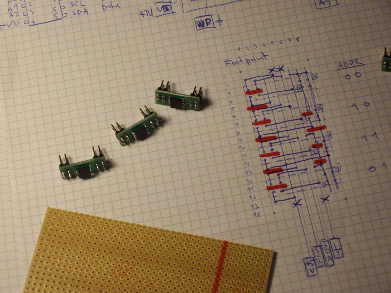
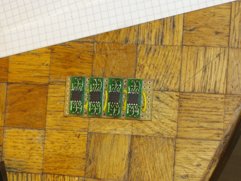
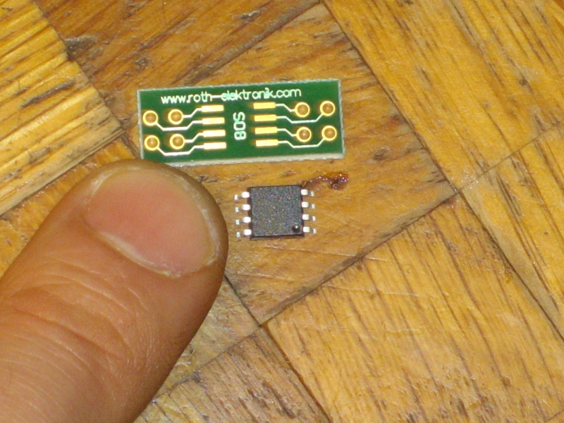
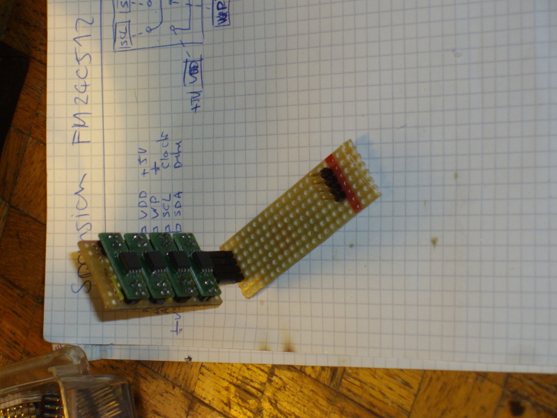
I just received the IC's and built a PCB with 4 of them, I used some "SMD wrappers" to mount the IC's (This rellay costs nerves if you don't have flux on hand, I've got to learn design/etch PCBs!) Next step is to write a driver in ASM for these, this will cost me some more nerves because this is my first ASM project :) Enjoy the pictures
-
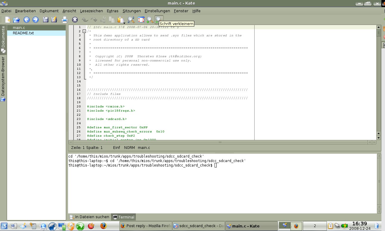
maybe it's a bit late to enter this discussion.. but kate! It comes with kubuntu (KDE 4). Me personally prefer the KDE desktop because of it's rich possibilities to configure (smaller icons etcetcetc.), and the better & more tools. kate is just perfect for MIDIBox, you can have a console window open inside it, the current dir will automatically switch to the file's dir that you are working on. You just type "make" ;) - tabs - code highlighting - open/close code trees I can confirm that ubuntu / kubuntu "just works" out of the box! I installed it on a Toshiba Sattelite laptop. Everything worked without post-installing a single driver! - USBBildschirmphoto2.png - Card reader - Soundcard - HP Laserjet printer - Firewire Audio device with jack/freebob installing additional packages is a peace of cake with the adept package GUI / adept application manager. no need to go to the shell.
-
hello all, based on the SD-card module written by TK, I wrote an application that does some tests on the connected sd-card: 1. find the first writeable sector (the cards I tested this is always 0x00) 2. find the last writeable sector. this depends on how much sectors your card uses for internal stuff. 3. deep check the sectors (write/read/compare) inside the R/W range at the end of the test, you will know: - if your sd-card works, how much sectors failed the r/w/c test - which range you can use to store data with your application maybe this information could be fetched from the card directly, I think there should be some info-record somewhere on the card, that tells you about the type/size of the card. if someone knows about that, please tell me.. I tested the app with a Pretec 256MB card and a SanDisk 1GB. Both works fine. For the deep check, you can re-define "check_step". To check every sector is possible, but takes a very long time (ca. 2 hours for 256MB card). I set "check-step" by default to 0xF2. I noticed that sometimes after a read/write error, the card refuses to communicate further on. After every read/write error, I re-init the card (SDCard_Init()). The application can be found in the repository: "trunk/apps/troubleshooting/sdcc_sdcard_check". More info in the README.txt. on the hardware-side, I used the schematic introduced here: http://www.midibox.org/forum/index.php/topic,11484.msg97787.html#msg97787 Of course it's better to use a voltage-regulator instead of two diodes, but as I couldn't buy one so far, I also used the two diodes. I also tried three, but as the voltage drop is not absolutely constant, it will drop too much when the card is consuming power. Two is just right, I used two fast switching SI types (the small ones in the glass tubes).
-
Unsolved new wiki - pagenames / namespaces
This N°9 replied to This N°9's topic in MIDIbox Documentation Project
overhaul process: I like the idea of stryd, but there's a bigger risk to miss some links, say somebody overhauls a page, and on this one you have links to a page that doesnt exist yet.. one way would be to setup this link to point to the proper place, and leave it uncreated until it's the next candidate in the list. the other approach would be to start from existing pages and follow the links and create the pages that are not created yet. this way the new wiki would "grow" like a tree from bottom up. maybe some kind of "overhaul" wiki-page would also be a variant, like to list all the new pages that are created in a tree manner, and add the sources to it: -home -home:project [overhauled from project] -... just a proposition -
Unsolved new wiki - pagenames / namespaces
This N°9 replied to This N°9's topic in MIDIbox Documentation Project
I think from time to time it's good to setup things in a new way from ground up, taking the old resources and tight them up etc. I need to do this in my citchen sometimes if I didn't clean up for some time :) It just make things more thight and handy for the reader, there is a process of reflecting things once more, filter them and skip information that is not usefull or modifiy it to fit clearer to the rest etc. In my eyes this is the benefit of bulding a new one from ground up, taking the resources of the old one as "source" or "input". -
Unsolved new wiki - pagenames / namespaces
This N°9 replied to This N°9's topic in MIDIbox Documentation Project
I suppose to add some comment like "this page has been overhauled to the new wiki <link>. If you modifiy this page, please also modifiy this comment and write what you changed!" on the top of the page. -
what I wanted to say is that if SD out is 0V, the wire is on ground level, pulling the 5V down to 0V, which results in logic low for the PIC input. That's what I didn't understand before. The concept of the 10K pull-up is clear to me now, and I also see it's advantage. thanks for your explanations, this
-
Yes. I just imagined that the 5V+ connected to the pin could "override" the communication. But if the output pin of the SDcard is grounded when it is low (which seems logic now if I think about it), this will make no difference. The concept of having a high state when nothing is connected is clear to me. no, to be honest, I have to solder the components first :) Ok, it should be in the trouble-avoiding section :) When I started the the thread, it seemed to be the best place to go, maybe it should be in parts questions or design concepts. sorry about that.
-
Thanks for answer & updates.. Concerning the storage issue, I found my dream-device, see this thread: http://www.midibox.org/forum/index.php/topic,12641.0.html I will use this one as "working" storage (for the current song/setup), and use the flash card as backup/restore device for whole songs/setups. If doing so, the 512bytes write/read is no problem. now I think I understand. The "pure" form BRA will only apply if I use a literal, with labels the assembler will calculate the relative offset.
-
hm, I suppose the output of the flash card must be on ground when it is low?
-
I'am building a board with a SD-card slot on it, which should interface with MBHP. I found this schematic: http://www.midibox.org/forum/index.php?action=dlattach;topic=11484.0;attach=3351;image now my questions: - I suppose the data-out of the sdcard is a "active" output, not an open collector? If so, the resistor connecting to +5V from core::J6:SI has to be removed? -does it matter if I take 3,3K/1,8K combination or 22K/10K ?
-
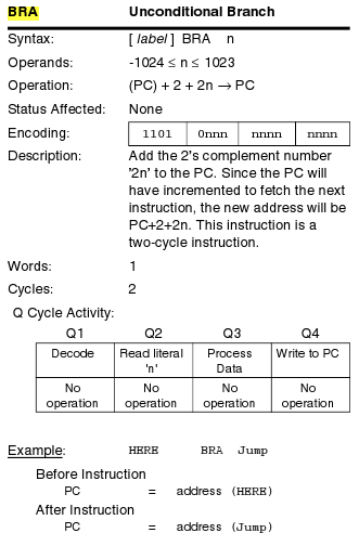
I give it one more try.. : BRA $+2 ;I want to branch to the next instruction assume $ is 0x222222, $ == PC new PC = 0x222222+2+2*0x222222 the result of the above formula will for sure *not* equal to 0x222224 ! ?
-
seems to.. or I missunderstand something: PC+2+2*nd -> PC nd is the param for BRA. The spec says that the above formula will be performed to set the new PC. But it seems that it is also possible to just branch to a absolute address. But the BRA is described as "relative branch". This confuses me.
-
The speed will be sufficient for my needs, and it doesnt matter if I read a single byte or a series of them. So no more buffering needed on reads! I can just test if I need more data, if not, I close the stream. And.. writes will be performed the same speed as reads, no delays, full clock speed! 1MB is enough for one "song", I will use the SDcard to stuff the current song to a bigger storage, the FRAMs will be my working-space. The FRAM technology seems to be quite new, it uses not floating gate transistors, but "cells" that can keep potentials like a condesator, but some kind of piezzo-like cristal material is used.
-
I read the specs of both the bankstick 24LC512 and the Ramton FM24C512 (atention! there are devices with the same type name that are EEProm devices, not ferroelectric!). I must say I'm absolutely excited! This is THE thing! The only negative aspects may be the fact that it is only available as SMD, and that there are only 2 device address pins. But this is exactly what I need for the sequencer I plan, I can read and write randomly from it at both full speed without any delays, and it's very enduring. Life extending stuff could be done, but is absolutly not necessary. This is a quote from the spec: "Even at 30 accesses per second to the same segment, 10 years time will pass before 10 billion endurance cycles occur". I suppose until then we will have some holographic storage or something.. :D The protocoll is different from the 24LC512, but very handy. It's also based on IIC, max. clock frequency is 1MHz. I'll order some FM24C512 from onlinecomponents.com (they ship internationally), and write a driver for it. Hardware interface is the same as for the banksticks, they could even be mixed in the same chain, using either the regular bankstick functions or the FRAM driver functions. Subsequent reads/writes are possible and don't differ from single reads, so I will build stuff to have most flexibility. I will also add a multiplex feature, which can be used with a dual 4-channel analog multiplexer like the 74HC4052. The pins used to multiplex will be configurable, default will be RC4 / RC5. So 4 chains can be used in parallel, which gives you 1MByte FRAM storage. The SDcard driver can be used in parallel with default Port C.
-
yes, I'am aware of that, but the PIC spec (PIC18FXX2->Enhanced 16-Bit Core Instruction Set (75 instruction set)) gives the following definition of the BRA instruction (see screenshot): This is from another spec version: Mnemonic: BRA nd Description: Unconditional relative branch Function : PC+2+2*nd -> PC It's a bit confusing, I suppose the PC+2+2*nd will only apply if n is < 1024.
-
Looking for some kind of serial accessible RAM, I found someting interesting. It's a non-volatile RAM device (Ferroelectric technology). features: - up to 512Kbits (4, 64, 256 also available) storage - no delays on writes (!) - up to 1MHz clock frequency - two-wire serial communication (SC / SD) - two address pins (up to 4 devices) - 10 billion (10^10) write/read cycle life endurance (!) It's a bit more expensive than a bankstick with the same size (ca. 15$ / 10eur for a 256Kb @ farnell), and seems to be harder to get. For the 512Kb I only found the datasheets so far, and the 256Kb I only found @ farnell. Maybe somebody knows more about it, or even has experiences with this device type. I will study it a bit more, and check for other sources. I attached the datasheet for everbody who likes to know more. EDIT: also available here (USA), much cheaper than in europe: http://www.futureelectronics.com/en/technologies/semiconductors/memory/fram-mram/Pages/8772774-FM24C512-G.aspx?CrossPart= even cheaper (bulk order): http://www.onlinecomponents.com/buy/RAMTRON/FM24C512-G/ fm24c512_datasheet.pdf fm24c512_datasheet.pdf
-
just to continue the story: I studied a lot of specs and asm code (sd card module, spansion spec, sd card spec ..), here some hints & questions: the spansion IC's are not made for this kind of usage, 1st they have no kind of controller mechanism for erease/write/sector assign etcetc. even doing this on software side is hardly possible, because one sector is 256Kbits, and has to be ereased before re-programming. The IC's could only be usefull for bigger data ammount backup/restore. But the protocoll is very flexible, so byte-read will automatically increase the address pointer to the next byte, as long a clock is received, the IC will output bytes. Anyway it's not usefull for my seq project. The problem with the SDcard again is, that only some cards seem to support block reads of less than 512bytes. The problem is that this is quite a lot of data for the poor PIC, and if I ignore some of it, it will be just wasted CPU time. 3mS*16 (worst case read time for 16 streams) is really a lot of time. Maybe I'll just use a bankstick array of 32 sticks (->2MBytes) and use the SDcard as backup device to share with the PC. The read/write on the BS is fast enough, and 64 bytes is still ok if I send some bytes immediately and buffer some more, so redundant read access will be not so dramatically high. @TK I studied your SD-card asm code (and learned some asm by the way..), now I'm a bit confused about the usage of the unit "mS": in the code you have a helper macro called "SDCARD_1mS_Delay". I assume that here it means "micro" not "milli" (?) The second thing that makes my brain smoke is the line "bra $ + 2". I understand that the idea is to perform 2 cycles and go to the next command, but in the PIC18F452 datasheet I see this definition for the "BRA" command: BRA nd ; PC+2+2*nd->PC" If this is the correct reference I'm reading, "bra $+2" would branch to $+2+($+2)*2 rather than to the next instruction, or will the use of $ cause some special handling by the assembler? thanks for your inputs
-
ok, release is in the wiki, documentation finished, usage manual (.pdf) added 8)
-
Thats what I wanted to know. For me this is no problem, I could upload it myself. I just see that other dists are located on the ucapps-site so I didn't know what's the idea for finished releases. I will upload it to the wiki-filespace, there I can also update it myself, If there should be any bugfixes or so (hopefully not) :-)
-
forget about the scope. I have one, but an analog one, I only needed it to debug analog circuits like tape machines etc. , for digital circuits it's useless. Maybe I can see if there is something switching or not, but to track what excatly is happening, you would need a digital scope or a extension device/board to connect to the PC, where you could record the action. and then, you would need the knowledge about the protocoll going on etcetc. keep it simple, just build a simple MIDI-Box with a core and some DIN's / DOUT's or so and check the stuff out. I promise you will not need a scope for that.
-
You will never have to check digital signal flow with MIDIbox components. If something does not work, you mostly have bad solder spots, forgot to solder something, or you have solder bridges (shortcuts) somewhere, or you put polarized components the wrong way roung.. these things you can check by eye or with a multimeter checking the if the paths are correct.