

Gridracer
-
Posts
142 -
Joined
-
Last visited
-
Days Won
1
Content Type
Profiles
Forums
Blogs
Gallery
Posts posted by Gridracer
-
-
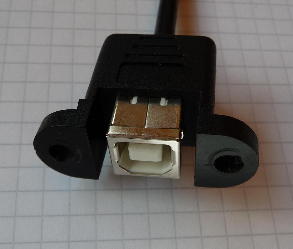
After a long search for a cheap panelmount USB socket (2,49€)
I found this one to use it in my midibox.
(Also available in type A)
Might be useful for others.
Best Regards
Gridracer
-
You have to "fire" the song position by using one of the 16 GP buttons.
Each GP button selects another song position (accordingly 16 "phrases" can be selected).
Ah, now it is clear, i was missing "Each GP button selects another song position" as the manual says
"By pushing a GP button, the sequencer will execute the action defined at song position A1, B1, C1..P1"
Now that I know i think it is quiet easy and comfortable.
Anyway I just wasn't trying hard enough in advance.
Best Regards
Gridracer
-
I'm planning to improve the CC number entry in Event Track and LFO Configuration page this way: selection of CC with rotary encoder, confirmation with GP button, so that CC doesn't change immediately (resp. "random CCs" will be sent while a sequence is playing)
Funny, just two hours ago I managed to completely confuse one of my synths by scrolling through the CCs so that only powering off and on could bring it back to life.
How about this:
Couldn't you display a message in Event Track page when changing the CCs like:
"Confirm with SELECT" like in a way when saving a pattern on SEQV3?
But I think it is not a big issue as you can mute the parameter layer in advance.
And in the LFO Configuration page you can set the LFO to off for CCs while selecting.
But non the less, the 3s waiting time wolud be an additional help.
EDIT:
Another Idea:
How about to mark parameters that should not be automatically updated by turning the encoder
with e.g. a "!" sign ahead of their name to indicate that their change has to be confirmed by pressing the
GP Button below. I think that would be easy to learn and keep in mind if it would be possible to keep
that consistant within all menu pages.
Best Regards
Gridracer
-
Btw. Gridracer: please let me know when you are ready to test a modified firmware for debugging the chaselight issue you reported (I already wrote you a PM, but haven't got an answer).
Dearful sorry, I did not notice the PM.
But now I uploaded the new file and everything works perfect!!
Thank you very much!
Best regards
Gridracer
-
TROUBLE WITH PHRASE MODE
Hi, I am not sure if I am doing something wrong, but I can not get my SEQ (Beta6) to
execute the action defined at song position when I am in phrase mode.
I use encoder #2 to change the song position but the new position will only flash in the
display and nothing will happen.
Am I missing something? Do I have to do something to execute the action defined at the
new song position?
Best regards
Gridracer
-
I checked track length 64 at my box, here etherything OK, 64 steps playing with divider 16 or 16T.
I also checked other track lengths.
But I have an Issue with the chaselight on the LED MATRIX when the length of one Track is longer than16:
When the selected Track is the one with more than 16 steps the chaselights of the other three Tracks
freeze when the Chaselight of the selected (> 16steps) Track reaches step 17, and they stay frozen untill the chaselight of the selected (> 16steps) Track reaches step 1 again.
When the selected Track is one with Steplength < or = 16 everything is OK.
This is reproduceable.
EDIT:
here is a link to a videoclip showing this Bug:
http://www.flickr.com/photos/gridracer/4011133399/
(Track 1=Length8, Track 2=Length32, Track 3&4=Length16)
Best Regards Gridracer
-
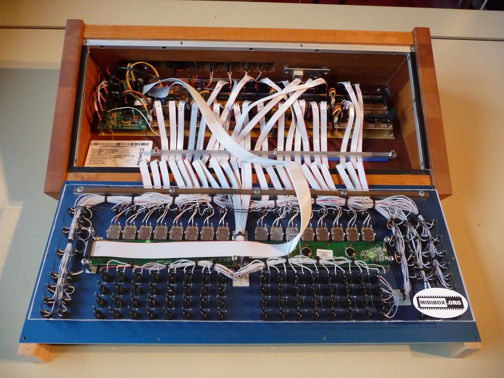
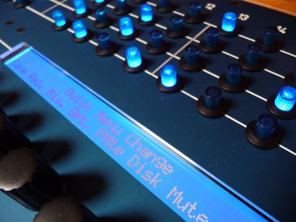
Now after some enjoyable months with SEQV3 here are some new pics from updating to V4 this week:
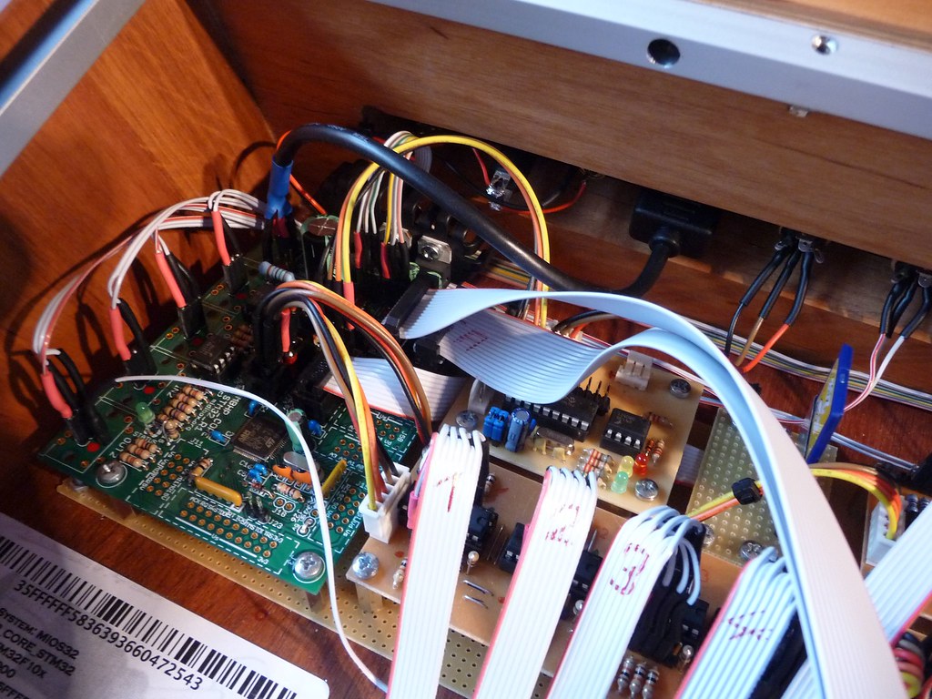
By the way, shortly after I had finished my SEQV3 I changed the resistors of the LEDs as I noticed
that they were much too bright:
I now use:
8,2KOhm !! for the blue non multiplexed LEDs
1,3KOhm for the blue multiplexed matrix LEDs
470Ohm for all red LEDs
(for all green and yellow LEDs i kept 220Ohm)
Now all LEDs look equal bright and are gentle to the eye, esspecially the blue ones do not spike out any more, which is clearly visible if you compare this new picture with my older pictures
on the beginning of this thread
some more pics:
http://www.flickr.com/photos/gridracer/sets/72157613814527297/
-
I never used an EXIT LED by myself... Wink
I wouldn't either but all of my Buttons have an LED by default....
so why not use them... and I really like the buttons to glow... ;)
Next bug, please.-Well, now the EXIT LED does not work at all
EDIT: removed entry about EDIT LED (user error)
Finally,
i would like to ask for a TRANSPOSE LED in some future release. Shame on me!
It is the only LED one not in us on my entire Frontpanel ... so just for the bling...
->super super low priority
Best regards Gridracer
-
EXIT LED BUG
just toyed around with V4Beta3 and noticed that there is a little bug with the Exit LED:
EXIT LED will not go on when the EXIT button is pressed, but depressing the EDIT button will cause it to
light. (EDIT LED works right, EDIT and EXIT button call the right menu page)
I think I can exclude a hardware issue as it does not matter to what shift register nr. and pin nr. I connect the EXIT LED and assign it in the setup file, the effect stays the same.
Best Regards
Gridracer
-
SOLVED: BLM MATRIX PROBLEMS on SEQ V4
just uploaded Beta 3 and now the matrix works fine!
Thanks TK!
Best Regards
Gridracer
-
BLM MATRIX PROBLEMS on SEQ V4:
Just finished updating my SEQ to V4.
Everything works perfect except one thinng:
The LEDs on my BLM seem to be wrong adressed.
On an empty pattern all LEDs on the four tracks are off. Ok so far.
But when I set one step, the LEDs of the the wrong Track is set or the other tracks are inverted.
(e.g. i set step 9 on track 2 -> step 9 on tracks 1,3,4 LED on track 2 stay off)
(or if i set a step on Track 3 the LED on Track 1 will be inverted)
(lots of more strange effects on the BLM LEDs...)
The chaselight works partly correct on all four Tracks, with the exception that on active steps
the LED does not go off but stays on.
The Buttons on the matrix work 100% right!
(same effect if I use matrix or GP buttons to set steps)
(the BLM worked right with SEQ V3, no hardware changes during update to V4)
I use sinkdrivers for the Cathodes, but it makes no difference whether I set the Inversion Mask 0x00 or 0xf0.
Behaviour of the LEDs is the same with both settings!
(I know that my configfile is loaded as all customized button/LED assignments work)
So my question: Is the BLM not fully supported yet?
Or any suggestions what could be wrong?
Best regards
Gridracer
EDIT: specified error description
here my MBSEQ_HW settings:
##################################################
# Setup File for Chainreactor Frontpanel
# $Id: MBSEQ_HW.V4 630 2009-06-28 20:24:53Z tk $
##################################################


##################################################
# Shift Register Setup
##################################################

# number of first and second DOUT shift register used for GP LEDs
GP_DOUT_L_SR    3
GP_DOUT_R_SR    4

# DOUTs for Dual Color option:
GP_DOUT_L2_SR  0
GP_DOUT_R2_SR  0


##################################################
# Optional BLM Matrix
##################################################

# set this value to 1 if each track has its own set of 16 LEDs to display unmuted steps and current sequencer position
# or if you are using a button/led matrix for misc. button/LED functions
BLM_ENABLED     1

# define the shift registers to which the anodes of these LEDs are connected
# Note: they can be equal to GP_DOUT_[LH]_SR, this saves two shift registers, but doesn't allow a separate view of UI selections
BLM_DOUT_L1_SR	6
BLM_DOUT_R1_SR	7

# define the shift register to which the cathodes of these LEDs are connected
# Note that the whole shift register (8 pins) will be allocated! The 4 select lines are duplicated (4 for LED matrix, 4 for button matrix)
# The second DOUT_CATHODES2 selection is optional if LEDs with high power consumption are used - set this to 0 if not used
BLM_DOUT_CATHODES_SR1  5
BLM_DOUT_CATHODES_SR2  0

# set an inversion mask for the DOUT shift registers if sink drivers (transistors)
# have been added to the cathode lines
# Settings: 0x00 - no sink drivers
#           0xf0 - sink drivers connected to D0..D3
#           0x0f - sink drivers connected to D7..D4
BLM_DOUT_CATHODES_INV_MASK 0xf0

# 0: no DUO colour LEDs are connected to the LED matrix (position marker inverts step LED)
# 1: DUO colour LEDs are connected to the LED matrix, second LED displays position marker
# 2: Like option 1, but the first LED is turned off when the position marker activates the second LED
BLM_DOUT_DUOCOLOUR  0

# define the shift registers to which the anodes of the "second colour" (red) LEDs are connected
BLM_DOUT_L2_SR  0
BLM_DOUT_R2_SR  0

# set this to 1 if a button matrix is connected
BLM_BUTTONS_ENABLED 1

# set this to 1 if these buttons should only control the "step triggers" (gate, and other assigned triggers) - and no UI functions
BLM_BUTTONS_NO_UI   1

# define the DIN shift registers to which the button matrix is connected
BLM_DIN_L_SR  6
BLM_DIN_R_SR  7


##################################################
# Additional 8x8 BLM as used for Wilba's Frontpannel
##################################################

# set to 1 to enable 8x8 BLM driver
BLM8X8_ENABLED  0

# to which shift register are the select lines connected?
# Allowed values: 0 to disable, 1..16 to assign shift register
BLM8X8_DOUT_CATHODES_SR  0

# set an inversion mask for the DOUT shift registers if sink drivers (transistors)
# have been added to the cathode lines
BLM8X8_DOUT_CATHODES_INV_MASK 0x00

# to which shift register are the LED anode lines connected?
# Allowed values: 0 to disable, 1..16 to assign shift register
BLM8X8_DOUT_LED_SR	0

# 0: no mapping of 8x8 LEDs
# 1: enable GP LED -> 8x8 matrix mapping for Wilba's MB-SEQ PCB
BLM8X8_DOUT_GP_MAPPING  0

# 8x8 matrix for misc. button functions
BLM8X8_DIN_SR  0


##################################################
# CV and Gate/Trigger/Sync Setup
##################################################

# define the AOUT interface which is connected to the core
#  1: a MBHP_AOUT module
#  2: up to 4 (chained) MBHP_AOUT_LC modules in 8/8 bit configuration
#  3: a MBHP_AOUT_NG module
AOUT_INTERFACE_TYPE 1

# additional gate triggers are available on common digital output pins of the
# DOUT shift register chain - they are assigned to AOUT channel #16 (Note C-1, C#1, D-1, ...)
# define the shift registers which should be used here (each provides 8 gates)
# Note that SRs assigned to this function cannot be used as LED outputs (exclusive function)
# Allowed values: 1-16, 0 disables the function, all other values invalid and not allowed
DOUT_GATE_SR1   0
DOUT_GATE_SR2   0
DOUT_GATE_SR3   0
DOUT_GATE_SR4   0
DOUT_GATE_SR5   0
DOUT_GATE_SR6   0
DOUT_GATE_SR7   0
DOUT_GATE_SR8   0

# if set to 1, the DOUT "gates" will send 1mS pulses
# useful for analog drums
DOUT_1MS_TRIGGER 0

# should J5A/B/C outputs be enabled (0: no, 1: yes, 2: yes, but in open drain mode)?
#  - the 8 AOUT gates will be forwarded to J5A/B
#  - DIN sync clock will be forwarded to J5C:A0
#  - DIN sync start/stop will be forwarded to J5C:A1
#  - if open drain mode enabled (option 2), external pull-ups have to be connected to J5 pins
#    (advantage: pin levels can be pulled to 5V)
#
# NEVER USE THIS TOGETHER WITH ANALOG POTS - IT WILL CAUSE A SHORT CIRCUIT!
J5_ENABLED 0


##################################################
# LED assignments to DOUT pins
# SR = 0: LED disabled
# SR = 1..16:  directly forwarded to DOUT pin
# SR = 17..24: forwarded to a 8x8 LED matrix
##################################################

#           SR  Pin
LED_TRACK1   1   0
LED_TRACK2   1   1
LED_TRACK3   1   2
LED_TRACK4   1   3

#                SR  Pin
LED_PAR_LAYER_A   1   4
LED_PAR_LAYER_B   1   5
LED_PAR_LAYER_C   1   6

#         SR  Pin
LED_BEAT   1   7

#           SR  Pin
LED_EDIT     2   0
LED_MUTE     2   1
LED_PATTERN  2   2
LED_SONG     2   3

#           SR  Pin
LED_SOLO     2   4
LED_FAST     2   5
LED_ALL      2   6

#           SR  Pin
LED_GROUP1  8   0
LED_GROUP2  8   1
LED_GROUP3  8   2
LED_GROUP4  8   3

#                SR  Pin
LED_TRG_LAYER_A   9   0
LED_TRG_LAYER_B   9   1
LED_TRG_LAYER_C   9   2

#           SR  Pin
LED_PLAY     9   3
LED_STOP     9   4
LED_PAUSE    9   5
LED_REW     10   3
LED_FWD     10   4
LED_LOOP     0   0

#               SR  Pin
LED_EXIT        10   5
LED_SELECT      10   6
LED_MENU        10   7
LED_SCRUB       10   2
LED_METRONOME    0   0
LED_RECORD       8   4
LED_UTILITY      8   7
LED_COPY         8   6
LED_PASTE        8   5
LED_CLEAR        0   0

#                  SR  Pin
LED_STEP_VIEW       9   7
LED_PAR_LAYER_SEL   0   0
LED_TRG_LAYER_SEL   0   0
LED_TRACK_SEL       9   6

#                  SR  Pin
LED_TAP_TEMPO       0   0
LED_TEMPO_PRESET    0   0
LED_EXT_RESTART     0   0

#         SR  Pin
LED_DOWN   0   0
LED_UP     0   0


##################################################
# Button assignments to DIN pins
# SR = 0: Button disabled
# SR = 1..16:  directly triggered from DIN pin
# SR = 17..24: triggered from a 8x8 button matrix
##################################################

#            SR  Pin
BUTTON_DOWN   1   0
BUTTON_UP     1   1
BUTTON_LEFT   0   0
BUTTON_RIGHT  0   0

#                 SR  Pin
BUTTON_SCRUB       1   7
BUTTON_METRONOME   0   0
BUTTON_RECORD     13   1

#             SR  Pin
BUTTON_STOP    11   2
BUTTON_PAUSE   12   1
BUTTON_PLAY    12   7
BUTTON_REW     11   7
BUTTON_FWD     13   6
BUTTON_LOOP    0   0

#              SR  Pin
BUTTON_MENU     11   0
BUTTON_SELECT   12   0
BUTTON_EXIT     13   0

#              SR  Pin
BUTTON_TRACK1   2   3
BUTTON_TRACK2   2   5
BUTTON_TRACK3   2   2
BUTTON_TRACK4   2   6

#                   SR  Pin
BUTTON_PAR_LAYER_A  11   4
BUTTON_PAR_LAYER_B  11   3
BUTTON_PAR_LAYER_C  11   5

#                SR  Pin
BUTTON_EDIT      11   6
BUTTON_MUTE       2   0
BUTTON_PATTERN   12   3
BUTTON_SONG      12   4

#            SR  Pin
BUTTON_SOLO   2   7
BUTTON_FAST   1   6
BUTTON_ALL    2   1

#            SR  Pin
BUTTON_GP1    3   0
BUTTON_GP2    3   1
BUTTON_GP3    3   2
BUTTON_GP4    3   3
BUTTON_GP5    3   4
BUTTON_GP6    3   5
BUTTON_GP7    3   6
BUTTON_GP8    3   7
BUTTON_GP9    8   0
BUTTON_GP10   8   1
BUTTON_GP11   8   2
BUTTON_GP12   8   3
BUTTON_GP13   8   4
BUTTON_GP14   8   5
BUTTON_GP15   8   6
BUTTON_GP16   8   7

#              SR  Pin
BUTTON_GROUP1  2   4
BUTTON_GROUP2  1   4
BUTTON_GROUP3  1   3
BUTTON_GROUP4  1   5

#                   SR  Pin
BUTTON_TRG_LAYER_A  12   5
BUTTON_TRG_LAYER_B  12   2
BUTTON_TRG_LAYER_C  12   6


# Following button functions are usually assigned to Fx
# buttons, or to dedicated (labeled) buttons
# In the standard frontpanel layout:
# F1 is located at SR 13 Pin 4
# F2 is located at SR 13 Pin 2
# F3 is located at SR 13 Pin 5
# F4 is located at SR 13 Pin 1

#                    SR  Pin
BUTTON_UTILITY       13   4
BUTTON_STEP_VIEW     11   1
BUTTON_TRG_LAYER_SEL  0   0
BUTTON_TRACK_SEL     13   7

BUTTON_PAR_LAYER_SEL  0   0

#                    SR  Pin
BUTTON_TAP_TEMPO     13   3
BUTTON_TEMPO_PRESET   0   0
BUTTON_EXT_RESTART    0   0

#                SR  Pin
BUTTON_COPY      13   2
BUTTON_PASTE     13   5
BUTTON_CLEAR      0   0


#                SR  Pin
BUTTON_MORPH      0   0
BUTTON_MIXER      0   0
BUTTON_TRANSPOSE  1   2


##################################################
# Button behaviour
# 0: active mode so long button pressed
# 1: pressing button toggles the mode
##################################################

BUTTON_BEH_FAST         1
BUTTON_BEH_ALL          1
BUTTON_BEH_SOLO         1
BUTTON_BEH_METRONOME    1
BUTTON_BEH_LOOP         1
BUTTON_BEH_SCRUB        0
BUTTON_BEH_MENU         1
BUTTON_BEH_STEP_VIEW    1
BUTTON_BEH_TRG_LAYER    1
BUTTON_BEH_PAR_LAYER    1
BUTTON_BEH_TRACK_SEL    0
BUTTON_BEH_TEMPO_PRESET 0


##################################################
# Special Behaviour of ALL button
# 0: only all parameter layers are modified
# 1: all trigger and parameter layers are modified
##################################################
BUTTON_BEH_ALL_WITH_TRIGGERS 0


##################################################
# Encoder Functions
# SR = 0: encoder disabled
# SR = 1..16: DIN assignment
# Types: NON_DETENTED, DETENTED1, DETENTED2, DETENTED3
##################################################

#              SR  Pin  Type
ENC_DATAWHEEL   1   0   DETENTED2

# the speed value for the datawheel which is used when the "FAST" button is activated:
ENC_DATAWHEEL_FAST_SPEED 3

#         SR  Pin  Type
ENC_GP1    4   0   DETENTED2
ENC_GP2    4   2   DETENTED2
ENC_GP3    4   4   DETENTED2
ENC_GP4    4   6   DETENTED2
ENC_GP5    5   0   DETENTED2
ENC_GP6    5   2   DETENTED2
ENC_GP7    5   4   DETENTED2
ENC_GP8    5   6   DETENTED2
ENC_GP9    9   0   DETENTED2
ENC_GP10   9   2   DETENTED2
ENC_GP11   9   4   DETENTED2
ENC_GP12   9   6   DETENTED2
ENC_GP13  10   0   DETENTED2
ENC_GP14  10   2   DETENTED2
ENC_GP15  10   4   DETENTED2
ENC_GP16  10   6   DETENTED2

# the speed value for GP encoders which is used when the "FAST" button is activated:
ENC_GP_FAST_SPEED 3

# Auto FAST mode: if a layer is assigned to velocity or CC, the fast button will be automatically
# enabled - in other cases (e.g. Note or Length), the fast button will be automatically disabled
ENC_AUTO_FAST        1
-
Time to heat up the soldering iron again...
What better to do on some upcoming rainy autumn evening than updating to V4!
Thank you a lot for all the effort TK, and everyone else envolved.
I am still so amazed by my SEQV3 what an incredible machine!
Best regards Gridracer
-
I had this behaviour on all of my encoders on my SEQ:
I used ALPS encoder STEC16B04 743420 from www.distrelec.de
But they only decreased values when I connected them as described in the wiki.
I got them to work by switching ground and highest din pin.
That only one of your encoders goes mad seams weird.
But you migth check all combinations to connect it's three pins an see if you can get it work.
Finally that is what I did. Good thing is that you can't break anything by doing so.
Hope you have success.
Gridracer.
-
Congrats!!
very cool looking box in nice desktop case!
Thougth about adding self adhesive foil with printed label (and perhaps graphics) to make it perfect?
Greetings Gridracer
-
Hello TK, a tiny wish from my side:
Could you please add, anytime, just before the official release,
the definition of a record button
to the MBSEQ_HW file to call the record page ?
On my SEQ V3 i assigned the record page to one of the F-buttons
as I like to have quick access to it when fooling around with a keyeboard.
Thanks a lot and best regards
gridracer
-
Words fail me...
Great Music and a phantastic instrument!
Really like the echo FX, loved it on my RS700.. now MIDbox SEQ can also do it :)
(and shurely much better)
Greetings
Gridracer
-
Just found while surfing around:


Did not try it myself, but perhaps will when it is time to update to MB SEQ V4
-
Thank you both,
now that I know what to focus on, the difference is obvious.
-
I just fail to figure out the difference between the direction parameters
PENDULUM and PING-PONG ??
Perhaps somebody could explain it to my dumb self.
Best regards, Gridracer
-
I like the inversion behaviour of the ALL button very much, as I can quickly set up a new track:
1- I start with an empty track
2- Push the all button
3- push any GP button -> all steps get set
4- I use the data wheel to find the right base note, chord, or druminstrument
5- I push again any GP button -> all steps get swiched off
6- Push the all button again
-> Now i built the melodic or rythmic structure by swiching on certain steps and increasing or decreasing
values with the encoders
Best regards Gridracer
-
[quote name=TK on: 2009-05-19 at 20:38
]I just have added BUTTON_MORPH, BUTTON_MIXER and BUTTON_TRANSPOSE
-
....................which they would do with an delay of at least six months..........commercial companies would already release it as a v4.0 version.which tells us again that commercial products just can't meet midibox standards.... :)
all hardware settings are done in a configuration file stored on SD card (see MBSEQ_HW.V4)That's nice! But from looking at that file I could not figure out if it will be possible to assign menu functions to the F1-F4 buttons like on MB SEQ3.4 by editing SEQ_BUTTONS.INC:
e.g. I use the F2,3,4 buttons to call MORPH, MIXER, TRANSPOSE Page as I use them frequently.
How would this look like in MBSEQ_HW, or is it no longer possible?
greetings, Gridracer
-
Just a suggestion, as your upload troubles and test results remind me of the problems I had with my core:
It could be a faulty optocoupler? One of those beasts messed up the midi in on my box although it passed all tests.
Wish you much success!
-
I would think about getting one or two 6N138 Optocouplers as spares
(required for the midi in on core ande IIC Midi module)
they cost abou1€ and they are a common source of trouble
Just search the forum.
J was really regretting not having ordered them as spares during my SEQ project...
Be sure to order the right PIC: 18F4620
If you order at MIKE's shop do not overlook the 8xBankstick PCB
I wish you much success!
Sorry to ask but i need donations
in Latest News
Posted
So did I.....
But 2010 is there soon, so I am sure $ will come to good use ;)