MONSTA
-
Posts
87 -
Joined
-
Last visited
Content Type
Profiles
Forums
Blogs
Gallery
Everything posted by MONSTA
-
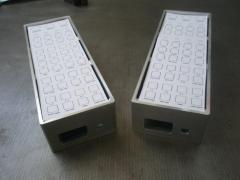
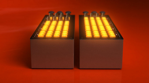
From the album: Monsta
Just got these pictures back from my cousin who's making up the cases for me! They're going to be powder coated black and have a Satin black perspex faceplate. The holes at the back are for a USB port and an IEC port (kettle lead). Lets hope it all fits together nicley eh! -
Thanks Thorsten, I'll check that out tonight. Monsta
-
Hey everyone. I have a fully working Core with GM5, but I'd like to swap the GM5 to EEPROM mode so I can name the Midi Device and change it's I/Os to 1 (I know I can do this physically, but I'm going to be using two GM5's so want them named properly as well). I've installed GPUTILS and SDCC which both seem to be installed properly, but when I download the SVN of mbhp_usb_gm5_eeprom and try to run "make" in terminal, I get this error: Makefile:28: /include/makefile/common.mk: No such file or directory Makefile:31: /modules/app_lcd/dummy/app_lcd.mk: No such file or directory Makefile:34: /modules/iic_eeprom8/iic_eeprom8.mk: No such file or directory make: *** No rule to make target `/modules/iic_eeprom8/iic_eeprom8.mk'. Stop. Is the SVN thats up correct, or is my install borked? Thanks for any help Peeps Monsta
-
Ok, thanks guys, I hadn't really anticipated this. I guess I looked at the akai thing and read a few half related posts on here and jumped to conclusions. So I can test with a wallwart I have now, which i have used for testing a different core in the past. But idealy I'd just want to have an iec/kettle plug port on the back that'll connect straight into a psu then into the j1 etc. Can I build one up based on that c64 optimised schematic I've seen around?
-
Hey guys, Nils, no I don't know what I'm doing :) I've managed to wing most of my electronics projects, but I'm not a circuits genius by any means! I can't believe you can't power everything off the gm5! I did my research and people were saying that as long as you weren't using LCD's etc it would be fine. Take a look at the attached image to see what I'm building, there is a CORE, 2xDOUT, 2xDIN and 1xAIN in each one + the GM5. I guess it's not really a massive issue having to use an external power source (there's no room to build one inside), but is this definate that what I'm trying to do with the GM5 is completly misguided and not going to work? Thanks Monsta

-
Hey everyone, I bought an entire Midibox64 kit from smashTV, built it up and tried testing the voltage of the core with a GM5 supplying the power and I'm only getting 1.4v (the GM5 is ouputting about 5v). With my first kit from Mikes Midi Shop I had exactly the same problem, but could get around this by going straight from the GM5 to J2 on the core. The SmashTV core however doesn't have the J2 pins, anyone have any idea how I can get this all connected up? Thanks for any help. Monsta
-
I hated asking for help! I've ordered a new set, so hopefully shout be able to trouble this one better later. I can currently upload hex to it and the LCD responds, but with uploading the 128 app I get this on the LCD: $$6_G$et$$$g=$$$ oN|5$ NICE! I'll see what happens when I get the new kit from SmashTV. But if theres any suggestion on this I'll try it. Thanks MONSTA
-
Thanks man I'll have another go. The LCD displays nothing anymore, which is why I'd given up :P I'l upload midibox64 back to it tonight and see if I have any better look.
-
I am upset at myself for having to ask this, but I've hit a dead end with my MidiBox. I've had the Pic Core up and running and a DIN sending out messages, although to many of them! Now I can't seem to get it to respond, although I can upload hex to it etc... If there's anyone in London or even the UK that would be a kind enough soul to give me a hand on this, I'll be forever greatful! I know its a pain in the arse thing to ask, but I just don't want to waste money on this and am thinking of just buying a new kit from SmashTV (mine is from MikesMIDIshop). Thanks for your time. Christian
-
MIDIbox64 configuration (UPDATE - In DIRE Need of Help!)
MONSTA replied to MONSTA's topic in Testing/Troubleshooting
Anyone? I'm going to have time to mess with this today or tomorrow... Otherwise I'll buy a new core at the end of the month. Christian -
MIDIbox64 configuration (UPDATE - In DIRE Need of Help!)
MONSTA replied to MONSTA's topic in Testing/Troubleshooting
Arghh! I double checked everything today before getting back to you properly. I did mean DINX, sorry about that ;) Ok so connecting QH to ground (and also releasing) writes midi messages to MIOSStudio IN Monitor. If I leave it like that with IC1 out and connect say R9 to VS on J5 nothing happens in the In Monitor... This is really doing my head in now, I just want to get to a stage where I can trigger some midi events properly :P I will be buying a new core at some point for the second controller, but would really like to problem solve this one instead of chucking it. The other Dinx I made also has the same problem! I think it's wired up properly, but maybe I messed up the pull up resistors which are hard to 100% check in the images. Any ideas anyone? I'm about to cry! Niietzshe -
MIDIbox64 configuration (UPDATE - In DIRE Need of Help!)
MONSTA replied to MONSTA's topic in Testing/Troubleshooting
Hey TK, thanks for the info. I uploaded MIOS128 and tested without IC1 in. VS returned something (attached) but VD didn't. I also made up a new AINX and have the same results... I'm presuming this is to do wit my core now AINX01.txt -
MIDIbox64 configuration (UPDATE - In DIRE Need of Help!)
MONSTA replied to MONSTA's topic in Testing/Troubleshooting
Ok I had a chance today to test it and this is the output I get if I just short one of the DIN pins to ground (It will just constantly cycle if I keep it shorted). 00000000023283 ms | [97 54 7F] Channel 8: Note On C6 velocity: 127 00000000023325 ms | [97 54 00] Channel 8: Note On C6 velocity: 0 00000000023349 ms | [97 54 7F] Channel 8: Note On C6 velocity: 127 00000000023382 ms | [97 54 00] Channel 8: Note On C6 velocity: 0 00000000023414 ms | [97 54 7F] Channel 8: Note On C6 velocity: 127 00000000023446 ms | [97 54 00] Channel 8: Note On C6 velocity: 0 Anyone have an idea whats going on with this? Thanks Christian -
 Thats just F***ing epic!
 -
MIDIbox64 configuration (UPDATE - In DIRE Need of Help!)
MONSTA replied to MONSTA's topic in Testing/Troubleshooting
Thanks nILs I'll check it out tomorrow, but my initial thoughts are that shorting it does the same thing as I tried that originally and I believe it was the same behaviour. The buttons I'm using are just shorting the connection as theres no mechanical elements, it just connect ths vs to the vd etc. I'll let you know more tomorrow, but I think this is correct. Thanks for getting back to me Christian -
MIDIbox64 configuration (UPDATE - In DIRE Need of Help!)
MONSTA replied to MONSTA's topic in Testing/Troubleshooting
Am I being stupid or is this normal? Should it only give out one message when it connects? I'm a little stuck what to do now :cry: -
MIDIbox64 configuration (UPDATE - In DIRE Need of Help!)
MONSTA replied to MONSTA's topic in Testing/Troubleshooting
Ok i've scanned every single post in this category to no avail! Does anyone know if this is just a configuration problem or possibly a hardware problem? I wouldn't imagine it to be hardware as I've checked all the joints/tracks and the buttons are responding, just sending too many messages. Here's the diagram of my button pad that I'm using. Ground is the two lines in the middle, each row is connected to a single sil header. Thanks for any help Christian
-
MIDIbox64 configuration (UPDATE - In DIRE Need of Help!)
MONSTA replied to MONSTA's topic in Testing/Troubleshooting
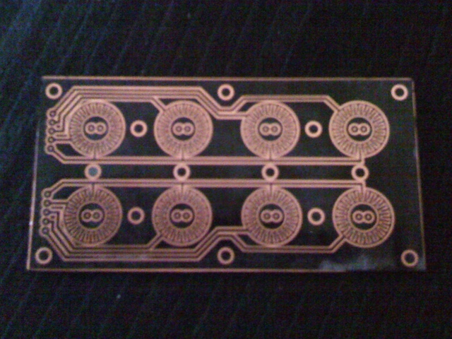
Thanks TK, as always! I'd searched everywhere and never saw that page... I finished up a custom PCB tonight based on the sparkfun button pad boards with just one row of 4 buttons and tested it. If I plug it into J5, J6 or J7 etc they work fine (as long as I haven't pressed the first button before-hand), so I can just skip J3 with the Bank menu as I only need 40 buttons in total. The only thing left is that when I press and hold the button down, it just keeps sending the MIDI message over and over again, which is not what I need. I want to press it down and it sends the message only once until I let go and press it again. There's a bit in the asm that says quality of button, I think it's set to 32 with 0 being high quality. Would you consider this type of button high quality and is it anything to do with why it's sending so many messages? I'm searching the forums for an answer to this, but haven't found it yet. Starting to see the end of the tunnel, but I'm sure it'll throw a few things in my face before I get out the other end. Thanks for all the help again again... Christian P.s. Attached is the board before etching.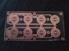
-
Hey all! I finally managed to get everything together over the weekend and get my midibox64 triggering stuff on my mac. I currently only have a DIN module connected to the core, so have grounded all the AIN pins etc and it's connected over USB to the GM5. I've worked with both an edited configuration and the default, but with the same results so far. If I make a connection between the DIN J3's pin D7 and Vs it'll say something about the Bank's etc on the LCD, but I can still assign that to a MIDI command in Traktor, yet none of the other pins will work, even if I set the number of buttons to 4, 8 or 32 in the asm config. I've also had a look at the section that deals with the bank menu buttons, but nothing seemed to correct. How can I go about changing the config to just make all 64 buttons be MIDI triggers and forget about the banks? The way I've done the layout means that I won't have to swap the MIDI layout at all. Any help would be amazing! Even if you just have an asm to look at that works with a similar setup. Thanks Christian
-
I was being stupid! According to I was supposed to connect the GM5 to J2 of the core, not J1. Sorry about that! Lets hope that fixes a few things then ;) Christian EDIT: Got this working last night and re-uploaded the MIOS, so thanks for everyones help! Love you guys!
-
Hey Guys/Girls, Ok I've gone through all the checks and they passed. I couldn't check the ground of the power supply of J3 (see diagram), the one at the top, as I couldn't track it down on the board, but everything else returned 5v. Anyway, while connected to a 9v AC/DC adapter the core returns 5.05V at J2 as it should (and an LED connected to J12 will flash every few seconds). But if I connect it up through the GM5 it only puts out about 1V at J2 and the LED at J12 doesn't flash any more, yet the power out (J7) of the GM5 is outputting 5V. Is there anything I should change in the core's power handling etc? I was about to purchase a few new cores, I need at least one more anyway, but I don't think that'll help at this stage, so any help, as always, is very much appreciated. Thank you Christian
-
Thanks LyleHaze I did the MidiLoop thing using just the GM5 and it worked (although the LED is still not working, could this be down to the resistors I used?). I just sent an LCD message from MIOSStudio and it received it back. I'm going to do the troubleshooting page now, but one thing I've noticed is that the LCD screen wont light up unless I connect the out to the out (guessing it's something to do with ground...). If you look at the attached gif, you can see how I've connected them up, which I believe is now correct, but there is no response from the screen. Should I hook them up as I've done, but cross over the ground line? Sorry for all the questions, I'm just a bit lost at the minute and need to get back on track. Thanks Christian
-
Sorry can I just confirm with someone that my wiring is correct of the GM5 to the Core (I don't think it is)? Should I be considering the GM5 as a MIDI Interface, so the MIDIOut of the Core goes to the MIDIIN of the GM5? I think I've wired the In>In and Out>Out... I'll be going through the troubleshouting in a few hours when I get home. Fingers crossed I can find out whats wrong with it and fix it! Thanks Christian
-
Thanks Thorsten! I'll check these out tomorrow night and report back. As for the GM5, yeah I've checked polarity and also that the LED works. I accidentally ordered some Carbon resistors, but they all seem to work as it appears on my mac etc.. I don't really need the LED, just want to make sure everythings working ok. Later Christian
-
I think my Pic is dead! I had it communicating through MIDI cables connected to an AXIOM25 keyboard. I did a bit of fiddling and think I wrecked one of the MIDI ports I was using as when I tried uploading a Hex file it gave me a MIDI Error and the LCD went blank afterwards... Now I've hooked up a GM5 (not sure if its wired properly, can you check attached image, the midi wires are twisted a half turn), but have tried every combination. It shows up on OSX in MIDIRouting, so think it's working fine. Nothing I do will bring it back to life and even turning the LCD pots doesn't have any effect even though its lit, is this cause there's nothing being displayed? I'd have still thought there would be some change! In MIOSStudio I get: timestamp [unknown] | SysEx: F0 00 00 7E 40 00 02 00 00 00 00 00 00 F7 Any help would be amazing! I'm completely lost! Thanks Christian P.s. On a side note, the GM5 seems to be ok (shows up on the computer and powers the LCD) but the LED I've hooked up to it doesn't light up. Is this meant to be on whenever it's connected to the computer? Cause thats a bit of a worry if it is!