MONSTA
-
Posts
87 -
Joined
-
Last visited
Content Type
Profiles
Forums
Blogs
Gallery
Everything posted by MONSTA
-
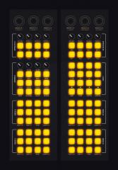
OK here's the new design. This time is two layers, Red on top, Black on the bottom. Looks like what other people have been doing, so think it's ok, but just checking. It'll be my first attempt at a custom PCB so I expect it to go horribly wrong! LOL. Will be trying it this weekend, so just checking if this is 100% right. Thanks Monsta P.s. Does it matter which way vcc and vss are wired in? Or is it only the middle pin thats of any importance?

-
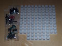
From the album: Monsta
All the bits for my 2 controllers from Sparkfun -
From the album: Monsta
Sparkfun Button Pad Circuit design. -
From the album: Monsta
2D Mockup of my Controllers based on the MIDIBOX64 -
-
Dam! Thought so! Thanks guys, looks like I'm either going to have to do a double sided board, which I was going to try and avoid for my first go, or do it on one side and use some insulated wire for the VS etc... Cheers Niietzshe
-
I am about to start creating my own PCBs and was wondering the best way to wire Sparkfun Pots. I've seen the way people have been wiring pots here and they chain the vs and 5+ separately. Can I just chain 4 together with one loop going from 5+ through all the pots and back to vs (see image)? Also, can you wire these either way or are they polarity dependant. I apologise if my terminology isn't correct and you can understand what I'm saying. Thanks Niietzhe P.s. I like the new Forum! Nice one!!!

-
Thanks for your help! Has anybody got any idea how to go about this? Can it be done with software wiring in MIOS studio, or is it a hardware thing? I'm currently running it through an Axiom25, but have the GM5 chips here, so I'll have to get those soldered up... I never upgraded my girlfriends computer to SnowLeopard, so I'm going to try it on hers tomorrow which should be the same setup as last time. Thanks Again, I'd be completely stuck without help on this one! Christian
-
Hey everyone, I have just come back to this project after a few months off. Previously I had uploaded the MIOS to my 64Core, currently it shows this on the LCD: [int] N ........ (squares with the first one flashing) Reverb # 1 64 I am now on a new instal (OSX Snow Leopard) so did everything from scratch again, this time having to use Mandolane for Java support (demo). MIOS Studio seems to work ok, being able to send messages to the LCD screen, but trying to upload Hex doesn't work. If I tick "Wait for upload request before starting upload" it never gets accepted, nor sends anything over to the core... Any ideas of how to get this going? It's worring me a bit. Thanks for any help. Christian
-
Need a little help with configuring asm for testing (UPDATE)
MONSTA replied to MONSTA's topic in MIDIbox Tools & MIOS Studio
Ok wicked. So I'm going to connect my full DIN to just one button soon and see how we get on :) Thanks for the info! -
Got them through yesterday, thanks TK!
-
Need a little help with configuring asm for testing (UPDATE)
MONSTA replied to MONSTA's topic in MIDIbox Tools & MIOS Studio
Ok I've been away from this longer than I would have like, but I'm finally back to testing. Before I go and ruin anything, I've got my Core and one DIN module with only one button connected. Do I need to remove all the other chips and ground unused pins back to VS (while using this srio_interconnectTest)? Or am I good to go with leaving the chips in and not grounding anything? Thanks for any help, I hope to get it all going over the weekend! -
Woop! Thanks for letting me know! It's a good job because I just went and photoshopped up a circuit board for it (based off Exported Eagle images, so should be to size etc). See attached. For all you DIY Etches, is this going to be possible, or are the tracks too fine? Theres room to make them bigger really, so I could do that. IF DIY is possible, I was going to head down the route of Laser Printer, would this be ok, if not tedius? Or should I really be looking at exposing the boards? Thanks for all your help guys/girls! I'm starting to see the end of the tunnel. Christian
-
Hey everyone! I've never made a PCB before, but need to create some for my Sparkfun Buttons: http://www.sparkfun.com/commerce/product_info.php?products_id=7836 For use with the DIN Module for a Midibox64, is the attached image going to work? It seems like it would, but am I missing something? Like resistors or it's just completly wrong etc... Thanks for any help. Christian
-
Thanks Thorsten! I'll post pics of my build as soon as it's sorted! Christian x
-
Nope, mearly asking if there's an estimated time... As in are we looking at a few weeks or a few months. TK if you did happen to take that as badgering I appologise. I know that you're doing all this to only further the community, not your own wealth and it's very much appreciated, so I would never go out of my way to badger you or anybody on this forum and hope it wasn't taken that way...
-
Any idea when these might be ready yet? I'm dying to get this show on the road ;)
-
Wicked! I might add a few more onto the list then, but I only need two of each, think I've got 5 chips and 4 pcbs just in case :) Thanks for sorting out the "Special Arrangement", I was starting to worry that I'd never get the USB bit sorted! Let us know whats going on Niietzse
-
Need a little help with configuring asm for testing (UPDATE)
MONSTA replied to MONSTA's topic in MIDIbox Tools & MIOS Studio
Thanks! Yeah everything works ok without the DIN module connected, I'll try that test application tonight. Thank you very much! -
Need a little help with configuring asm for testing (UPDATE)
MONSTA replied to MONSTA's topic in MIDIbox Tools & MIOS Studio
Anyone? A point in the right direction would be helpful, I'm going no-where at the minute, but will give it another go. -
Hey people, I'm making a MidiBox64 and have built a PIC based Core (with LCD) and 1xDIN Module, uploaded the MIOS and installed the midibox64 app. Originally the LCD just cycled through a hundred messages a second, so had to edit the asm file, compile the app again and upload it. Now I get: int N and a load of squares, the first of which is flashing on the first line, then on the second I get: @Reverb # 1 64. I've tried with a piece of wire to make the connection between several posts on the DIN and the corresponding ground (vs+d4 for instance), but can't get it to send a midi message (whats the best app to use for OSX that will monitor MIDI, instead of me jumping into Traktor and pressing the midi learn). I've attached the asm file I'm using, if one of you wouldn't mind having a quick look at it to make sure I'm not being stupid, or give some advice on which posts to test. I just want to get one button setup to send a message to my computer then I can continue with the project. Thank you very much for all the great info here, as well as the replies to peoples questions in the forum, i've spent most of my time trauling those for information. Any help would be greatly appreciated. Thank You Christian setup_midibox64.asm setup_midibox64.asm
-
Ok so I can just tell "snapshot" to do whatever I want, it's not a specific function... Thanks for the help! I'll be connecting the first buttons up tonight to see if I can get it to trigger some tracks :) Fun times!!!
-
Hi everyone, I'm just starting to think about some custom PCBs (as well as some test buttons first) for my MidiBox and need to make sure I'm on the right track. Looking at this: http://www.ucapps.de/mbhp/mbhp_dinx4_32buttons.pdf Can I wire up my buttons in strips of 4 using each vs pin? So four buttons connected to pins 1-4 and their grounds connected back to vs on each strip? Instead of only using the vs on J5 and J6 in a chain? May I also ask while I'm on the subject (and pardon my lack of knowlege, I am learning electronics as I go), what is the difference between the #numbers and the others? Can they still be used the same way? Why are some called snapshot, exec, right, left, F1, F2 etc.. and the rest are just numbered? Thanks for any info, I'm progressing quite quickly with my project, but don't have any prior experience to make judment calls. Christian
-
Hey everyone, I've just completed my first core and everything seems to be going fine, apart from this nagging feeling I have about LEDs. My controller will have 47 buttons and 14 pots (61 total). Each button is going to be illuminated with a single colour LED that I want to be able to control with the software (traktor). How are these connected? Am I going to have to hook up a second core to do this or am I missing something? Thanks Christian
-
Hey guys, I managed to successfully get my midicore working (well the LCD is saying READY), so all good there. The Audio8DJ doesn't work with SysEx messages, I'll add it to the blacklist, but my axiom25 worked fine (maybe it's a good idea to have a list of interfaces that does work). On the point of the blog I mentioned, I will of course add to the wiki when appropriate, but the point of the blog was to just document the making of my own controller and give a bit of an idea of how it is made. So things like, to start I got this kit from Mikes, it includes a core that does this, a couple of douts that do that, a GM5 to make it into a USB device etc. I won't be linking specifically to mios files etc, just mention that I had to upload the mios and what it is, with a link to the main download page here and the wiki page on it. Is this ok? It'll be pretty non specific, just bits and pieces of information on what I'd just done, how and why to give people a bit of an idea and send them back here for digging more. Along the lines of this one: http://noofny.blogspot.com/ I only read the first few posts of there but it helped me understand the process a lot and convinced me to go out and get the kit from Mikes. Christian