

findbuddha
-
Posts
267 -
Joined
-
Last visited
Content Type
Profiles
Forums
Blogs
Gallery
Posts posted by findbuddha
-
-
Echo,
Wilba’s PCB is designed exclusively for the button pads available from Livid.
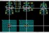
I will design a PCB as you suggest, with 3mm LEDs, 6mm tacts (probably Panasonic LTS). LED will be ‘sitting’ on the switch base, as close as possible to the actuator. The actuator will be just tall enough to use a flat DIY button cap for illuminated button goodness, or it should be possible to drill your own separate LED and switch holes. I’ve attached my draft arrangement of switch/LED/diode. I’m waiting for TK’s ok on my alternate schematic.
The BLM16x16 requires its own Core8, and 5x BLM_Scalar modules (analogous to DIN/DOUT). The BLM is connected to SEQ via midi.

-
My plan with the tactile switches would be to do similar to TK's DIY approach, but with laser cut acrylic caps on top of the silicon sheet. They could be engraved/infilled, and even swapped around if I decide to change button functions.
The specific switches I'm looking at could also be used 'non-illuminated', with the actuators and LEDs sticking through simple drilled holes in a panel.
-
Here's the full size image of the schematic.
-
I was already planning to use 3mm LEDs. It also would require some slight twisting of the leads so the lead spacing is smaller, 3mm bicolor LEDs typically have 0.1" spacing, meaning the outer leads are 0.2" apart, plus width of leads, this is too close to the inner edge of the conductive rubber ring. My current LED footprint has 0.0625" spacing, so outer leads are 0.125" apart. Pads are 36mil x 56mil round. No conflict with plated contacts on PCB which has inner diameter of 0.2" (same as conductive rubber ring on the button pad).
While I haven't proved this yet, I think you would need some ultrabright waterclear bicolor 3mm LEDs, like found on eBay... and not the weak diffused kind like you find at Mouser (and what I used on my MB-SEQ). SMD LEDs might work but it's too hard to find them with good brightness and low cost, plus they might not illuminate the cap as well as a 3mm LED which is more in the middle of the hole. 3mm LEDs are cheap and available from many suppliers so that's good. It's bad enough to lock into one design/supplier of the rubber button pads.
Even with 3mm LEDs, I still needed to do some tricks with the layout... like taking off the top layer pads, because 3mm bicolor LEDs are typically not soldered so close to the PCB, as the leads are so close together and have stupid right angle bends in them, the outer leads would touch a top layer pad around the middle lead. But when you think of the history of 3mm LEDs, they came from a time when single layer PCBs with wire jumpers everywhere were the norm... :wink:
Kingbright have a 3mm LED with narrower spacing available at Digikey: WP3VEGW
It's still diffused though.
Is this the sort of thing you mean from ebay? http://cgi.ebay.com.au/500-3mm-Dual-Bi-Color-Red-Green-Bright-3-Pin-Led-RG3L-/300365559276
As far as I can see it's common cathode, bright and with clear lens.
I'm becoming less convinced about the benefits of the livid pads, at least for my own use.
- Inflexibility of the layout
- Limits use to buttons from one vendor, as Wilba mentioned
- Cost - I'm going to need at least 300-350 buttons for my control surface + BLM
--- Livid pads 5x (8x8): $150USD
--- E-Switch TL1105BF100Q 300x: $30USD
--- Panasonic Light Touch Switch EVQ-PAC09K 300x: $56.70USD
So, people who have the livid pads: do they feel GOOD?
:)
-
GIMP managed to convert it - here's the schematic in one image file. Also includes some 'do not connect flags' that I had omitted.
*Attach files isn't working now*
-
Schematic done, except for labelling each component, and adding connector between the right and left sections of the extra row. I’ll leave those things until I get the green light.
I’ve attached the Kicad schematic file, a SVG export and screenshots – Inkscape crashes when I try to export to a more friendly format.
-
OK, that certainly looks different to the one I’ve got. I just tried it in Eagle Light instead of Kicad and I see what you got. There must be something going wrong with my conversion from Eagle library to Kicad for the round ones.
I’ve sent Livid an email asking whether they’ll fit.
-
It’s not the contact on the PCB I’m concerned about, it’s the hole in the button. The ‘inner circle’ (which I assume corresponds to the size of the hole in the button) is the same in both the rectangular footprint and the circular footprint (both of which are in the livid.lbr.zip).
:)
-
I’m nearly finished the 8x8 schematic. I suppose it would be possible to use Livid’s PCBs, but a lot of extra wiring would be necessary – certainly not worth the expense or effort.
I will be designing a PCB that suits my own use regardless, but I hope to make it useful for others as well.
I’ll ask Livid if I can buy a cheap sample of the buttons – the default shipping option is way too expensive.
Are people happy to use SMD LEDs if that’s what’s necessary to use the Livid buttons? I’ve never done SMD before, but I think the LEDs I’m looking at shouldn’t be too difficult.
If I’m not happy with the Livid button option, I think I’ll use 6mm tacts (probably Panasonic Light Touch Switches) and 3mm LEDs.
The advantages of this path are:
- more flexible/compact layout possible
- cheaper
- easily DIYable panel
- possible to use silicon sheet + DIY button caps for illuminated buttons.
-
AFAIK, we're only looking at using 3-legged bicolor LEDs for this project.
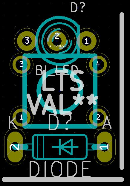
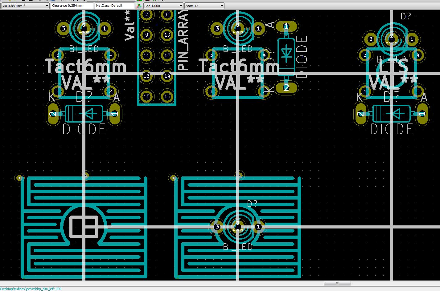
You can see in the last picture I posted, the livid pad footprint on the right has in the center the footprint for the 3mm LED with 3 legs – it doesn’t fit. I think the circular modules in the livid library are for the contacts on the buttons, not the PCB.
Does anyone own the livid buttons to confirm?
-
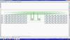
Looks like SMD LED will fit - here's a screenshot of a comparison between a few different layouts/button options on a 19mmx19mm spacing grid. The rectangle inside the Livid pad footprint on the left is the dimensions of an SMD LED.
-
Can anyone confirm whether the duo-colour LEDs will fit inside the Livid button pads? The body of a 3mm LED will obviously fit, it's the legs that may be trouble.
This can be decided layout-driven (there are multiple possibilities) - for extra buttons it's only important that each button/LED combination is individually accessible in the matrix.
(I will check your layout once it's finished)
Best Regards, Thorsten.
Thanks, I'll have a crack at it.
Also, what is the max allowed length of connections between BLM_Scalar modules, and between J3,J4 of Scalar module and J3,J4 of BLM?
-
Gold Phoenix? I'll need 2 of their 14.5"x10" runs.... it's not necessarily a problem as I've got smaller boards to fit on there too, but if there's a better option?
Thanks
-
Thanks, I've sent MEC an email to enquire about samples and pricing.
Price is definitely a factor - I'm going to be needing ~400 of them.
-
What are your experiences with 6mm switches?
I'm looking for quiet, I don't mind if there's a physical sensation.
So far I'm looking at:
E-Switch TL1105 eg: TL1105SPF100Q
Panasonic Light Touch Switch eg: EVQPAC07K
I've got a sample of TL1105SPF100Q and EVQQ2F03W (Panasonic LTS in SMD, I couldn't get the other version to sample cheaply).
The Panasonic is quieter than the E-Switch - I assume the SMD version will sound the same as the through hole version.
Of course, putting the buttons under 2mm silicon sheet () may reduce the noise substantially?
:)
-
Ok, I’ve got 4 quadrants done:
A1->H8 and cathodes EC1->EC8 connected to J3_1,J4_1
I1->P8 and cathodes EC9->EC16 connected to J3_2,J4_2
A9->H16 connected to J3_3,J4_3
I9->P16 connected to J3_4,J4_4
Can you please explain the connection of the extra column and row to J3_5,J4_5?
-
Design is progressing..... though I haven't gotten to the hard part yet. :frantics:
-
In this case it could be a good idea to change the matrix structure to 8x8 instead of 16x4.
This would give us 4 quarters, and between these modules there are only the SRIO connections to BLM_SCALAR modules.
It would require some firmware changes, but so long only a second variant is required to simplify the HW, it would be ok.
TK, do you plan to create this schematic?
I have my new monitor now, I will start PCB and frontpanel design work soon. I'll start with the BLM_SCALAR modules.
:)
-
Any Aussies (and Kiwis) needing an ENC28J60 source can piggyback onto my next Mouser/Digikey order.
Maybe I should just get all the parts for the MBHP_ETH module in bulk... some of the other parts would be hard to find here.
Does anyone already have a BOM for Mouser?
This is the one I've put together, haven't ordered yet - I'll probably put it in with parts for a 16x16 BLM. Might be best if you check it, in particular I think I wasn't sure of the Magjack.
Ethernet IC 579-ENC28J60/SP 1 $4.90 $4.90
magjack? 523-RJHSE-5381 1 $1.58 $1.58
25mhz crystal 695-HC49US-25-U 1 $0.78 $0.78
ceramic cap 18pF 140-50N2-180J-RC 2 $0.10 $0.19
ceramic cap .01uF 140-50Z5-103M-RC 2 $0.14 $0.27
ceramic cap .1uF 140-50U5-104M-RC 3 $0.30 $0.89
tantal cap 10uF 80-T351E106M16AT 1 $0.70 $0.70
electrolytic 100uF 140-LLRL16V100-RC 1 $0.46 $0.46
2.32kohm metal film 1% ¼ watt 271-2.32K-RC 1 $0.18 $0.18
49.9ohm metal film 1% ¼ watt 271-49.9-RC 4 $0.18 $0.70
220ohm metal film 1% ¼ watt 271-220-RC 2 $0.18 $0.35
ferrit bead 10uH 434-22-100 1 $0.27 $0.27
2x5 header 517-30310-6002 1 $0.55 $0.55
-
Maybe it would be more practical/functional to have the BLM LCDs running from the BLM core?
I still don't want duplicate LCDs for myself though :)
-
TK, do you think 3mm LEDs would work alright with your illuminated button concept?
I see a possible configuration:
Switches: E-Switch TL1105SP - 7.5mm to top of actuator.
LED: 3mm duo as used in Wilba's CS order. Mouser: 859-LTL1BEKVJNN - 6.7mm min height.
Button caps: There is a matching round cap for those who want to drill their own panels, Mouser: 612-1R-BK, and also other shapes.
It would also be possible to do a solution like TK's cheap illuminated buttons. Also I'm thinking it might be possible to use the silicon sheet, and have nice looking laser cut acrylic glued on top as buttons instead of the rubber feet. This would hopefully give a nice feel.
:)
What's everyone think?
-
Hi, which part number?
Would you consider selling me 32? What price?
Thanks
-
3. When i buy the STM-board in SmashTV's shop the bootloader is already programmed. But where can i find the (template) software for the STM32?
http://svnmios.midibox.org/listing.php?repname=svn.mios32&path=%2Ftrunk%2Fapps%2F
There's a tutorials folder. :)
-
TK, as the only person who has both the big BLM and the SEQ, do you think this is the optimal layout?
Of course the extra encoders are optional, and could be replaced with each individuals choice of encoders/pots/buttons/faders. But at least it will settle the layout for the main SEQ panel.

MBBLM schematics and PCB discussions
in MIDIbox BLM
Posted
Wilba, or other PCB masters: Looking at your layout here, I see that you've got 2 separate boards (4x16, 1x16), with pads right at the edges to connect the relevant traces. Is it feasible to get this manufactured in a single job? Is V-score or Tab routing best for this situation?
It seems to me a way to avoid set up fees of 2 separate jobs. (I'm a PCB newb)