

findbuddha
-
Posts
267 -
Joined
-
Last visited
Content Type
Profiles
Forums
Blogs
Gallery
Posts posted by findbuddha
-
-
Not sure about everyone else, but I can't afford duplicate LCDs.
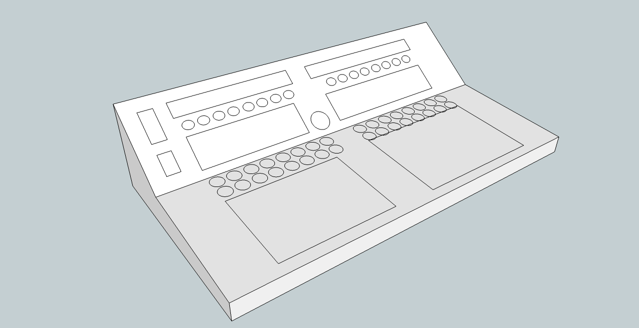
Here's a quick sketchup of how another layout may look. Regular SEQ panel on top, BLM and 2x16 encoders on bottom. The SEQ panel need not be angled differently, but I think this may improve visibility and reachability.

-
The first has the whole sequencer on top of the BLM, because i think the LCDs and the encoders should not be too far away from each other, it's more intuitive that way.
Yeah, I'm not sure what's the best way with that - I'm thinking it might be best to be able to see the BLM while using the control surface? I don't know.
In the second I added 3 rows of encoders which could be used to directly edit gate, velocity, length, etc... this would allow a very nice workflow without having to switch which parameter to edit. Would that be possible? The whole thing might get too big though....
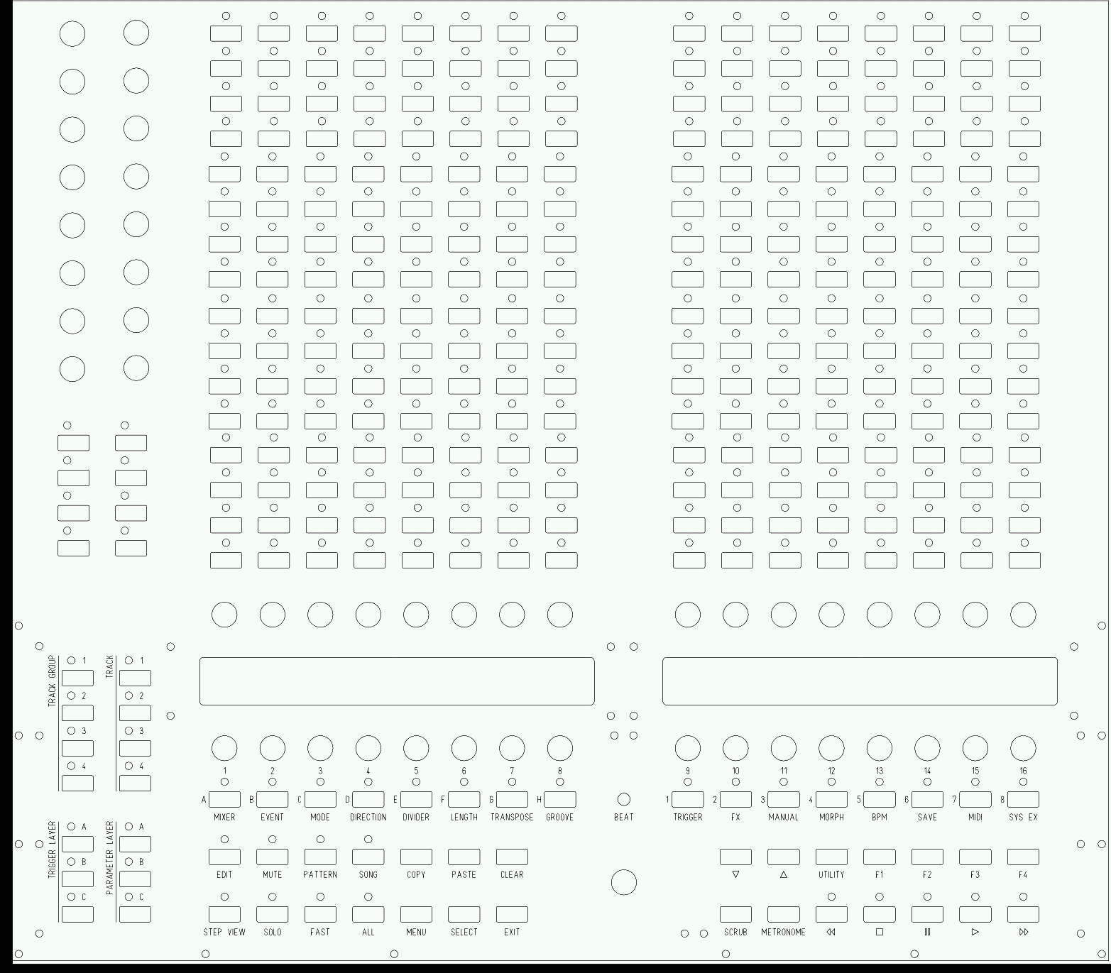
Wilba's PCB uses 6 DIN shift registers, so we have 10 left to use. 16 encoders use 4 shift registers, so we can only have 2x16 encoders, plus some buttons (or a few more encoders). This would still give 3x16 encoders in total. I've attached another image of how it might look. I would use a couple of buttons to assign different parameters to each row of encoders, eg. 3 buttons: EncRow1 Assign, EncRow2 Assign, EncRow3 Assign. Press the assign button, the options come up on the LCD, select with the matching general purpose button.
Having the encoders lined up horizontally will make the panel too tall to fit in a single ponoko sheet, there's only 384mm to work with. While this will raise the costs, it's probably worth it to have the more optimal layout.
Perhaps it would be good to split the panel into 3 parts, horizontally between LCDs, BLM and encoders. This would have the benefit of allowing people to rearrange the panels as suits them. I'm not sure how to manage the aesthetics of 'joining' the panels. ;) Perhaps Ponoko bamboo would look nice in between.
:)
-
For those who haven't seen this thread: I have volunteered to design a PCB and matching panel. There are a few example pictures further down the thread.
Some notes:
- I intend to design it in a way that will fit in a single chassis with Wilba's control surface PCB. This is my ideal scenario, as I already own this PCB and I haven't paid for front panel yet. It will however be simple to offer a modified version for standalone use. If I can find a free DXF editor I'm comfortable with (or get Inkscape's DXF export to work) I'll provide DXF files for those who don't want to use Ponoko.
- My intention is to use the same button(TL1100F160Q)/cap(611-PEBK)/Bi-LED(859-LTL1BEKVJNN) combo as in Wilba's CS (mouser part numbers). I will consider adding additional footprints to the board, but will keep expense and usefulness in mind. Personally, I can't afford ready-made illuminated buttons of decent quality. Ideally I'd like the quiet ones described here: Seems that group buy died unfortunately.
- I want my BLM to align with the buttons and encoders on the control surface. People who want a standalone BLM may want the 'square' format. I propose a BLM PCB that is (or can be) split down the vertical centre. This will allow both layouts. From looking at the schematic, each 16x4 section will require 31 wires to jump the gap.
- I propose to have the BLM_Scalar module integrated on the button PCB. As with the above suggestion, I'm assuming this is feasible but I'm not experienced in such matters.
- I have no experience with actually producing PCBs or panels. I have gotten the hang of both KiCad and Inkscape, so I think I will be able to achieve this with a few pointers from more experienced people. If any experts wish to take up this project, I'm happy to defer to them.
Please offer your suggestions! I'm stuck on a 13" screen until the end of the week, so probably won't start work until then.
:)
-
If you're asking those questions you're going to need to do a lot more reading, both on this forum, the wiki and at ucapps.de
The midibox platform (MBHP) runs applications on either a Core8 or Core32 module. Check this page http://ucapps.de/mios32_download.html for a list of released applications for the Core32.
Check this page/folder for code/apps and tutorials. The tutorials are good! http://svnmios.midibox.org/listing.php?repname=svn.mios32&path=%2Ftrunk%2Fapps%2F
This page will explain setting up the toolchain: http://www.midibox.org/dokuwiki/doku.php?id=windows_mios32_toolchain_core
-
Is it case sensitive?
-
Those are the instructions for the Core8 toolchain. For Core32 see here: http://www.midibox.org/dokuwiki/doku.php?id=windows_mios32_toolchain_core
-
But there are some things that need to be considered: you placed the BLM at the top of the panel, which means that when you are pushing buttons you won't see the LCD output.
But for some BLM modes it might be important to get a direct response from the LCDs. Therefore I propose to place the BLM below the common control surface.
The 16 "extra column" and 16 "extra row" (I haven't found a better name yet) buttons/LEDs are missing.
They are important to select modes/tracks/step views and maybe other features (like loops, sections, parameter/trigger layer, octaves, special effects) directly.
Also the "shift" button is not there (lower left corner of my BLM16x16+X) - thats one of the most important buttons to control the entry.
E.g., pressing SHIFT will allow you to select the BLM mode with the 16 "extra column" buttons that are normaly used to select and mute tracks.
It will allow you to accent steps with the BLM in pattern edit mode.
etc.
I've attached an updated example - unfortunately it won't fit with the extra column/row to bottom/left while maintaining alignment, so I've put it on bottom right. There's a bit of the control surface PCB that's in the way.
Will it be possible to leave some 'mode' buttons spare (in the extra column/row) for the user to add extra features in their firmware? I want to add a mini-Logic Control, perhaps using the bottom few rows of BLM for Mute/Solo/Rec/Select and the top rows as VU meter.
It requires a PIC based MBHP_CORE module with the "blm_scalar" firmware: http://svnmios.midibox.org/listing.php?repname=svn.mios&path=%2Ftrunk%2Fapps%2Fcontrollers%2Fblm_scalar%2FI consider a PIC18F4550 based USB option as well, but I'm not sure if this is really for interest...
Communication between MBSEQ V4 and BLM is done via MIDI.
The protocol is documented in the README.txt file of the application - it's really fast!
And it's generic enough so that the BLM could be controlled from other applications (e.g. PC/Mac based) as well.
The MBHP_CORE_STM32 module has some spare "midi" Rx/Tx ports available on the JTAG connector, one of them will be used so that no common MIDI IO pair has to be sacrificed.
I think so long as data and power can be interfaced within the same chassis as the SEQ modules, no USB option would be necessary.
If somebody could create a PCB for the matrix (once schematics are available), it would be very helpful.
I'll be happy to create a PCB and panel to match with Wilba's CS PCB - I'll need some experts to take a look at it before any money is spent though :)
-
Ah ok. Well at this stage, if I do end up putting the BLM on the same panel as the SEQ control surface, I want the BLM to line up with the existing GP buttons. I'm not sure if TK's solution will allow that.
-
See http://midibox.org/forums/index.php?app=gallery&module=user&user=3436&do=view_album&album=51 for what TK's up to.
I'm awaiting more details of the project, like a schematic - I'm not sure if anyone else is designing a PCB for it, so I've been having a fiddle with KiCAD. I'm pretty sure it'll fit on one of Gold Phoenix's 14.5"x10" boards.
-
Here's a quick mockup of a panel with the default SEQ/Wilba control surface, a 16x16 BLM, and 2x16 extra encoders + a few buttons for DAW/synth control. This is using roughly the max height available from Ponoko's materials (384mm), considering the width of the control surface PCB requires the panel to be oriented this way. Ponoko says: USD$78.77 ex shipping.
-
I assume you mean Wilba's control surface PCB?
AFAIK it's not necessary to do anything with those - mine works fine.
-
I'm in New Zealand, would consider ordering a few of these to send out to people if we could agree on a fixed format.
Question: I think I remember a clear acrylic WilbaSeq panel a while back, is it robust enough to handle JB weld? Or judging from your drawing were you contemplating normal panel screws?
Might be useful putting a thread in the Bulk Orders section?
I don't have the PCB yet; I'd need one at some stage ;)
I was lucky enough to get the last PCB from the last order....
I was planning to use through panel screws. I don't mind (black) screw heads visible. My entire enclosure will be made from ponoko materials, so there's currently space around the edge of the panel to allow for screwing onto the 5.5mm bamboo.
As far a group buy goes, I'd be happy to be the guinea pig and pay for the first/test panel, but I think I'm going to have some additional holes in there that other people won't want. There's quite a few DIN/DOUT spaces left after Wilba's PCB takes its share, and I'd like to use some of them. I'm currently thinking 32 encoders for DAW/Mixer/Plugin control, and a few buttons for choosing the functions.
-
I'm still yet to finalize my files, but I just ran a test through with this panel file in 3mm black acrylic, lcd windows in 3mm clear acrylic, and some simple end pieces of 5.5mm natural bamboo. Total came to $100 USD, shipped to me in Australia, from the ponoko hub in New Zealand.
I'm still pondering adding extra buttons and/or encoders to my panel, for custom functions like VST or DAW mixer control.
:)
-
Thankyou!
-
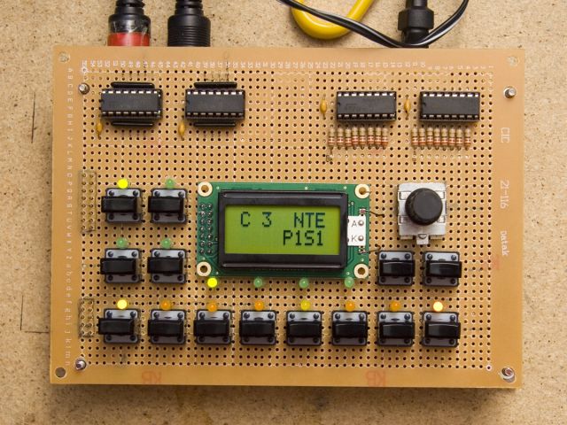
Get a 1.3mm drill and off you go. Do you already have the switches? Cause sometimes the pins aren't really quite as big as it says in the datasheet.
I don't have all the switches, I just bought a few to sample. Thought that was best before I buy 256+ for a big BLM/control surface. :)
I'm surprised it doesn't fit... this switch is the one I use a lot (MB-SEQ, sammichSID) and it seems to fit my prototyping PCBs nicely.
 You probably don't even need a drill bit, just using the tip of a craft knife should be enough to widen the hole just enough for the pin.
Wilba, where do you get your protoboards? The typical aus stores don't seem to sell pad-per-hole stuff. I'm looking at this stuff at the moment: http://cgi.ebay.com.au/5PCS-CIRCUIT-PANEL-PCB-DIY-Prototype-Board-180x300mm-/170447513484, or this stuff: http://cgi.ebay.com.au/Prototype-Circuit-Board-23000-pad-per-hole500x300mm-/150394989810, but I'm a bit worried about such a large sheet breaking in transit.
You could also use a small screwdriver to widen the holes.Best Regards, Thorsten.
Thanks everyone for the suggestions, I'll give it a try :)
-
Check http://ucapps.de for an idea of what modules you'll need, and http://www.avishowtech.com/mbhp/ for PCBs.
Looks like you'll need to do some custom coding, check http://svnmios.midibox.org for tutorials, examples and the existing apps.
Probably best to start with a Core32, has inbuilt USB connection and AFAIK coding should be easier.
Unfortunately you'll have to do hours of reading :) :frantics:
-
This may be a silly question :)
I have some E-Switch TL1100F160Q. Datasheet says they need a hole ~1.3mm diameter.
They won't fit in the holes of the scraps of protoboard I have....
Is it possible to find pad-per-hole protoboard with big enough holes, or should I choose a different switch?
Failing that I get custom PCB made - I was going to do this anyway until I found out that gold phoenix can't do big enough for what I want (in one order).
Cheers! :sorcerer:
-
-
I notice the OPL3 PCBs are sold out at SmashTV's shop - can we assume they'll be back at some point?
-
The bicolor LED issue has discouraged me from using any of the pre-made button pad PCBs - how do you plan to overcome this?
:)
-
I'm not sure if I still need a HW based BLM for myself anymore.
The main advantage of the SW solution is the flexibility - you can quickly change the application to use the device for a different purpose, accordingly it saves some place on the desk.
I understand what you mean - software is so flexible. I wonder if the responsiveness of the iPad's touchscreen will provide for a satisfying experience? I assume it will be fine for non-timing critical button pushes, not sure about things like virtual encoders and XY pads etc. This also requires good latency from the WiFi OSC connection.
Unfortunately for me I think the iPad will be more expensive than a hardware 16x16 BLM (discrete button + led, not illuminated buttons), and I have no other reason for getting an iPad. :frantics: I'll have to work out total cost of all buttons, leds, PCBS and extra panels/casing from Ponoko.
If I'm going to buy a tablet device I'd also like better connectivity options than the iPad offers - we'll have to see what HP, Google etc. bring out.
Do you still plan to add the code to support the hardware 16x16 BLM?
Cheers :)
-
TK,
I'm curious how you see the role of touchscreen devices for the purpose of implementing largish BLMs (say 16x16)?
I've got my SEQV4 nearly finished (just waiting on front panel/case), and I'm not sure in the future whether to choose hardware or software BLM.
Also I wonder if there will be cheaper touchscreen devices than the iPad, that still provide a useful interface.
Cheers :)
-
Ok, hopefully final draft now. I've enlarged the panel to include mounting room for desktop case.
-
Can someone please give a quick look over this svg? Any tips would be appreciated.
Mostly it is a direct conversion of wilba's 17" dxf. I have removed the 'extra' ring around the mounting holes, changed the lcd windows to a simple cutout, and widened the vertical spacing of the lcd mounting holes to match the optrex displays I'm using.
I plan to double up the engraving layer before submitting to ponoko. File was composed in Inkscape.
Thanks :)


MBBLM schematics and PCB discussions
in MIDIbox BLM
Posted
The same button caps need not be used with those buttons - perhaps there are circular ones available?