.jpg.be50e340987b4f3feee814022f07387d.jpg)
Adam Schabtach
-
Posts
43 -
Joined
-
Last visited
-
Days Won
2
Content Type
Profiles
Forums
Blogs
Gallery
Everything posted by Adam Schabtach
-
Hi Peter, I wish I had found the problem sooner; I had to delay work on my kit for awhile because of other demands on my spare time. Hopefully I found it early enough that you can contact most other affected customers before they begin soldering. Mistakes do indeed happen--I completely understand. After over 20 years in the music-tech business, and shipping over 40 software and hardware products, I have also handled many mistakes. Thanks for your help. You have a good day, too! Warm regards, --Adam
-
Hah! Okay then. Thanks for the confirmation. I will move on to other parts of the kit and await a replacement for the USB PCB. Maybe I will check for +5V/GND shorts on the other PCBs before I start soldering them. Thanks-- --Adam
-
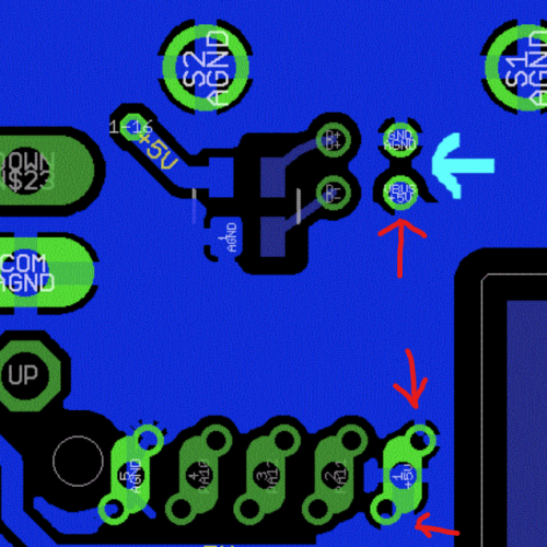
Those are the first locations I checked since obviously they're the most likely to be shorted by a solder bridge. Here's the photo; thanks for looking at it for me. It's possibly worth mentioning that I have a lot of experience with this sort of work. I'm used to hand-soldering 0603s and TQFP100 packages. Obviously there's a mistake somewhere, though. I understand that nobody's board would work if +5 and GND are connected, but you're showing me an image which appears to show that they are connected. Hence my confusion.
.thumb.jpg.d38bab2ae2a40418278fee23ef071a0d.jpg)
-
Thanks. I can post a photo later today, but I'm looking at the PCB artwork you posted, and I am confused because it appears that the +5V and AGND nets are connected together in several places by the copper pour? Thanks-- --Adam
-
Okay, this is sad, but my construction efforts have run into problems at the first test point: loading the firmware onto to the MCU. Eventually I figured out that there's a short between +5V and GND on the USB PCB itself. I finally isolated it to this PCB by disconnecting the ribbon cable between the two PCBs. I've also removed the TVS diode, figuring that it might be the most likely place for a solder short. I've examined my solder joints with a magnifier and microscope(!) and have found nothing. Could I obtain either a schematic or the PCB artwork for this PCB? It would help with locating the problem if I knew which traces are +5V and which are GND. I'm assuming that +5V is on the first two conductors of the ribbon cable and GND is the last two conductors, based on the silkscreen notations near the ribbon cable connector. The next thing I'm going to have to do is start removing parts one by one, which is unfortunate since removing things like the USB connectors will not be easy. Thanks-- --Adam
-
That would be amazing. Thank you!
-
Speaking strictly from a selfish point of view: I built up my MBCV2 with a 128x64 DOG GLCD and an SCS-style panel. I did this because the GLCD fits well in a 2U-wide panel for my 5U-format modular synth, because I wanted to play with one of these LCDs, and because I plan to mostly use the Lemur interface. Hence it would be very useful to me if it were possible for MBCV2 software to use just one GLCD to display both the SCS interface and an oscilloscope. Obviously it would be necessary to somehow switch between these two modes--unless TK wants to be really clever and put the SCS text fields and the oscilloscope on one GLCD. :hyper:
-
Very nice! More inspiration for me to finish my MBCV2 one of these months...
-
Excellent! Note that you probably want to put a jumper between LDAC and GND. I brought this pin out to a test point but for normal operation it's easiest to just ground it. If you like, I will tidy up my code and send it to you privately so that you at least have an example to start with. I can probably manage to do that before December. :rolleyes:
-
As it so happens, I used OSH Park to have those boards made. I've made the design available as a shared project: http://oshpark.com/shared_projects/UYwDVPq9 Here are the DipTrace schematic and layout files: DAC Breakout Board DipTrace Files.zip I can give you the code I've written also, but it is a pretty quick hack so maybe I should exercise it a bit more before sharing it. I would be happy to collaborate with you on an official aout adaptation, though.
-
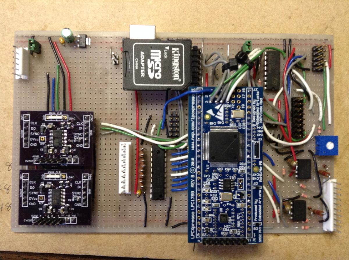
Apparently the remark in my previous post about time was somewhat prophetic, since here it is November and I still haven't completed my MBCV2 system. There have been other unusual events vying for my time and attention, however, such as my company releasing its first hardware products :w00t: , and a major natural disaster hitting the area where I live. :cry: However, my MBCV2 project is approaching completion. Here's a photo of the main board. It's basically the portions of a MBHP_CORE_LPC17 used in the MBCV2 built on stripboard: On the left are two custom PCBs with Analog Devices AD5734 DACs. These are 14-bit quad converters with built-in voltage references and output buffers with adjustable ranges, either monopolar or bipolar. They're kind of expensive but they require less external circuitry. I've added code to aout.c to accommodate them; they're fairly similar to the TLV5630 from a software perspective. I've also built up a SCS-like control panel on another piece of stripboard. The CORE board has connectors for both a character LCD and a DOGM 128x64 graphic LCD. I'm going to use the latter because it fits better on a 5U-tall panel in my modular synth. All of this is working on my bench but I haven't yet tested it thoroughly. The next steps are to connect it to a panel of 1/4" jacks and install it in my synth cabinet. Despite my slow progress it has been a fun project.
-
Hi Thorsten, Thank you very much for the reply. I have an iPad and Lemur, and I just received an LPC1769 LPCXpresso board. (After posting my query I spent more time reading the source code and decided to switch to an LPC17 since that is what you are currently using.) I will start building up a MBCV2 system and let you know how it goes. I know that time is often the most difficult resource to obtain for projects like this! Kind regards, --Adam
-
Could someone tell me about the current status of this project? I've read through this thread, and I've been reading the source code, but I'm still unsure how complete the code is. Also, does the description of the menus and hardware options for CV V1 still apply to CV V2? I compiled the V2 code and it appears to boot correctly on my STM32 core, but MIOS Studio is unable to communicate with the core over USB. (It worked previously when I was running different apps on the core.) I'd appreciate it if TK or someone else could tell me what to expect from the current V2 code. It looks really great, but I'd like to know what I can expect before I start building one of the AOUT modules. Thanks very much for your assistance. --Adam
-
I'd like to ask some advice for connecting more than 64 encoders to an STM32-based core. I'm wondering whether a matrix-scanning approach will not work with encoders, since perhaps contact-change events could be lost during the scanning process. I also need some digital inputs for pushbuttons, including the 64 integral pushbuttons. Those could be handled by a matrix-scanning technique, of course. I'm mostly wondering about the simplest approach for integration with the existing MIOS32 code. Thanks in advance for any suggestions, advice, etc. If this has been discussed previously feel free to give me a link and say, "read this!" While I am new to the MIDIbox community I would humbly say that I have intermediate to advanced skills relevant to this discussion: I have already created my own clone of the STM32-based core (i.e. custom PCB, MIOS flashed into off-the-shelf STM32, etc.) and I have many years of experience developing music-related software. Thanks-- --Adam
-
Thank you! Just in time to provide reading material for a weekend at the in-laws' house, which has no internet connection. :twitch: --Adam
-
Thanks for the replies, Admins. I will be patient. I have a local copy of /sequencers which will keep me occupied for awhile. --Adam
-
Forgive me if this has been mentioned somewhere else already, but it seems that the SVN repository is unavailable. I know it was there a few days ago but since late last night [in US Mountain time] I receive the following error message when I try to access the repository: Warning: proc_open() has been disabled for security reasons in /home/midibox/public_html/websvn/include/command.php on line 122 Error running this command: /home/midibox/bin/svn --config-dir /tmp --version Thanks for your attention. --Adam
-
I am a newbie here also but I wanted to report that I purchased 80 knobs from Simca and am entirely happy with the transaction. The knobs are exactly as pictured and his communication with me was prompt and thorough. I'm a happy buyer! --Adam Schabtach
.jpg.be50e340987b4f3feee814022f07387d.thumb.jpg.ac545b5d5a297af16dccfd611867ac30.jpg)
.jpg.2e6588b4d4ba4ee5620eea717fbdf6df.jpg)