

eptheca
-
Posts
373 -
Joined
-
Last visited
-
Days Won
16
Content Type
Profiles
Forums
Blogs
Gallery
Posts posted by eptheca
-
-
On 17.9.2017 at 2:00 AM, Altitude said:
I think that there is something else pulling it down, I run mine on USB power all the time when I'm flashing it, check resistance between +5 and gnd and +3.3 and ground
Resistance between 5V and G is 938 Ohm, and between 3V and G it's 1,9 K
On 17.9.2017 at 9:54 PM, CJ55 said:Are you using the Micro-USB or the Mini-USB port for powering your SEQ?
I am using the Micro-USB
I think it's down to bad cables, because when I connect my 1,5A phone charger with Micro-USB directly to the Discovery board, it lights up fine.
I have an ebay panel mount female USB A socket connected to a Micro-USB cable where I have soldered a cable to Pin 4 so I can pull it to G for USB Host mode. I think this together with a cheap USB 2.0 A to A cable is the problem.
-
I have now tried with my SONY phone charger that provides 1,5 A, and still no change.
The sequencer is running fine, and all the LEDs are bright, it's only the LCDs
I wonder if is has to do with the way I power them. I have modified the Core like you Altitude. I use the Kyocera LCDs

I can't see how it would be different. It's the same 5V on the same rail.???
I have read about a Data only USB cable, some people use for their audio interfaces.
I might try it. I would like to avoid having a switch on J17 that I could forget to turn off, and fry my computer.
-
I have now tried with a Y cable straight to the computer, but it didn't help.
Also tried with a new USB 3.0 Hub, which in theory should provide 900mA per port, and with a new USB 3.0 cable and the USB 3.0 Y cable from 2 ports which then should provide 1,8A, but still not lighting up properly :(
I guess I need to power it with my 5V PSU, and connect a switch to J17.
Or maybe a USB cable without the power wires? Don't know if that exists or will work even ??????
-
Cool Bruno, I like it :)
-
That is an excellent idea!
Thanks man :)
-
Hi,
Normally I power my SEQ with a 5V, 2,5A power supply connected to J2. I also have J17 closed to provide power to USB gear connected to the USB socket in host mode.
I would like to use it with my computer, and power it over USB, of course without the PSU connected to J2.
I have a STM32F4 core with 2 x MIDI I/O, 2 x IICx4, BLM 16x4, TPD and AOUT_NG.
I have not measured how much current this all draws.
When I connect it to my computer with a Belkin USB 2.0 Hub with external PSU, the SEQ starts up, and runs but the LCD's are very dim, I can only see very little text, and only in the dark.
I assume that the USB Hub does not provide enough current, and that the LCD's are suffering from that.
I can't find any specific info about current per port for this Belkin Hub, but I assume it has some sort of limiter set to the 500mA standard. It has 7 ports, and a 2,5A PSU.
Can anybody suggest a solution for this? Do you know of a specific USB Hub with external PSU and ports without current limiting?
Cheers, Hal
-
On 5.9.2017 at 10:03 PM, fallenturtle said:
Good to know... I assume midibox.org is safe enough. :)
Nope :(
I have had the same type of outrage here on this forum re-using old Sinclair computer cases.
arti492 wrote : You destroyed the ZX Spectrum, you should burn in hell
-
they have the bare PCB as well http://shop.musicfromouterspace.com/cart/Power%20Supplies/MFOS%20Wall%20Wart%20Bipolar%20Power%20Supply%20Bare%20PCB
Aciiiiid post

-
I got this kit http://shop.musicfromouterspace.com/cart/wall-wart-bipolar-supply
It's the one from MFOS you linked to.
I only use it to power the AOUT_NG, so to reduce the height I only use one pair of caps laying down
I used the caps that came with the kit, they are 4700uF
-
SEQ V4 (STM32F4) 092
I have an AOUT_NG connected to my sequencer that I use to modulate some filters.
On one track I have a 128 step CC event with 8 CC layers, one for each CV out.
If I understand it correctly, the LFO effect can only work on one CC layer/number, so I have to have CC values for each step in each CC layer to modulate all 8 CV out at the same time.
In JAM mode I can record CC in as long as the layers are "free", but when I clear a track to record it again, all the CC values resets to nothing, in stead of 0, and I can't record again.
To reset it I have to go to event, change to another, initialize, then change back and initialize.
Is it a better way to do this?
Is it possible to only clear/reset a layer, not the whole track?
Is it possible to "protect" a layer when you record on the other layers?
Or if anyone have another/better way to achieve the same :)
Cheers, Hal
-
Nice build guide :)
-
I use Ray's (MFOS)
I'm not sure of the power consumption, but it's not much. I only use one set of el-caps.

-
I have never used it as an envelope, but like you say it should be possible with CC
I think you can have several CC events on each track and that they can be sent to different CV out
-
 1
1
-
-
Hi,
welcome to the MIDIbox community :)
For LFO set the track to CC, set the CV out, press MENU + FX, choose LFO
you can read more about it here: http://ucapps.de/midibox_seq_manual_m.html
-
Sounds great! Really like that KORG bass. Nice filter
-
I use the Manager together with Ableton. Works fine.
I can send MIDI notes from Ableton, and change parameters in the Manager at the same time.
I have used other similar setups routed through virtual MIDI ports like MIDI Yoke, but it never works properly is my experience.
You said earlier that the Manger runs on ipad?
Does it work on Android?
-
To get this thread back to MB-TIA........
Here is a Q&A I had with Antichambre today:
I have been playing with the MB-TIA today.
I use it with the MB-TIA_Mgr_1cIs that the latest version?I think because I didn't work more on it.
Did you make a Max4Live version, or was that for the POKEY?I tried I think, the difficulty was save and retieve parameters from and to Live because this software filters the sysex messages.I am not sure what all the different settings in the Manager does.Did you write a manual for it?No :) but I can explainLike if I make changes, are they saved in the MB-TIA?Yes after Save press on the right preset.
If i change MIDI Channel for the two Voices, is that stored in the unit for the next time I turn it on?Yes normally it's saved the rom memory portion of the pic, and always read at startupIf I understand correctly, the patches are stored in the Bankstick.YesCan I change between the patches with MIDI CC?Of course, with common program change And one CC for the bank (CC#0).Check the Midi chart, everything is inside:
http://www.midibox.org/dokuwiki/doku.php?id=midibox_tia#downloadsI will post questions here in the future :)-
1
-
-
6 hours ago, FlavioB said:
What do you guys suggest now?
Sell it to someone that can live with it like it is, and build your own like you want it.
That's what I would do, and that's what the rest of us have done :)
-
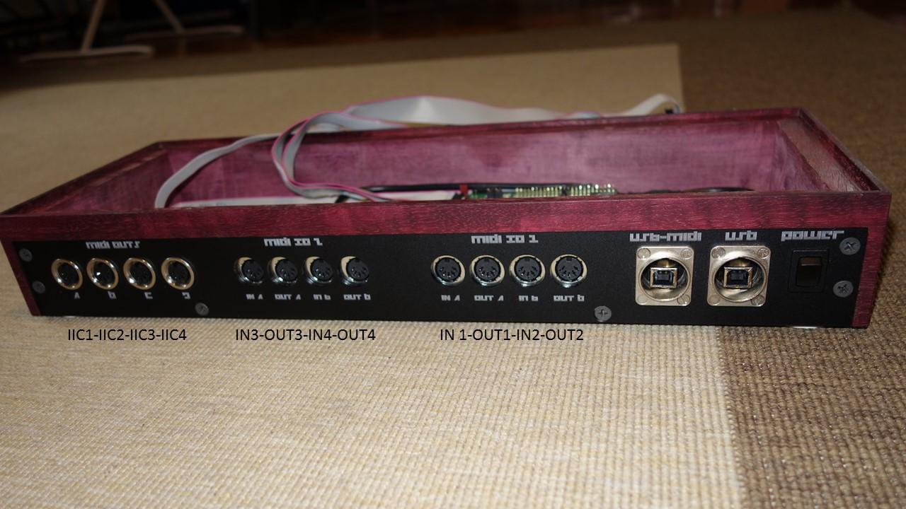
Actually it looks correct to me from the photos. The cable from J11E on the core goes to J1 of the MIDI I/O module to the right seen from the back panel and is labelled MIDI I/O 1, and the ports are labelled IN A, OUT A, IN B, OUT B. Then the cable goes from J2 of the first to J1 of the second that is to the left of the first still seen from the back.
That is how mine are connected as well. The only difference is that mine are ordered from left to right
I am not sure what is wrong?
It all looks very neat & tidy. I don't think =FFW=> has messed up, it's excellent craftsmanship.
Is this the unit in question? It's indeed a premium build!
Are you sure you are not just reading the labeling wrong?
From what I can see, it's correct according to the labeling. The only thing "weird" is the order of the groups of MIDI I/O and MIDI OUTS and the font.
This is how it should show up in the menu according to the wiring and labeling:
-
The best would be to change this in hardware where the fault is. You can change the name in software, but the order would be wrong. You can call MIDIOUT 2 for 1 and 1 for 2, but the order in the menu would be MIDI OUT 2, MIDI OUT 1, MIDI OUT 4 MIDI OUT 3.
Is it just the labeling on the back panel?
Could you provide photos? Is the the beautiful maroon wood case?
Anyway, maybe =FFW=> is the right person to help here ;)
-
In the file seq_midi_port.c in the source files you can change the names
save - compile - upload
-
You're welcome :)
It's a nice opportunity for me to contribute.
Enjoy your LCDs
-
Easy mistake, I did the same.
You need 4x 1K resistors where one side of them is connected to the same point, and they go to each point.
It will not look as neat, but it will do the job.
Here is the part I got in the end
-
I was going to suggest the 4x1K resistor array. I bought the wrong part once, and it was a "series" array and not a parallel that is the correct.
Powering SEQ with USB Hub problem
in MIDIbox SEQ
Posted
It's only about 0,7 Ohm,
I have taken it apart an checked the socket and cable etc, can't find anything.
Then I thought it could be a ground loop through the USB socket since it touches the alu panel, but after clearing them by adding a spacer, no difference.
I have tested with different types of cables, directly to the Disco board, and there is a difference, so it could have something to do with the quality/length of the cable.
Anyway, I have given up and made a "Data-only-USB-cable" so I can power it with my trusty 5V PSU, and connect it to my computer with that. That way I can keep my "USB Host Mode" wiring :)
Thanks for the troubleshooting support guys