

Hawkeye
-
Posts
3,632 -
Joined
-
Last visited
-
Days Won
36
Content Type
Profiles
Forums
Blogs
Gallery
Posts posted by Hawkeye
-
-
Step 1: Prepare the Case for the Sequencer Core and Modules
Parts used:
Commodore 1541-II floppy drive (available from ebay)
Phillips screwdriver
Cutter knife
Your favorite desoldering equipment
Description:
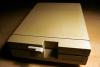
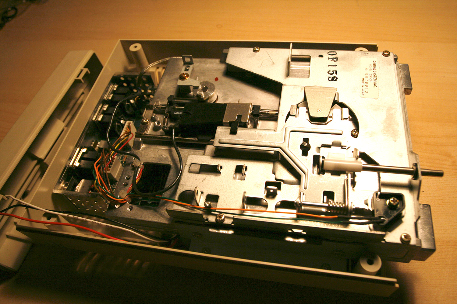
* Every good journey should begin with massacre :-). Grab a malfunctioning 1541 disk drive in good physical shape (photo 1).
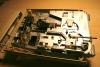
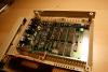
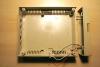
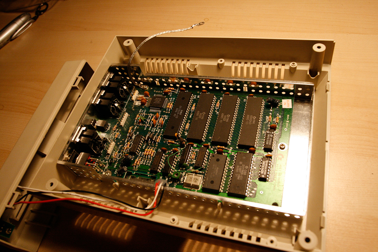
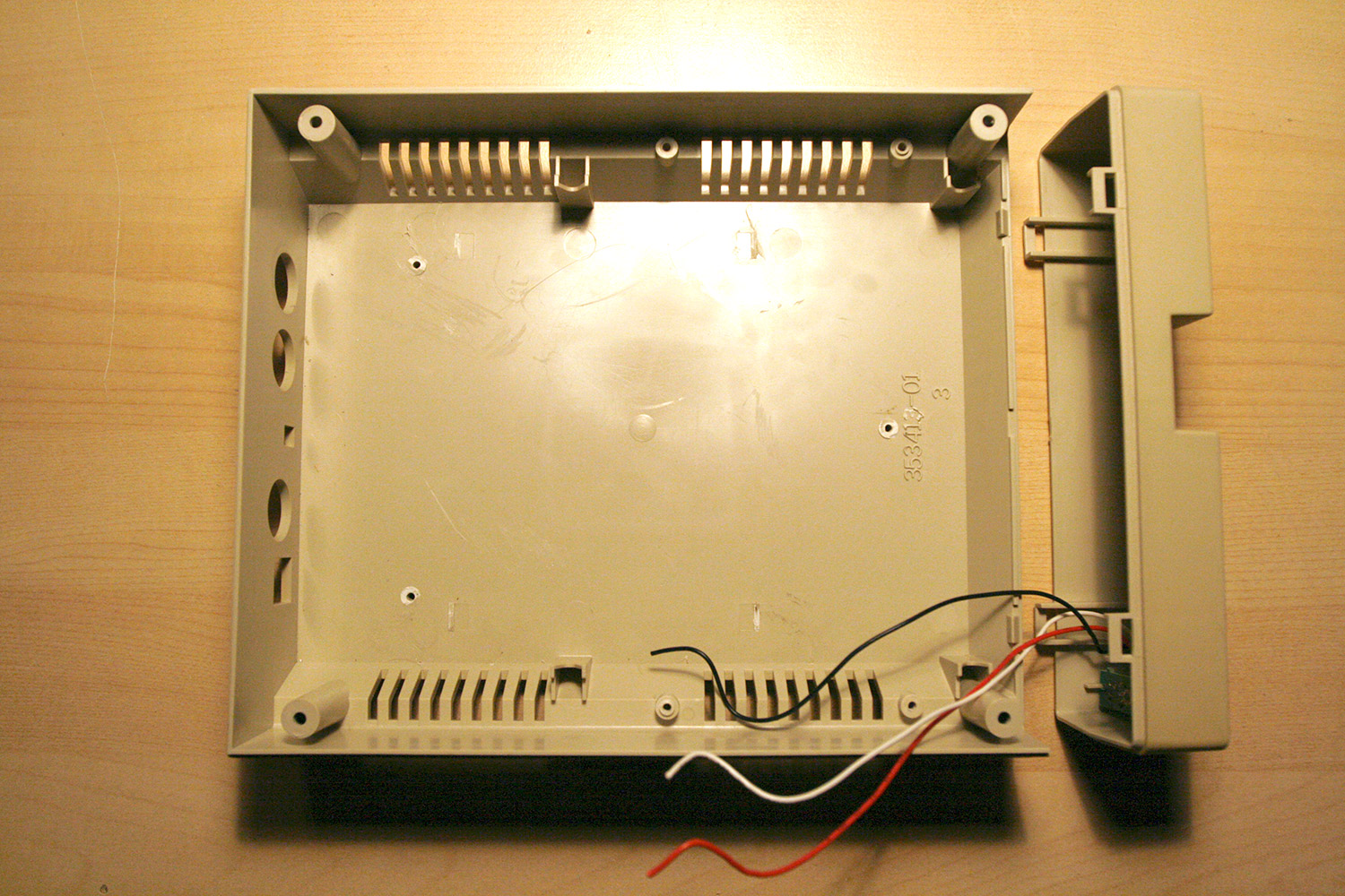
* Disassemble (photos 2 to 4)
* Use the cutter knife to cut away any inner plastic spacers used to hold the 1541 mainboard (photo 4).
* Grab the 1541 PCB and desolder the right serial port and the power switch.
* Do not throw away the 1541 PCB yet, we will need it it the next step.
* Have a cool beverage and enjoy the carnage :-).
-
Hola,
after getting infected with the MB spirit, it is time for another realtime photo-documented feed of a new project, this time a custom MIDIbox SEQ V4 :-).
The last photo tutorial (MB-6582 Control Surface with partslist is available (and still waits for a move to the SID section by nILS :-))).
This MB SEQ variant will include a lot of custom tinkering and therefore has much more room for mistakes and utter failure. If this happens, I expect compassion and tears from you, fellow MBers ^^.
What to expect? We will build a MB SEQ Core in-a-box (retrofitted to a Commodore 1541-II case), a breakout-box Control Surface in a slim, thin and wide aluminium box which can be mounted directly below your master keyboard to minimize hand movements when switching between sequencer and keyboard action. Aiming for VFDs, an integrated AOUT-NG module for Control-Voltage output, duo-color flat-head rectangular step LEDs, a drilled LED matrix bpm indicator, nice Wilba-CS-style keycaps and switches, push-accelerated step encoders and an external BLM. Every step will be photo-documented. I will provide a full parts list and links to parts sellers, where possible.
People interested in building a SEQ from this tutorial may need to adapt a few things... they may not want to use the VFDs or the commodore floppy case for the base unit, but these parts can be substituted. For anyone interested in building a SEQV4 more quickly, I would totally recommend using Wilbas PCB - it is straightforward and saves time and money. In other words: only use this approach if you have space constraints and like the idea of a slim breakout-box CS or wish for a personal customized control surface layout.
Thanks to everyone who made this possible, of course especially TK. and Wilba, who have done a terrific job in realizing wishes, adding requested features to the MBSeq-Software within a week, sending out tech documentation within less than an hour and answering dumb questions... the support here is more awesome than Chuck Norris doing push-ups :-). Also thanks to SmashTV for providing parts in fantastic quality and Seppoman for the AOUT_NG module. Ah, and not to forget nILS ... :-).
As usual, I am interested in your comments on the way - note though, that they might get deleted afterwards, if this project turns out to be working in the end :-).
Lets go and have fun!
Hawkeye
-
nice find, the prices are very good!
-
thanks, seppoman, will keep you posted. as a sidenode, it is incredible how nice they look, in my opinion, they offer a lot more visual eyecandy than common lcds...
-
I googled and identified the lower right one as the AS-4oh4 prototype version with zero polyphony ambience. and i said hit the head, not the foot :)
-
my brain processed that matter in a low priority background task for the last days... and my first outrage has been quite shifted...
the point is, that we will never be able to control what is being sold on a private basis between the people out there... we may be angry and blame profitmakers, but it will be incredibly hard to stop them. and legal effort is never nice effort.
heck... I guess it would even be quite difficult to shut down a chinese (no offense intended) manufacturer cloning TKs and Wilbas code and designs...
-
Ok, i really do not want to be in conflict with you guys, you have given me too much ;-). Just removed the youtube comment... but in my opinion this deal is bad and we need :super: to clean the world from evil :)
-
Wilba, wtf, why do you protect this guy - he charges more than double than its worth - in my eyes that is commercial intent, TK. wrote in the rules that he will deny overpriced sale requests and if this not overpriced, i don´t know what...
-
thx for the comment!
if it does not start burning on me it shall be hacked if necessary :sorcerer:
it does look awesome even when turned off... retro :hairy:
-
couldnt resist posting on youtube - mb the seller does not even know the intellectual property status...
-
update: ordered them yesterday evening via mercateo, they said 16 days delivery time and they arrived this afternoon *coming from the uk*!
Time machine madness! :geek:
Will report on the compatibility with the core32 soon...
-
thiz suckz
-
looks very nice! day of the tentacle rulez ;-). btw. you can get black allen counter sunk screws for the four corners cheaply from ebay for a few euros...
-
the whole album "groove control" rocks! thanks for bumping it, san4os. best regards!
-
fair enough, they will have to suffice then.
Thanks, man!
-
kthxbai :)
edit: within an hour Wilba sent me the scheme... better than sliced bread :), thx!
-
... considering a standard DIN module uses 4x74HC165 and provides "only" 32 ins (but ~90 are required)
... and a standard DOUT module uses 4x74HC595 and provides "only" 32 outs (but ~60 are required)
The pdfs on ucapps.de gave me no clues, as "only" the standard pinning is mentioned, which is fine, but how would i realize dual color step leds for example?
I guess the keywords are "button matrix" and "led matrix", pointers are very welcome...
I found the respective matrix configurations in the wilba/mbseq_hw.v4 file, but don´t understand the associated necessary wiring yet...
thank you very, very much!
Peter
-
Hola, sorry for asking many questions... will try to return the favor with a seq v4 construction photo tutorial :)
Is there ever going to be a chance to use more midi ins than the available two ins from the Core32? I ask, because I think it would be more than nice to have them - would not need to use an external MIDI merger which introduces latency... and existing users could just fully populate their IIC_MIDI modules...
Question to TK. - is it "just" coding effort or is it technically impossible to use the additional four MIDI in ports of the up-to-four IIC_MIDI modules (just merging all inbound data by default would be totally fine).
Thx a lot!
-
good luck on your journey, should you ever want to wander back to explored territory, you can have a look at this cs building photo tutorial, which also contains a full parts list and links to part sellers:
-
The "modulation matrix" chapter for the lead engine describes how each of the eight modulation paths can be configured (e.g. by multiplying two lfos).
After you have a mod path set up, you can assign that path (which basically describes a modulation "waveform" over time) to pitch and pulse width of the three SID voices for each sid pair and filter and volume for each sid pair.
Example: when a LED is lit in column 1 (Mod 1) and row 1 (Pitch of Voice 1) it basically says that the pitches of voice 1 of the stereo sid pair are modulated over time by the modulation path 1 which you have configured.
Regarding the strange button behaviour, a greater mind is required to answer that question :-)
-
hb to nILS!
-
man, you are great *very happy*! looking forward to handing you over some beers in munich :-)
-
you can check the proper wiring of the matrix buttons by just pressing any horizontal matrix button (pitch, pulse width, filter, volume) -> a horizontal line should appear and by pressing any vertical button (modulation sources 1-8) -> a vertical line should appear. It should only switch to meter mode and back when you press the "mode" button left to the matrix. I would suggest taking it apart one more time and looking for accidential solder bridges, first visually, then tracing with a beeper. TK´s fine mbsid v2 handbook on ucapps.de should contain examples for using the matrix.
-
the vfds look great! thank you for the massive heatsink tip and good day to you as well, sir :)

MIDIbox SEQ V4 - Construction Photo Tutorial
in MIDIbox SEQ
Posted · Edited by Hawkeye
Step 2: Prepare the Power Supply Unit
Parts used:
* 5V/+12V/-12V open frame PSU (should have 2A on the +5V chain) (Reichelt PSA 25L-301)
* PSU plug kit (Reichelt PSA 60-STECKER)
* A sufficiently sized plastic or aluminum case (Reichelt TEKO WALL 2 or bigger)
* A rubber connector (german: Kaltgerätestecker Reichelt KES 1)
* 10 pcs M3 12mm screws (any mechanical store or Reichelt)
* 10 pcs M3 nut (any mechanical store or Reichelt)
* 4 pcs M3 nylon washer (any mechanical store or Mouser)
* Commodore 1541 PCB from step 1
* Commodore 1541 serial/data cable
* A bench drill or a hand drill with a 2mm and a 3mm drill
* A few centimeters of cable
* Electric isolation tape
* A 3mm LED and a 220 ohm resistor
* A drop of superglue
* A dremel tool with a cutting wheel
* Your favorite soldering equipment
Description:
We need proper power for the VFDs, and we also want to use the AOUT_NG module, which needs a bipolar power supply (-12V/0V/-12V), that´s why we use an open frame PSU kit commercially available.
* Trim the PSU case, so that the rubber connector and the open frame PSU fit (photo 1).
* Cut a piece of the 1541 PCB (photo 2) containing the left serial port connector, so that it fits neatly into the case (photo 3). Don´t forget to cut the surface connections with your dremel tool (photo 4).
* Solder six power connection wires to the backside of the piece of the 1541 PCB (photo 5). Don´t mind the alignment, we will measure the voltages later on.
* Drill the piece of the 1541 PCB and the bottom of the case. Fasten the serial port connector PCB with M3 screws and nuts (photo 6). Mark the area, where we will plug the serial cable (used as power cable) and cut it, so that you can plug in the cable.
* Install the open frame PSU using the same method (drill the floor of the case and insert M3 screws, use nylon washers as spacers and fasten with M3 nuts (photo 7).
* Crimp and solder the AC mains connector cable and connect to the PSU. Fasten the rubber connector using M3 screws and nuts (photo 8).
* Create the power connector by crimping the six power connection cables. Add a small cable for the power LED to a +5V and a GND line (note: if you measure using your multimeter with power on, take security precautions, as there is dangerous voltage nearby).
* Solder a 220 ohms resistor and a 3mm LED to the end of the cable and isolate with electric tape (photo 9).
* You should drill the case for better air ventilation. You can use graph paper and a 2mm and a 3mm drill (photo 10) to create a matrix of holes. Also create a 3mm hole for the power LED.
* Fasten the LED using a drop of superglue.
* Enjoy your new PSU, it should look like photo 11. All voltages should be available on the serial connector cable, which we will use to power the Core32.