John E. Finster
-
Posts
279 -
Joined
-
Last visited
-
Days Won
7
Content Type
Profiles
Forums
Blogs
Gallery
Everything posted by John E. Finster
-
Hallo nochmal, Ich möchte aber nochmal hier nachhaken. Dass dies eine Schularbeit ist, stand nicht in deiner PM, daher würde mich das schon interessieren. Wie lange hast Du für diese Schularbeit Zeit? Welche Schule und welche Stufe (Klasse)? Hast Du Dir überlegt, wie das finanziert werden kann? Hast Du Lehrer/Mitschüler, die Dir helfen können? Sorry für die vielen Fragen, aber ich denke, das sollte mal geklärt werden. Gruß
-
Hey, it just hit me . Since what you want to acchieve isn´t technically the same you asked for in the initial topic (sending different CCs by pressing/depressing a button) you could try something more simple. Now you want to send 2 CCs by pressing a button and the same 2 CCs by depressing, just with a different value. So I think something like this could work: In the *.NGC file assign 2 events to one button with a specific range and button mode: With that button mode and range the button (solo track 1) sends CC15 0 + CC47 67 when pressed and CC15 0 + CC47 3 when depressed. If this works you wouldn´t need a *.NGR script and you could assign all the button within the *.NGC file. I can´t guarantee for that though. Like I said, I won´t be home till next week to test this for myself. my regards
-
Hi, you can create as many sections in the *.NGR as you like. Here are some examples for the solo/mute/rec buttons of track 1 The according BUTTON events in the *.NGC file would be: Of course you have to keep track of all the button ids and the according section numbers. my regards
-
Hallo und willkommen, wollen wir mal schauen.... 8x8 Matrix --> da sind DIO_Matrix Module besser, die haben bereits 2 DIN und 2 DOUT Register für 2 8x8 Matrizen 128 Dehregler --> Endlosregler? Wenn ja, dann brauchst Du 8 DINx4 Module (1 DINx4 = 16 Endlosregler) --> Potis ? Dann brauchst Du 2 AINSER64 Module, da Potis analog sind. Fader --> Für 8 Fader brauchst Du ein AINSER8 Modul, bzw, für mehr dann das AINSER64 Modul. --> Falls es Motorfader sein sollen, dann brauchst Du für 8 Motorfader ein MF_NG Modul XY Controller --> kann ich nichts zu sagen, habe ich noch nie benutzt. Ansonsten natürlich ein LPC17 Modul, wobei Du das LPCXPRESSO Board, das auf das Modul draufkommt, nicht bei SmashTV bekommst. SD Karte brauchst Du natürlich auch, einen passenden Anschluss kannst DU Dir einfach selbst basteln. Liebe Grüße und viel Spaß :happy: John
-
Unfortunatly I´m not able to test this atm. I´m far away from home (and from my midiboxes :bye: ) for a few days. Next week I will be able to test this. I suggest you try and put something like this in the *.NGR: This is for the Solo on Track 1. For the other tracks the cc15 value has to be changed from 0-7.
-
Ok, I found my old notes from my "Motormix Studies" with cubase I did a few years ago and I think I can dare to take a shot at this: For every button there has to be sent 2 CCs, the first one selects the channel and the second one sets the function (like solo, mute,.....). Now, if I remember correctly, the 2 CCs have to be sent twice (so 4 events in total) with different values to set a function. Regarding the PING, I think you can ignore it for now. The Mackie Protocol too has some kind of PING thingie integrated but I didn´t have any trouble ignoring it (at least with Reaper and Ableton). EDIT: Sorry, I got some messed up notes lying here :rofl: . I changed the events again...
-
With what DAW are you trying to use the motormix emulation? I remember that cubase sends different midi events to the motormix than described in the motormix manual.
-
Hi Reggie, I didn´t follow the developement of the stm32f4 discovery closely, but I don´t think it is quite ready yet to be integrated into the midibox hardware platform and probably won´t be until some time next year. So If you want to start now and don´t want to wait a year, you could focus on the current LPC17 core. As far as I see it, every idea you have about your controller can be easily realised by the available technology right now. I suggest you have a look into the MB_NG firmware here, which is the most flexibel and powerful one right now. Also have a look at all the available hardware modules. I think you misunderstood the concept behind them. First you need a core module (like the LPC17) that is able to run the MIOS32 system and the firmware you like. If you want to use hardware elements like buttons/encoders/leds/.... you have to connect all that to the core via another hardware module, the core itself doesn´t provide (many) pins for direct connections and neither will the new stm32f4 core. So you need additional modules for your control surface elements: encoders, buttons ----> DIN module faders, pots ----> AIN or AINSER module motorfader ----> MF_NG module leds ----> DOUT module etc........ Have fun! my regards
-
Hi, I´m not able to test it for myself atm, but maybe this could do it. I´m using similar methods for my own box. You need a *.NGR script to do that: in the *.NGC: and in the *.NGR: Maybe this will do the trick. my regards EDIT: Just tested it and it works! The button sends CC15 v0 when pressing and CC47 v67 when depressing.
-

Finished MB_NG / Mackie Control Clone
John E. Finster replied to John E. Finster's topic in MIDIbox NG
Hi KUI, a schematic for one shift register can be found here. You could also use a regular DOUT module. Actually I recommend using a full DOUT module (4 shift registers). Because of a problem with my ssd1306 displays I was forced to skip every second shift register pin, so I have only 4 displays per shift register. I had some more trouble (well, still having...) with the displays. If you are interested, you can read about it in I was able to solve some of the problems myself, but there is still one open issue. I hope this can be resolved soon. my regards -
Poll: RAM consumption of your .NGC configurations
John E. Finster replied to TK.'s topic in MIDIbox NG
MB_NG V1.027 Event Pool Number of Items: 201 Event Pool Allocation: 7329 of 24576 bytes (29%) Every label is stored in the *.NGL file. Only a few are defined in the *.NGC (direct ´LCD "" ´ messages plus some sysex messages). That´s without any banks for now. I´m planing on using at least one other bank and probably lots of conditional events in the future. -
Analog scanning of manuals: Is it fast enough?
John E. Finster replied to Sander's topic in MIDIfication
Hi, to make use of the new MIOS32 you have to get a new LPC17 core module. my regards -
Mackie Control Clone by John E. Finster 1
John E. Finster commented on John E. Finster's gallery image in Members Gallery
 Thanks for the compliments. I uploaded more pics on my wiki site here, in case someone is interested.
 -
Finished MB_NG / Mackie Control Clone
John E. Finster replied to John E. Finster's topic in MIDIbox NG
small update: more pics are available on my wiki site now here. -
Finished MB_NG / Mackie Control Clone
John E. Finster replied to John E. Finster's topic in MIDIbox NG
I got them on ebay from a chinese dealer for ~ 9$ a piece plus gratis shipment. my regards -
Finished MB_NG / Mackie Control Clone
John E. Finster replied to John E. Finster's topic in MIDIbox NG
Hi, Thanks for the compliment. Well, regarding the time... With all the "normal" everyday background (familiy, job,...), once I had all the parts, it took me about 4 weeks to put it together, another 2 months to fight bugs and mistakes I built in (I was a little too eager and impatient at the start...) and maybe another 2 months to create the necessary scripts (.ngc, .ngl and .ngr) and fonts/icons to get it to work like that. Of course a lot more time went into the research of the Midibox concept, hardware and software knowledge and figuring out what I wanted in the first place. I´ve been around here for the last 6 years, that´s when I started to build my first cardboard midiboxes. I had to get a break when my lovely daughter was born to take care of more important issues, but from time to time I was sneaking away from that to continue my Midibox research. Of course without that much in the background, on top of mine I was a college student until 3 months ago, I would say it doesn´t take more than 6 months to research the Theory and to build some simple boxes to experiment. I think the hardest part in all this is to get started.... my regards -
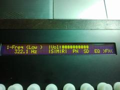
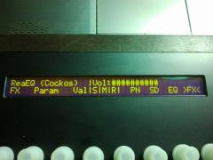
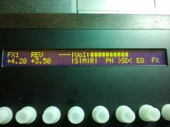
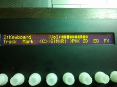
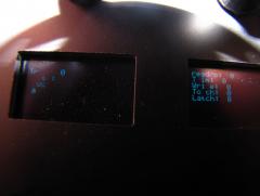
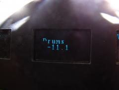
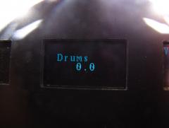
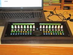
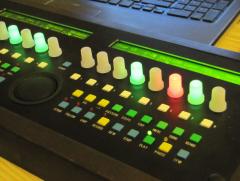
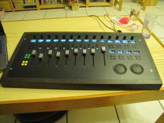
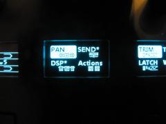
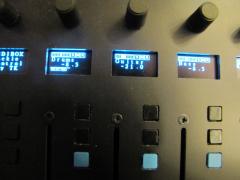
Hi, I´d like to present my newest built. Today I finished a preliminary *.NGC file to get it to work like I want it to, so I´m officially announcing it finished :sorcerer: . This is supposed to act as a Mackie Control Clone, but I tried to keep the designation of the design as wide open as possible to use it for other purposes as well. There are still some issues I have to work out (mostly related to the SSD1306 displays), but as for now it´s usable as it is. Here you go: It features: 9 Penny&Giles motorfaders (8 track faders + 1 master fader) 14 Encoders 2 jog dials with different caps (one with pimples and one with a finger hole) 70 multi-purpose buttons 18 SSD1306 displays customised fonts and icons Inside are: 1 LPC17 core 2 MF_NG modules 1 DOUT module 4 DIN modules This Midibox is powered by a simple Wall adapter with 14V 2A. I didn´t print any labels onto the front panel. There are some color-coded buttons for the most needed functions (track select + shift and modifier buttons). The purpose of all other buttons can be indicated by a label printed on one of the SSD1306 displays. This ensures that I can change the function (and the apropriate label) of almost every button without worrying about any labels/indication leds/front panel positions. The frontpanel is made by Schaeffer, the case is made out of beech tree. I will provide a more detailed documentation in the wiki soon. Many thanks to TK and to the very helpful community, without which I would have never come this far. my regards
-
-
-
From the album: [John E. Finster] pics and such
-
From the album: [John E. Finster] pics and such
-
From the album: [John E. Finster] pics and such
-
Hi, do you want to connect this USB-powered keyboard controller to the MIDIO128 directly, so that midi data can go from the keyboard to the MIDIO128? In this case, you have to use the midi in/out connections of the core, this can not be achieved by an USB connection. Also the USB plug of the MIDIO128 does not deliver currency, when it is powered by an external psu. How would your setup look like? 1. MIDIO128 -> PC/Mac and keyboard -> PC/Mac for this scenario I would recommend an active usb hub, where you can connect both the MIDIO128 and the USB-powered keyboard controller. But here no direct connection is possible, everything has to go through the computer. 2. Keyboard -> MIDIO128 -> PC/Mac the keyboard here has to be connected via midi in/out, the USB connection can not be shared. 3. Keyboard -> MIDIO128 -> Synths/other Midi gear the keyboard here also has to be connected via midi in/out, the USB plug does not deliver currency. It is possible to build in a seperate plug for 5V that matches the USB cabel. It could be connected to an open 5V line on the inside. But it would not be possible to send/receive midi data over the usb connection anymore.
-
LED VU Meters, Encoders and SSD1306 Displays
John E. Finster replied to ibanman555's topic in MIDIbox NG
Yeah, it´s kinda interesting. I had to look twice a the midi input monitor of Mios Studio to get it :happy: . If you choose Motormix emulation and look at the direct output of the MF module in Mios Studio you can see two CCs instead of one when you move a fader. So that´s how 14bit resolution is generated. (CC a) x (CC b) = 128 x 128 = 16384 = 14bit! With the regular pitchbend mode or the mackie/logic emulation mode there would only be a 10bit resolution available. -
LED VU Meters, Encoders and SSD1306 Displays
John E. Finster replied to ibanman555's topic in MIDIbox NG
If you want to use a mackie/logic emulation, you´re right. For other applications you could use other modes. I believe it has something to do with the resolution of the faders. The Motormix mode provides 14bit fader resolution. my regards -
LED VU Meters, Encoders and SSD1306 Displays
John E. Finster replied to ibanman555's topic in MIDIbox NG
Ahh, I see light.... :w00t: . (sorry, I had to put my grammy into a hospital last night..........again.......... so I´m a bit exhausted. Ok, back to topic!) I don´t know about the command8, but the others, HUI and Motormix, are documented. With HUI you might be able to set up....: - vu-meters -> transported by a key aftertouch event which could be recognized by a MB_NG and translated into a led or lcd event. - encoders, switches, led-rings -> they´re all continous controller events which can be assigned by MB_NG - 2x40 lcd display -> for displaying fx parameters (like HUI), sent within a sysex stream which could also be recognized by MB_NG and displayed on a lcd. With Motormix you might be able to set up....: - 2x40 lcd display -> track names, also sent within a sysex stream. - encoders, switches, led-rings -> like HUI You could combine both protocols into one "midibox bar" to attach to your fader boxes. HUI could give you metering and Motormix could give you LCDs with track names,... I recommend you monitor the midi output of all 3 midi protocols (from command8, too) to see, what and how controller information is transported (this can differ from daw to daw). You already know Midiox, which is an excellent tool for that. Just connect the midi out of protools midi protocols to midiox (via LoopBe or other virtual midi cable) and record the output. If everything is alright you should able to see note/controller/aftertouch/sysex commands from protools, which we can interpret and maybe emulate. A word of caution to this tale...(my kid loves that disney Hercules movie...) 1. Everything I wrote here is considered hypothetical. I got similar stuff to work with my boxes, but of course I can not guarantee that any of this will work in your case. Especially, since I don´t know Protools and its potentials. 2. Since you´re focused on meters I´d like to add another comment. Midi-driven meters are never that accurate as audio-driven meters or those you see on the screen of your laptop/pc/mac...whatever. They can be (rough) indicators of what is going on, the whole meter length is roughly divided into 11-13 sections and they have a noticeable latency. If you´re looking for professional and precise meters, a midicontroller is might not be the solution. Then again, I am really tired right now, so if any of what I just wrote doesn´t make any sense, please bear with me :ahappy: . my regards P.S.: If you can give me some time, I could test the metering feature of the HUI protocol within Reaper (IF it supports metering) and report back.