ksir
-
Posts
97 -
Joined
-
Last visited
-
Days Won
6
Content Type
Profiles
Forums
Blogs
Gallery
Everything posted by ksir
-
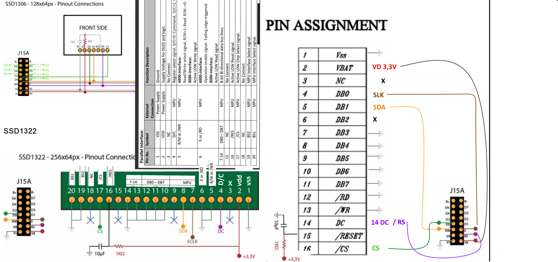
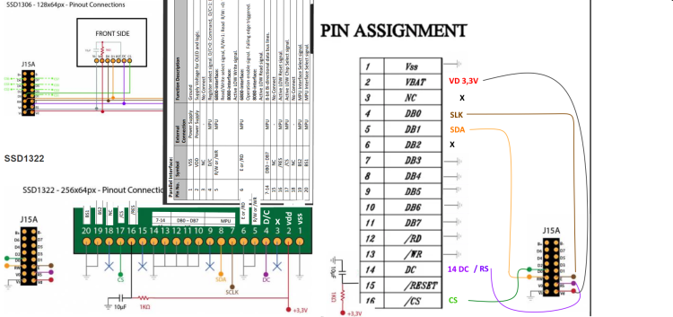
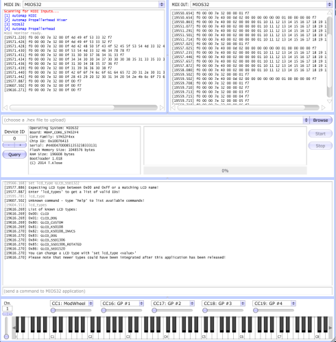
THANKS . I don't understand the interconnection diagram clearly. My screen has 16 pins not 20 pins and the name of the pins on the seller's diagram does not correspond. hence my confusion ( https://fr.aliexpress.com/item/32414142892.html?gatewayAdapt=glo2fra ) I just tried to match : it's ok ? i can't fide GLCD_SSD1322
-
Hello, I have a tw56640320b03 screen, is it possible to make it work with midibox ng? THANKS https://s.alicdn.com/@sc01/kf/HTB19t6LcXkoBKNjSZFkq6z4tFXa3/232025343/HTB19t6LcXkoBKNjSZFkq6z4tFXa3.jpg
-
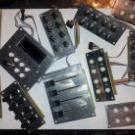
[S] 7x MB-LRE8x2 CS Rev 2.5 (fully stuffed with parts)
ksir replied to Phatline's topic in Fleamarket
I am interested in the 2 white ones with push button -
thank you for your help I tried : #PADS EVENT_BUTTON id= 65 hw_id= 33 fwd_id=RGBLED:137 type=CC chn= 1 cc= 33 button_mode= Toggle label= "^std_btn" bank= 1 hsv= 50:100:10 debounce_cycles=65535 EVENT_BUTTON id= 66 hw_id= 35 fwd_id=RGBLED:138 type=CC chn= 1 cc= 34 button_mode= Toggle label= "^std_btn" bank= 1 hsv= 100:100:10 debounce_cycles=65535 EVENT_BUTTON id= 67 hw_id= 37 fwd_id=RGBLED:139 type=CC chn= 1 cc= 35 button_mode= Toggle label= "^std_btn" bank= 1 hsv= 0:100:10 debounce_cycles=65535 EVENT_BUTTON id= 68 hw_id= 39 fwd_id=RGBLED:140 type=CC chn= 1 cc= 36 button_mode= Toggle label= "^std_btn" bank= 1 hsv= 200:100:10 debounce_cycles=65535 EVENT_BUTTON id= 69 hw_id= 34 fwd_id=RGBLED:141 type=CC chn= 1 cc= 37 button_mode= Toggle label= "^std_btn" bank= 1 hsv= 50:100:10 debounce_cycles=65535 EVENT_BUTTON id= 70 hw_id= 36 fwd_id=RGBLED:142 type=CC chn= 1 cc= 38 button_mode= Toggle label= "^std_btn" bank= 1 hsv= 100:100:10 debounce_cycles=65535 EVENT_BUTTON id= 71 hw_id= 38 fwd_id=RGBLED:143 type=CC chn= 1 cc= 39 button_mode= Toggle label= "^std_btn" bank= 1 hsv= 0:100:10 debounce_cycles=65535 EVENT_BUTTON id= 72 hw_id= 40 fwd_id=RGBLED:144 type=CC chn= 1 cc= 40 button_mode= Toggle label= "^std_btn" bank= 1 hsv= 200:100:10 debounce_cycles=65535 #PADS EVENT_BUTTON id= 73 hw_id= 41 fwd_id=RGBLED:129 type=CC chn= 1 cc= 41 button_mode= Toggle label= "^std_btn" bank= 1 hsv= 50:100:10 debounce_cycles=65535 EVENT_BUTTON id= 74 hw_id= 43 fwd_id=RGBLED:130 type=CC chn= 1 cc= 42 button_mode= Toggle label= "^std_btn" bank= 1 hsv= 100:100:10 debounce_cycles=65535 EVENT_BUTTON id= 75 hw_id= 45 fwd_id=RGBLED:131 type=CC chn= 1 cc= 43 button_mode= Toggle label= "^std_btn" bank= 1 hsv= 0:100:10 debounce_cycles=65535 EVENT_BUTTON id= 76 hw_id= 47 fwd_id=RGBLED:132 type=CC chn= 1 cc= 44 button_mode= Toggle label= "^std_btn" bank= 1 hsv= 200:100:10 debounce_cycles=65535 EVENT_BUTTON id= 77 hw_id= 42 fwd_id=RGBLED:133 type=CC chn= 1 cc= 45 button_mode= Toggle label= "^std_btn" bank= 1 hsv= 50:100:10 debounce_cycles=65535 EVENT_BUTTON id= 78 hw_id= 44 fwd_id=RGBLED:134 type=CC chn= 1 cc= 46 button_mode= Toggle label= "^std_btn" bank= 1 hsv= 100:100:10 debounce_cycles=65535 EVENT_BUTTON id= 79 hw_id= 46 fwd_id=RGBLED:135 type=CC chn= 1 cc= 47 button_mode= Toggle label= "^std_btn" bank= 1 hsv= 0:100:10 debounce_cycles=65535 EVENT_BUTTON id= 80 hw_id= 48 fwd_id=RGBLED:136 type=CC chn= 1 cc= 48 button_mode= Toggle label= "^std_btn" bank= 1 hsv= 200:100:10 debounce_cycles=65535 doesn't seem to work
-
Hello, I haven't studied your answer in depth yet, but here is an example of declaration of my pads in ngc file #PADS EVENT_BUTTON id= 33 fwd_id=RGBLED:137 hsv=50:100:10 type=CC chn= 1 cc= 33 button_mode=Toggle label="^std_btn" EVENT_BUTTON id= 35 fwd_id=RGBLED:138 hsv=100:100:10 type=CC chn= 1 cc= 35 button_mode=Toggle label="^std_btn"
-
Hello, I have a rebound problem with the sparkfun pads, do you have an idea how to fix this? Hardware? Software ? Thanks The rest works fine

-
yes all encoders work, after having pushed the tests a little, I have the impression that it is the accent (é) in the comments of my code which poses a problem and erases lines at the end of my ngc file
-
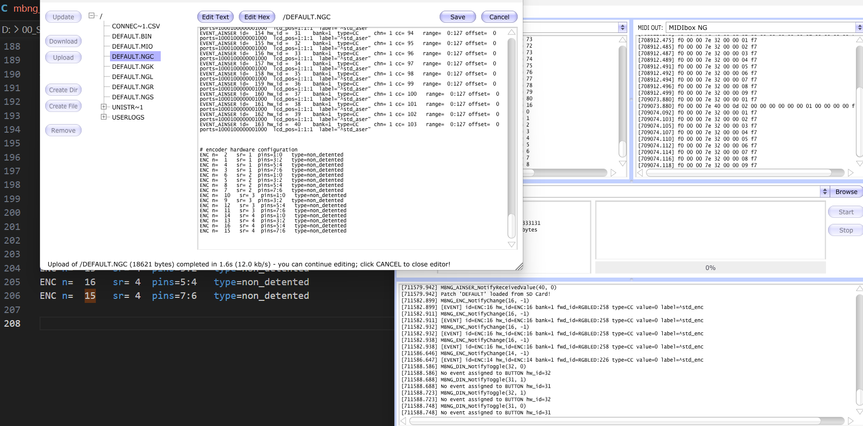
Thank you again for your help I tried : # encode hardware configuration ENC n= 16 sr= 4 pins=5:4 type=non_detented ENC n= 15 sr= 4 pins=7:6 type=non_detented ENC n= 2 sr= 1 pins=1:0 type=non_detented ENC n= 1 sr= 1 pins=3:2 type=non_detented ENC n= 4 sr= 1 pins=5:4 type=non_detented ENC n= 3 sr= 1 pins=7:6 type=non_detented ENC n= 6 sr= 2 pins=1:0 type=non_detented ENC n= 5 sr= 2 pins=3:2 type=non_detented ENC n= 8 sr= 2 pins=5:4 type=non_detented ENC n= 7 sr= 2 pins=7:6 type=non_detented ENC n= 10 sr= 3 pins=1:0 type=non_detented ENC n= 9 sr= 3 pins=3:2 type=non_detented ENC n= 12 sr= 3 pins=5:4 type=non_detented ENC n= 11 sr= 3 pins=7:6 type=non_detented ENC n= 14 sr= 4 pins=1:0 type=non_detented ENC n= 13 sr= 4 pins=3:2 type=non_detented It's encoder 13 that didn't work anymore I moved the encoder hardware config code to the middle of the code, instead of putting it at the end, now it works
-
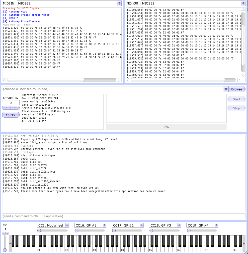
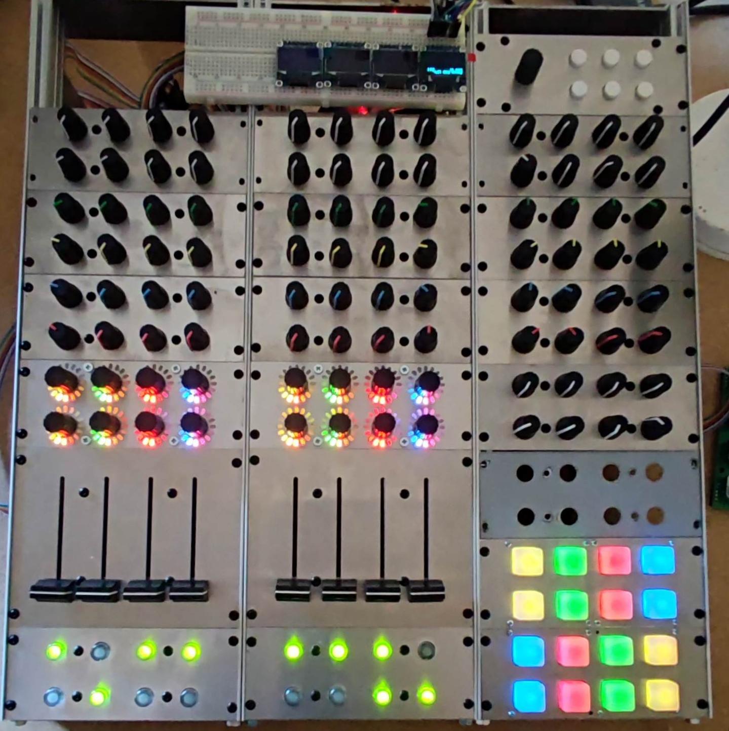
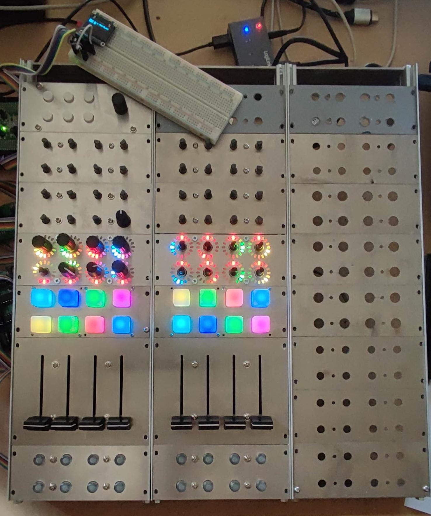
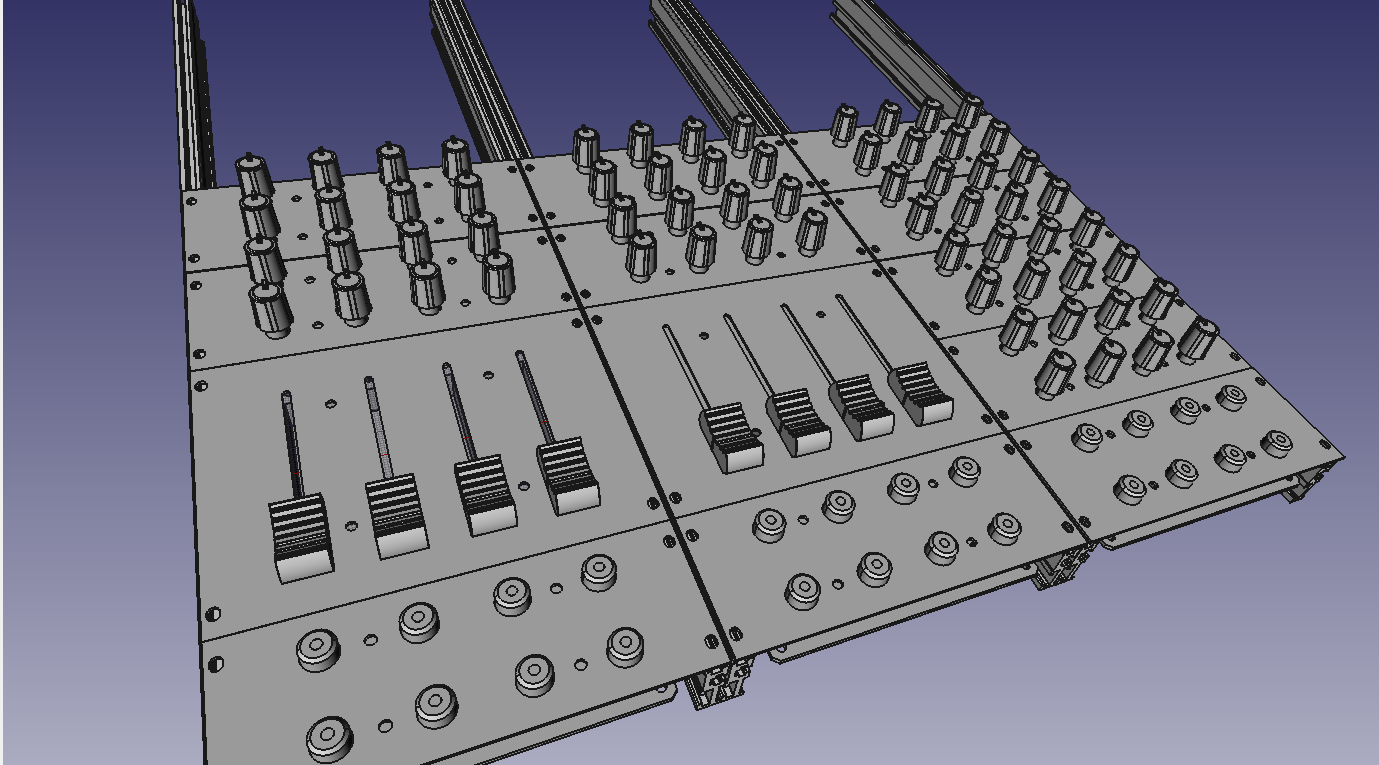
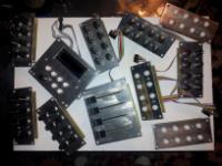
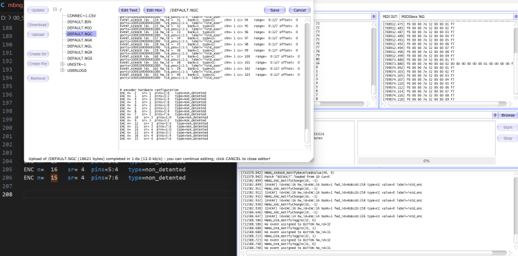
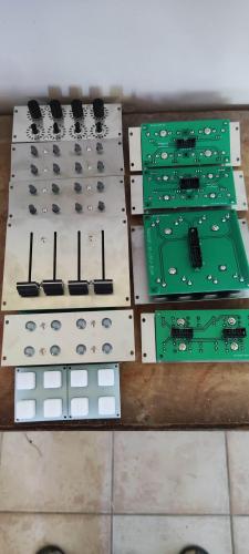
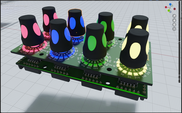
Unable to operate encoder #15 he is detected by mios studio but he answers me: not event assigned, yet I seem to have configured it like the other 15 which works well... Thanks for your help #Modulbox RESET_HW # le SCS doit émuler les fonctions bouton/enc dans la page principale SCS soft1_button_emu_id=2000 \ soft2_button_emu_id=2001 \ soft3_button_emu_id=2002 \ soft4_button_emu_id=2003 \ shift_button_emu_id=2004 \ enc_emu_id=2000 # Contrôlé à partir des boutons SCS à J10 dans la page principale EVENT_BUTTON id=2000 type=Meta meta=SetBank button_mode=OnOnly range=1:1 lcd_pos=1:17:2 label="Bnk%q" EVENT_BUTTON id=2001 type=Meta meta=SetBank button_mode=OnOnly range=2:2 lcd_pos=1:17:2 label="Bnk%q" EVENT_BUTTON id=2002 type=Meta meta=SetBank button_mode=OnOnly range=3:3 lcd_pos=1:17:2 label="Bnk%q" EVENT_BUTTON id=2003 type=Meta meta=SetBank button_mode=OnOnly range=4:4 lcd_pos=1:17:2 label="Bnk%q" EVENT_BUTTON id=2004 type=Meta meta=EncFast:4 button_mode=OnOff range=2:0 # l'encodeur SCS en J10 incrémente/décrémente simplement la banque # fonction redondante - pourrait être modifiée à l'avenir EVENT_ENC id=2000 type=Meta meta=SetBank range=1:4 # le but de cet élément EVENT est d'imprimer la banque chaque fois que l'écran LCD est rafraîchi (par exemple après le démarrage ou le changement de banque) EVENT_LED id=2000 fwd_to_lcd=1 lcd_pos=1:1:2 label="Bank #%q" # ENC 1 - 8 /////////////////////////////////////////////////// # Classical Thermometer Pattern, Jaune #EVENT_ENC id= 1 hw_id = 1 bank=1 fwd_id=RGBLED:2 rgbled_pattern=1 hsv=50:100:10 fwd_to_lcd=1 type=CC chn= 1 cc= 16 range= 0:127 offset= 0 ports=1000100000001000 lcd_pos=1:1:1 # label="ENC #%3i %3d@(1:1:2)%B" # ENC 1 Moving Dot ,jaune EVENT_ENC id= 1 hw_id = 1 bank=1 fwd_id=RGBLED:2 rgbled_pattern=2 hsv=50:100:10 fwd_to_lcd=1 type=CC chn= 1 cc= 1 range= 0:127 offset= 0 ports=1000100000001000 lcd_pos=1:1:1 label="^std_enc" # ENC 2 Moving Dot , Green EVENT_ENC id= 2 hw_id = 2 bank=1 fwd_id=RGBLED:18 rgbled_pattern=2 hsv=100:100:10 fwd_to_lcd=1 type=CC chn= 1 cc= 2 range= 0:127 offset= 0 ports=1000100000001000 lcd_pos=1:1:1 label="^std_enc" # ENC 3 Moving Dot , RED EVENT_ENC id= 3 hw_id = 3 bank=1 fwd_id=RGBLED:34 rgbled_pattern=2 hsv=0:100:10 fwd_to_lcd=1 type=CC chn= 1 cc= 3 range= 0:127 offset= 0 ports=1000100000001000 lcd_pos=1:1:1 label="^std_enc" # ENC 4 Moving Dot , Blue EVENT_ENC id= 4 hw_id = 4 bank=1 fwd_id=RGBLED:50 rgbled_pattern=2 hsv=200:100:10 fwd_to_lcd=1 type=CC chn= 1 cc= 4 range= 0:127 offset= 0 ports=1000100000001000 lcd_pos=1:1:1 label="^std_enc" # ENC 5 Moving Dot Jaune EVENT_ENC id= 5 hw_id = 5 bank=1 fwd_id=RGBLED:66 rgbled_pattern=2 hsv=50:100:10 fwd_to_lcd=1 type=CC chn= 1 cc= 5 range= 0:127 offset= 0 ports=1000100000001000 lcd_pos=1:1:1 label="^std_enc" # ENC 6 Moving Dot GREEN EVENT_ENC id= 6 hw_id = 6 bank=1 fwd_id=RGBLED:82 rgbled_pattern=2 hsv=100:100:10 fwd_to_lcd=1 type=CC chn= 1 cc= 6 range= 0:127 offset= 0 ports=1000100000001000 lcd_pos=1:1:1 label="^std_enc" # ENC 7 Moving Dot RED EVENT_ENC id= 7 hw_id = 7 bank=1 fwd_id=RGBLED:98 rgbled_pattern=2 hsv=0:100:10 fwd_to_lcd=1 type=CC chn= 1 cc= 7 range= 0:127 offset= 0 ports=1000100000001000 lcd_pos=1:1:1 label="^std_enc" # ENC 8 Moving Dot BLUE #label="Enc%3i&k@(1:4:6)%B&n@(1:19:5)%3d" EVENT_ENC id= 8 hw_id = 8 bank=1 fwd_id=RGBLED:114 rgbled_pattern=2 hsv=200:100:10 fwd_to_lcd=1 type=CC chn= 1 cc= 8 range= 0:127 offset= 0 ports=1000100000001000 lcd_pos=1:1:1 label="^std_enc" # ENC 9-16 ///////////////////////////////////////////////////////// # Moving Dot Jaune EVENT_ENC id= 9 hw_id = 9 bank=1 fwd_id=RGBLED:146 rgbled_pattern=2 hsv=50:100:10 fwd_to_lcd=1 type=CC chn= 1 cc= 9 range= 0:127 offset= 0 ports=1000100000001000 lcd_pos=1:1:1 label="^std_enc" # Moving Dot GREEN EVENT_ENC id= 10 hw_id = 10 bank=1 fwd_id=RGBLED:162 rgbled_pattern=2 hsv=100:100:10 fwd_to_lcd=1 type=CC chn= 1 cc= 10 range= 0:127 offset= 0 ports=1000100000001000 lcd_pos=1:1:1 label="^std_enc" # Moving Dot RED EVENT_ENC id= 11 hw_id = 11 bank=1 fwd_id=RGBLED:178 rgbled_pattern=2 hsv=0:100:10 fwd_to_lcd=1 type=CC chn= 1 cc= 11 range= 0:127 offset= 0 ports=1000100000001000 lcd_pos=1:1:1 label="^std_enc" # Moving Dot BLUE EVENT_ENC id= 12 hw_id = 12 bank=1 fwd_id=RGBLED:194 rgbled_pattern=2 hsv=200:100:10 fwd_to_lcd=1 type=CC chn= 1 cc= 12 range= 0:127 offset= 0 ports=1000100000001000 lcd_pos=1:1:1 label="^std_enc" # Moving Dot Jaune EVENT_ENC id= 13 hw_id = 13 bank=1 fwd_id=RGBLED:210 rgbled_pattern=2 hsv=50:100:10 fwd_to_lcd=1 type=CC chn= 1 cc= 13 range= 0:127 offset= 0 ports=1000100000001000 lcd_pos=1:1:1 label="^std_enc" # Moving Dot GREEN EVENT_ENC id= 14 hw_id = 14 bank=1 fwd_id=RGBLED:226 rgbled_pattern=2 hsv=100:100:10 fwd_to_lcd=1 type=CC chn= 1 cc= 14 range= 0:127 offset= 0 ports=1000100000001000 lcd_pos=1:1:1 label="^std_enc" # Moving Dot RED EVENT_ENC id= 15 hw_id = 15 bank=1 fwd_id=RGBLED:242 rgbled_pattern=2 hsv=0:100:10 fwd_to_lcd=1 type=CC chn= 1 cc= 15 range= 0:127 offset= 0 ports=1000100000001000 lcd_pos=1:1:1 label="^std_enc" # Moving Dot BLUE EVENT_ENC id= 16 hw_id = 16 bank=1 fwd_id=RGBLED:258 rgbled_pattern=2 hsv=200:100:10 fwd_to_lcd=1 type=CC chn= 1 cc= 16 range= 0:127 offset= 0 ports=1000100000001000 lcd_pos=1:1:1 label="^std_enc" #bouton poussoir encodeurs 1 EVENT_BUTTON id= 66 fwd_id=RGBLED:1 hsv=00:100:10 type=CC chn= 1 cc= 17 button_mode=Toggle label="^std_btn" EVENT_BUTTON id= 65 fwd_id=RGBLED:17 hsv=0:100:10 type=CC chn= 1 cc= 18 button_mode=Toggle label="^std_btn" EVENT_BUTTON id= 68 fwd_id=RGBLED:33 hsv=0:100:10 type=CC chn= 1 cc= 19 button_mode=Toggle label="^std_btn" EVENT_BUTTON id= 67 fwd_id=RGBLED:49 hsv=0:100:10 type=CC chn= 1 cc= 20 button_mode=Toggle label="^std_btn" EVENT_BUTTON id= 70 fwd_id=RGBLED:65 hsv=0:100:10 type=CC chn= 1 cc= 21 button_mode=Toggle label="^std_btn" EVENT_BUTTON id= 69 fwd_id=RGBLED:81 hsv=0:100:10 type=CC chn= 1 cc= 22 button_mode=Toggle label="^std_btn" EVENT_BUTTON id= 72 fwd_id=RGBLED:97 hsv=0:100:10 type=CC chn= 1 cc= 23 button_mode=Toggle label="^std_btn" EVENT_BUTTON id= 71 fwd_id=RGBLED:113 hsv=0:100:10 type=CC chn= 1 cc= 24 button_mode=Toggle label="^std_btn" #bouton poussoir encodeurs 2 EVENT_BUTTON id= 74 fwd_id=RGBLED:145 hsv=00:100:10 type=CC chn= 1 cc= 25 button_mode=Toggle label="^std_btn" EVENT_BUTTON id= 73 fwd_id=RGBLED:161 hsv=0:100:10 type=CC chn= 1 cc= 26 button_mode=Toggle label="^std_btn" EVENT_BUTTON id= 76 fwd_id=RGBLED:177 hsv=0:100:10 type=CC chn= 1 cc= 27 button_mode=Toggle label="^std_btn" EVENT_BUTTON id= 75 fwd_id=RGBLED:193 hsv=0:100:10 type=CC chn= 1 cc= 28 button_mode=Toggle label="^std_btn" EVENT_BUTTON id= 78 fwd_id=RGBLED:209 hsv=0:100:10 type=CC chn= 1 cc= 29 button_mode=Toggle label="^std_btn" EVENT_BUTTON id= 77 fwd_id=RGBLED:225 hsv=0:100:10 type=CC chn= 1 cc= 30 button_mode=Toggle label="^std_btn" EVENT_BUTTON id= 80 fwd_id=RGBLED:241 hsv=0:100:10 type=CC chn= 1 cc= 31 button_mode=Toggle label="^std_btn" EVENT_BUTTON id= 79 fwd_id=RGBLED:257 hsv=0:100:10 type=CC chn= 1 cc= 32 button_mode=Toggle label="^std_btn" #PADS EVENT_BUTTON id= 33 fwd_id=RGBLED:137 hsv=50:100:10 type=CC chn= 1 cc= 33 button_mode=Toggle label="^std_btn" EVENT_BUTTON id= 35 fwd_id=RGBLED:138 hsv=100:100:10 type=CC chn= 1 cc= 35 button_mode=Toggle label="^std_btn" EVENT_BUTTON id= 37 fwd_id=RGBLED:139 hsv=0:100:10 type=CC chn= 1 cc= 37 button_mode=Toggle label="^std_btn" EVENT_BUTTON id= 39 fwd_id=RGBLED:140 hsv=200:100:10 type=CC chn= 1 cc= 39 button_mode=Toggle label="^std_btn" EVENT_BUTTON id= 34 fwd_id=RGBLED:141 hsv=50:100:10 type=CC chn= 1 cc= 34 button_mode=Toggle label="^std_btn" EVENT_BUTTON id= 36 fwd_id=RGBLED:142 hsv=100:100:10 type=CC chn= 1 cc= 36 button_mode=Toggle label="^std_btn" EVENT_BUTTON id= 38 fwd_id=RGBLED:143 hsv=0:100:10 type=CC chn= 1 cc= 38 button_mode=Toggle label="^std_btn" EVENT_BUTTON id= 40 fwd_id=RGBLED:144 hsv=200:100:10 type=CC chn= 1 cc= 40 button_mode=Toggle label="^std_btn" #PADS EVENT_BUTTON id= 41 fwd_id=RGBLED:129 hsv=50:100:10 type=CC chn= 1 cc= 41 button_mode=Toggle label="^std_btn" EVENT_BUTTON id= 43 fwd_id=RGBLED:130 hsv=100:100:10 type=CC chn= 1 cc= 43 button_mode=Toggle label="^std_btn" EVENT_BUTTON id= 45 fwd_id=RGBLED:131 hsv=0:100:10 type=CC chn= 1 cc= 45 button_mode=Toggle label="^std_btn" EVENT_BUTTON id= 47 fwd_id=RGBLED:132 hsv=200:100:10 type=CC chn= 1 cc= 47 button_mode=Toggle label="^std_btn" EVENT_BUTTON id= 42 fwd_id=RGBLED:133 hsv=50:100:10 type=CC chn= 1 cc= 42 button_mode=Toggle label="^std_btn" EVENT_BUTTON id= 44 fwd_id=RGBLED:134 hsv=100:100:10 type=CC chn= 1 cc= 44 button_mode=Toggle label="^std_btn" EVENT_BUTTON id= 46 fwd_id=RGBLED:135 hsv=0:100:10 type=CC chn= 1 cc= 46 button_mode=Toggle label="^std_btn" EVENT_BUTTON id= 48 fwd_id=RGBLED:136 hsv=200:100:10 type=CC chn= 1 cc= 48 button_mode=Toggle label="^std_btn" #switch # SWITCH BANK 1 EVENT_BUTTON id=101 hw_id = 57 bank=1 fwd_id=LED:8 type=CC chn= 1 cc= 49 button_mode=Toggle lcd_pos=1:1:1 label="^std_btn" EVENT_BUTTON id=102 hw_id = 58 bank=1 fwd_id=LED:7 type=CC chn= 1 cc= 50 button_mode=Toggle lcd_pos=1:1:1 label="^std_btn" EVENT_BUTTON id=103 hw_id = 59 bank=1 fwd_id=LED:6 type=CC chn= 1 cc= 51 button_mode=Toggle lcd_pos=1:1:1 label="^std_btn" EVENT_BUTTON id=104 hw_id = 60 bank=1 fwd_id=LED:5 type=CC chn= 1 cc= 52 button_mode=Toggle lcd_pos=1:1:1 label="^std_btn" EVENT_BUTTON id=105 hw_id = 61 bank=1 fwd_id=LED:4 type=CC chn= 1 cc= 53 button_mode=Toggle lcd_pos=1:1:1 label="^std_btn" EVENT_BUTTON id=106 hw_id = 62 bank=1 fwd_id=LED:3 type=CC chn= 1 cc= 54 button_mode=Toggle lcd_pos=1:1:1 label="^std_btn" EVENT_BUTTON id=107 hw_id = 63 bank=1 fwd_id=LED:2 type=CC chn= 1 cc= 55 button_mode=Toggle lcd_pos=1:1:1 label="^std_btn" EVENT_BUTTON id=108 hw_id = 64 bank=1 fwd_id=LED:1 type=CC chn= 1 cc= 56 button_mode=Toggle lcd_pos=1:1:1 label="^std_btn" EVENT_BUTTON id=109 hw_id = 49 bank=1 fwd_id=LED:16 type=CC chn= 1 cc= 57 button_mode=Toggle lcd_pos=1:1:1 label="^std_btn" EVENT_BUTTON id=110 hw_id = 50 bank=1 fwd_id=LED:15 type=CC chn= 1 cc= 58 button_mode=Toggle lcd_pos=1:1:1 label="^std_btn" EVENT_BUTTON id=111 hw_id = 51 bank=1 fwd_id=LED:14 type=CC chn= 1 cc= 59 button_mode=Toggle lcd_pos=1:1:1 label="^std_btn" EVENT_BUTTON id=112 hw_id = 52 bank=1 fwd_id=LED:13 type=CC chn= 1 cc= 60 button_mode=Toggle lcd_pos=1:1:1 label="^std_btn" EVENT_BUTTON id=113 hw_id = 53 bank=1 fwd_id=LED:12 type=CC chn= 1 cc= 61 button_mode=Toggle lcd_pos=1:1:1 label="^std_btn" EVENT_BUTTON id=114 hw_id = 54 bank=1 fwd_id=LED:11 type=CC chn= 1 cc= 62 button_mode=Toggle lcd_pos=1:1:1 label="^std_btn" EVENT_BUTTON id=115 hw_id = 55 bank=1 fwd_id=LED:10 type=CC chn= 1 cc= 63 button_mode=Toggle lcd_pos=1:1:1 label="^std_btn" EVENT_BUTTON id=116 hw_id = 56 bank=1 fwd_id=LED:9 type=CC chn= 1 cc= 64 button_mode=Toggle lcd_pos=1:1:1 label="^std_btn" aINSER n= 1 enabled=1 muxed=1 cs=0 resolution=7bit aINSER n= 2 enabled=0 muxed=1 cs=1 resolution=7bit # AINSER BANK 1 EVENT_AINSER id= 125 hw_id = 1 bank=1 type=CC chn= 1 cc= 65 range= 0:127 offset= 0 ports=1000100000001000 lcd_pos=1:1:1 label="^std_aser" EVENT_AINSER id= 126 hw_id = 2 bank=1 type=CC chn= 1 cc= 66 range= 0:127 offset= 0 ports=1000100000001000 lcd_pos=1:1:1 label="^std_aser" EVENT_AINSER id= 127 hw_id = 3 bank=1 type=CC chn= 1 cc= 67 range= 0:127 offset= 0 ports=1000100000001000 lcd_pos=1:1:1 label="^std_aser" EVENT_AINSER id= 128 hw_id = 4 bank=1 type=CC chn= 1 cc= 68 range= 0:127 offset= 0 ports=1000100000001000 lcd_pos=1:1:1 label="^std_aser" EVENT_AINSER id= 129 hw_id = 5 bank=1 type=CC chn= 1 cc= 69 range= 0:127 offset= 0 ports=1000100000001000 lcd_pos=1:1:1 label="^std_aser" EVENT_AINSER id= 130 hw_id = 6 bank=1 type=CC chn= 1 cc= 70 range= 0:127 offset= 0 ports=1000100000001000 lcd_pos=1:1:1 label="^std_aser" EVENT_AINSER id= 131 hw_id = 7 bank=1 type=CC chn= 1 cc= 71 range= 0:127 offset= 0 ports=1000100000001000 lcd_pos=1:1:1 label="^std_aser" EVENT_AINSER id= 132 hw_id = 8 bank=1 type=CC chn= 1 cc= 72 range= 0:127 offset= 0 ports=1000100000001000 lcd_pos=1:1:1 label="^std_aser" EVENT_AINSER id= 133 hw_id = 9 bank=1 type=CC chn= 1 cc= 73 range= 0:127 offset= 0 ports=1000100000001000 lcd_pos=1:1:1 label="^std_aser" EVENT_AINSER id= 134 hw_id = 10 bank=1 type=CC chn= 1 cc= 74 range= 0:127 offset= 0 ports=1000100000001000 lcd_pos=1:1:1 label="^std_aser" EVENT_AINSER id= 135 hw_id = 12 bank=1 type=CC chn= 1 cc= 75 range= 0:127 offset= 0 ports=1000100000001000 lcd_pos=1:1:1 label="^std_aser" EVENT_AINSER id= 136 hw_id = 13 bank=1 type=CC chn= 1 cc= 76 range= 0:127 offset= 0 ports=1000100000001000 lcd_pos=1:1:1 label="^std_aser" EVENT_AINSER id= 137 hw_id = 14 bank=1 type=CC chn= 1 cc= 77 range= 0:127 offset= 0 ports=1000100000001000 lcd_pos=1:1:1 label="^std_aser" EVENT_AINSER id= 138 hw_id = 15 bank=1 type=CC chn= 1 cc= 78 range= 0:127 offset= 0 ports=1000100000001000 lcd_pos=1:1:1 label="^std_aser" EVENT_AINSER id= 139 hw_id = 16 bank=1 type=CC chn= 1 cc= 79 range= 0:127 offset= 0 ports=1000100000001000 lcd_pos=1:1:1 label="^std_aser" EVENT_AINSER id= 140 hw_id = 17 bank=1 type=CC chn= 1 cc= 80 range= 0:127 offset= 0 ports=1000100000001000 lcd_pos=1:1:1 label="^std_aser" EVENT_AINSER id= 141 hw_id = 18 bank=1 type=CC chn= 1 cc= 81 range= 0:127 offset= 0 ports=1000100000001000 lcd_pos=1:1:1 label="^std_aser" EVENT_AINSER id= 142 hw_id = 19 bank=1 type=CC chn= 1 cc= 82 range= 0:127 offset= 0 ports=1000100000001000 lcd_pos=1:1:1 label="^std_aser" EVENT_AINSER id= 143 hw_id = 20 bank=1 type=CC chn= 1 cc= 83 range= 0:127 offset= 0 ports=1000100000001000 lcd_pos=1:1:1 label="^std_aser" EVENT_AINSER id= 144 hw_id = 21 bank=1 type=CC chn= 1 cc= 84 range= 0:127 offset= 0 ports=1000100000001000 lcd_pos=1:1:1 label="^std_aser" EVENT_AINSER id= 145 hw_id = 22 bank=1 type=CC chn= 1 cc= 85 range= 0:127 offset= 0 ports=1000100000001000 lcd_pos=1:1:1 label="^std_aser" EVENT_AINSER id= 146 hw_id = 23 bank=1 type=CC chn= 1 cc= 86 range= 0:127 offset= 0 ports=1000100000001000 lcd_pos=1:1:1 label="^std_aser" EVENT_AINSER id= 147 hw_id = 24 bank=1 type=CC chn= 1 cc= 87 range= 0:127 offset= 0 ports=1000100000001000 lcd_pos=1:1:1 label="^std_aser" EVENT_AINSER id= 148 hw_id = 25 bank=1 type=CC chn= 1 cc= 88 range= 0:127 offset= 0 ports=1000100000001000 lcd_pos=1:1:1 label="^std_aser" EVENT_AINSER id= 149 hw_id = 26 bank=1 type=CC chn= 1 cc= 89 range= 0:127 offset= 0 ports=1000100000001000 lcd_pos=1:1:1 label="^std_aser" EVENT_AINSER id= 150 hw_id = 27 bank=1 type=CC chn= 1 cc= 90 range= 0:127 offset= 0 ports=1000100000001000 lcd_pos=1:1:1 label="^std_aser" EVENT_AINSER id= 151 hw_id = 28 bank=1 type=CC chn= 1 cc= 91 range= 0:127 offset= 0 ports=1000100000001000 lcd_pos=1:1:1 label="^std_aser" EVENT_AINSER id= 152 hw_id = 29 bank=1 type=CC chn= 1 cc= 92 range= 0:127 offset= 0 ports=1000100000001000 lcd_pos=1:1:1 label="^std_aser" EVENT_AINSER id= 153 hw_id = 30 bank=1 type=CC chn= 1 cc= 93 range= 0:127 offset= 0 ports=1000100000001000 lcd_pos=1:1:1 label="^std_aser" EVENT_AINSER id= 154 hw_id = 31 bank=1 type=CC chn= 1 cc= 94 range= 0:127 offset= 0 ports=1000100000001000 lcd_pos=1:1:1 label="^std_aser" EVENT_AINSER id= 155 hw_id = 32 bank=1 type=CC chn= 1 cc= 95 range= 0:127 offset= 0 ports=1000100000001000 lcd_pos=1:1:1 label="^std_aser" EVENT_AINSER id= 156 hw_id = 33 bank=1 type=CC chn= 1 cc= 96 range= 0:127 offset= 0 ports=1000100000001000 lcd_pos=1:1:1 label="^std_aser" EVENT_AINSER id= 157 hw_id = 34 bank=1 type=CC chn= 1 cc= 97 range= 0:127 offset= 0 ports=1000100000001000 lcd_pos=1:1:1 label="^std_aser" EVENT_AINSER id= 158 hw_id = 35 bank=1 type=CC chn= 1 cc= 98 range= 0:127 offset= 0 ports=1000100000001000 lcd_pos=1:1:1 label="^std_aser" EVENT_AINSER id= 159 hw_id = 36 bank=1 type=CC chn= 1 cc= 99 range= 0:127 offset= 0 ports=1000100000001000 lcd_pos=1:1:1 label="^std_aser" EVENT_AINSER id= 160 hw_id = 37 bank=1 type=CC chn= 1 cc= 100 range= 0:127 offset= 0 ports=1000100000001000 lcd_pos=1:1:1 label="^std_aser" EVENT_AINSER id= 161 hw_id = 38 bank=1 type=CC chn= 1 cc= 101 range= 0:127 offset= 0 ports=1000100000001000 lcd_pos=1:1:1 label="^std_aser" EVENT_AINSER id= 162 hw_id = 39 bank=1 type=CC chn= 1 cc= 102 range= 0:127 offset= 0 ports=1000100000001000 lcd_pos=1:1:1 label="^std_aser" EVENT_AINSER id= 163 hw_id = 40 bank=1 type=CC chn= 1 cc= 103 range= 0:127 offset= 0 ports=1000100000001000 lcd_pos=1:1:1 label="^std_aser" # encoder hardware configuration ENC n= 2 sr= 1 pins=1:0 type=non_detented ENC n= 1 sr= 1 pins=3:2 type=non_detented ENC n= 4 sr= 1 pins=5:4 type=non_detented ENC n= 3 sr= 1 pins=7:6 type=non_detented ENC n= 6 sr= 2 pins=1:0 type=non_detented ENC n= 5 sr= 2 pins=3:2 type=non_detented ENC n= 8 sr= 2 pins=5:4 type=non_detented ENC n= 7 sr= 2 pins=7:6 type=non_detented ENC n= 10 sr= 3 pins=1:0 type=non_detented ENC n= 9 sr= 3 pins=3:2 type=non_detented ENC n= 12 sr= 3 pins=5:4 type=non_detented ENC n= 11 sr= 3 pins=7:6 type=non_detented ENC n= 14 sr= 4 pins=1:0 type=non_detented ENC n= 13 sr= 4 pins=3:2 type=non_detented ENC n= 16 sr= 4 pins=5:4 type=non_detented ENC n= 15 sr= 4 pins=7:6 type=non_detented I take this opportunity to share with you a photo of my project

-
-
I use MBHP_CORE_STM32F4. http://www.ucapps.de/mbhp_core_stm32f4.html can i just connect my psu to j2 and remove jumper j17? Is there anything else to consider? Thank you again for your help
-
I would need help with the power supply, I want to power at least 264 ws2812b leds, maybe more in the future, several dout modules, in the future surely 8 oled screens, and I'm sure I'm forgetting some. I wonder what power supply to buy and how to connect it.. I thought I would take 5v 10a.. https://secure.reichelt.com/fr/fr/bloc-d-alimentation-d-coupage-ferm-50-w-5-v-10-a-mw-lrs-50-5-p202960.html?&trstct=pol_4&nbc=1 I already have this usb hub: https://secure.reichelt.com/fr/fr/hub-usb-3-0-4-ports-avec-bloc-d-alimentation-en-m-tal-logilink-ua0149-p127833.html?&nbc=1 Thank you for your help
-
The project advances
-
PCB Module DIN and DOUT: https://drive.google.com/drive/folders/1DXHAs1-3mstAdi4ANFrdSOmo7ZGawffY?usp=sharing
-
Thank you for these tips, I modified the files I ordered the uln2803 and the 74HCT1G14GW-Q100H to test the RGB PEL12T encoders, but I haven't managed to solve the problem yet. While waiting to solve the problem with the PEL12T RGB encoders, I developed circuits for the PEC16 encoders that I have in stock. https://drive.google.com/file/d/1HiJ8JmOTWMXAXDr4jsRvSmx43k4zEgOv/view?usp=share_link I also finished the files for the 4x2 silicon sparkfun pads. https://drive.google.com/file/d/1pefRBtEz9XU68osIdfHJXfBManKkIZye/view?usp=share_link I started to document the project https://ksir-diy.blogspot.com/2023/05/modulbox-v2.html?m=1
-
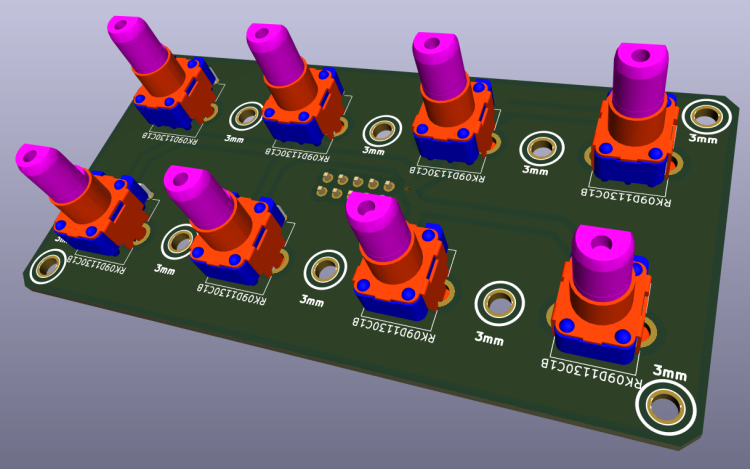
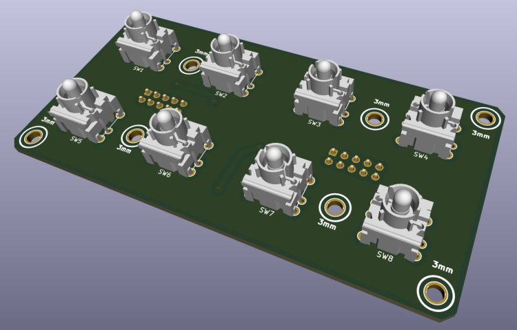
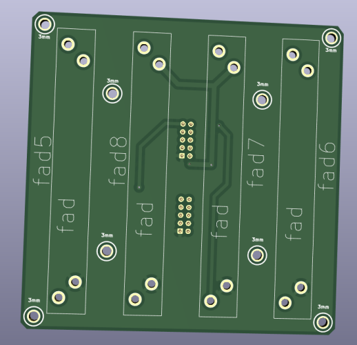
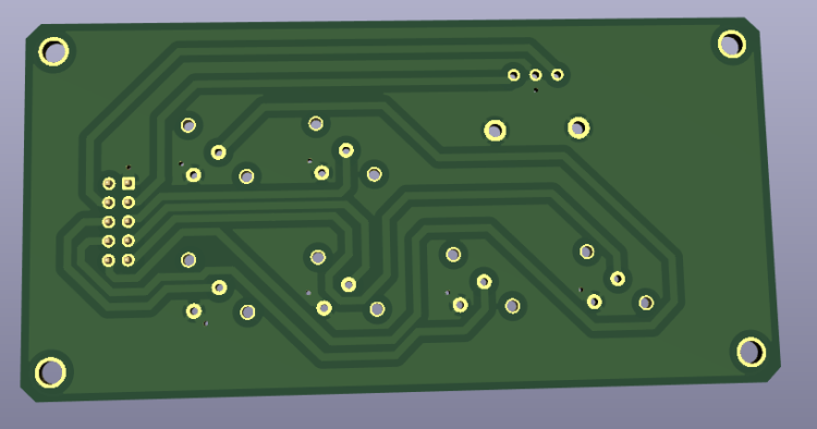
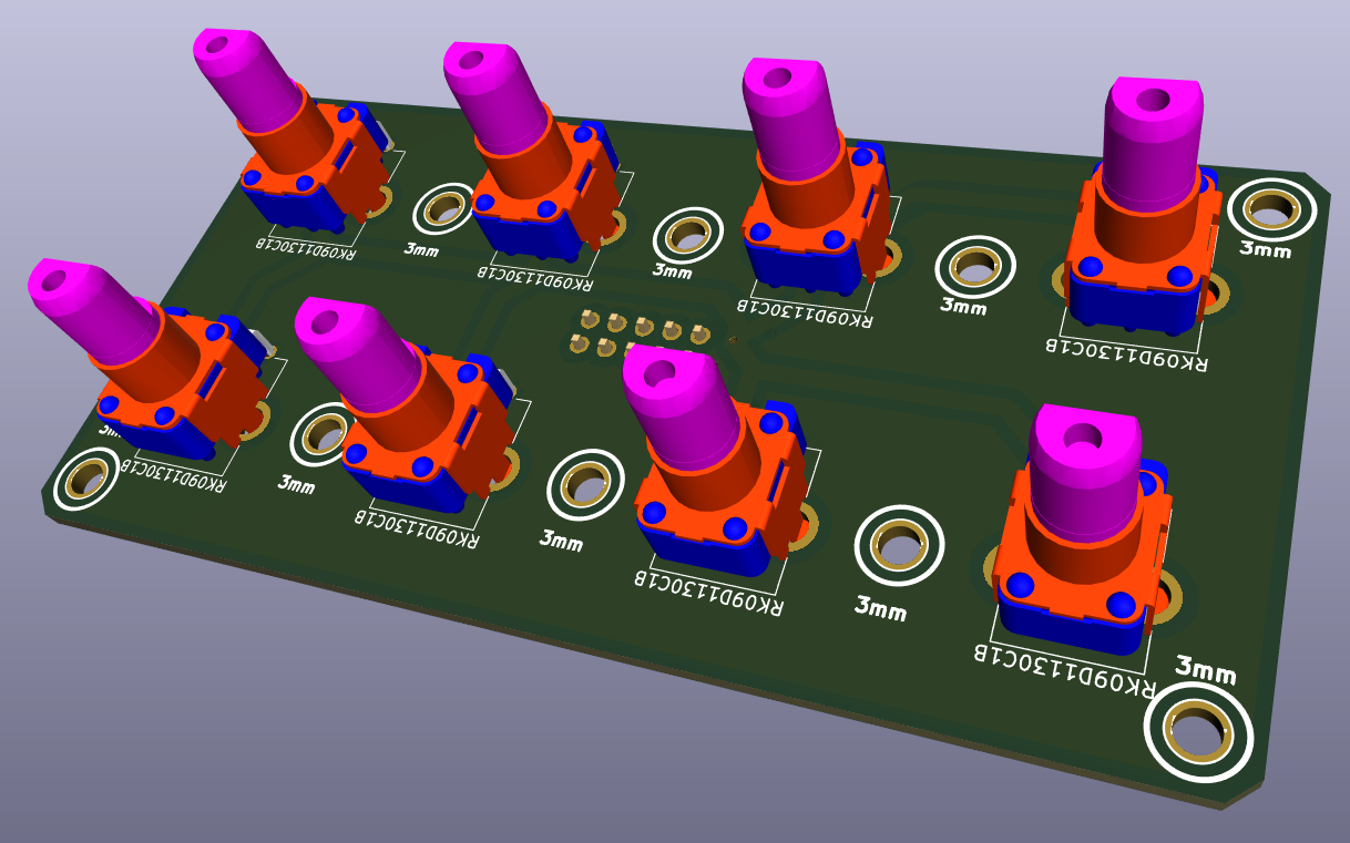
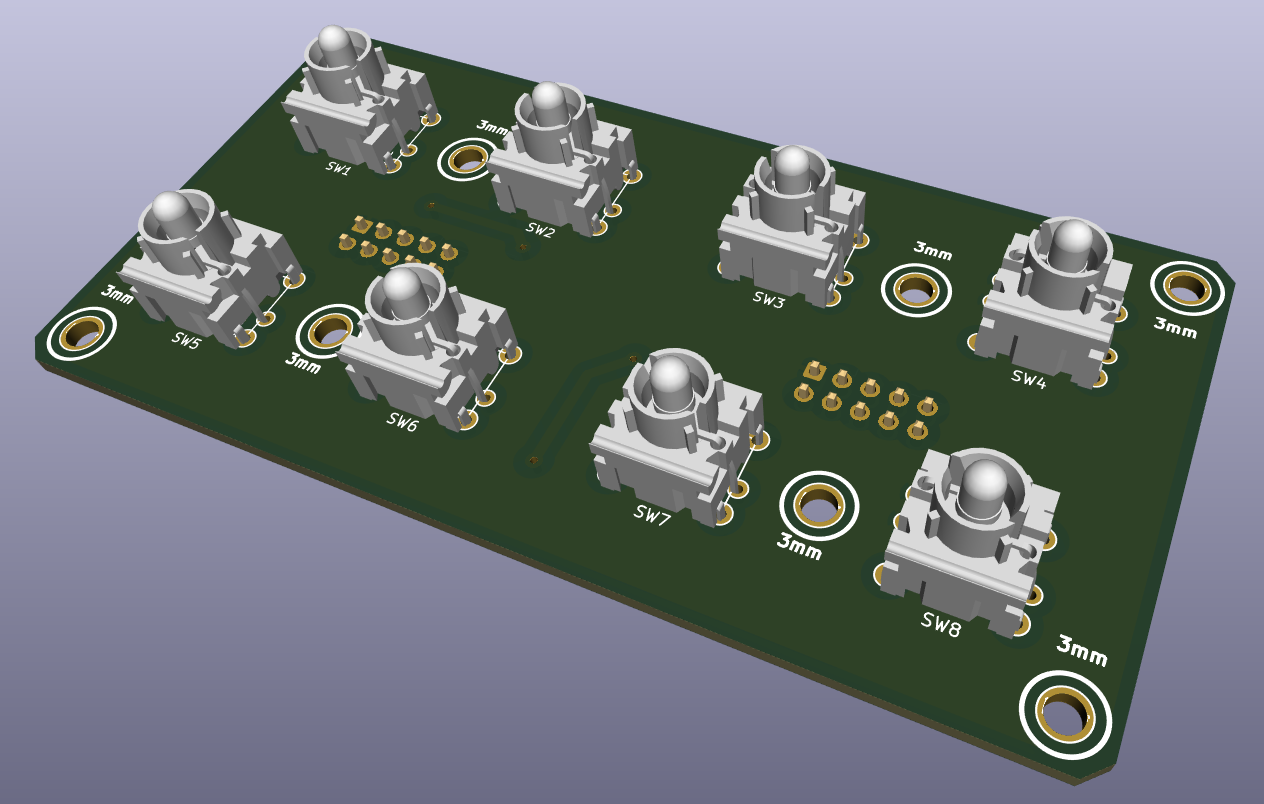
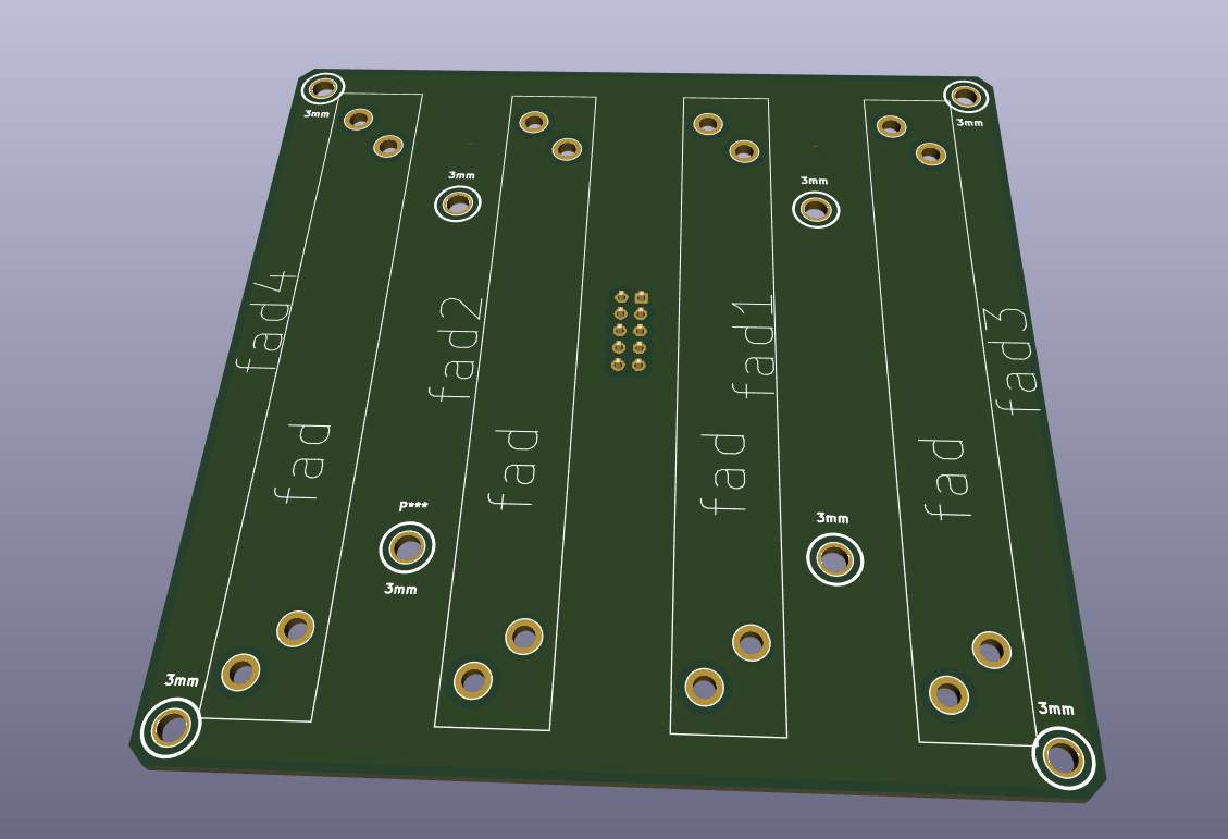
potentiometer : https://drive.google.com/file/d/1ThTC36WdYeexnTdHlgVoUhtVUv2OzcR3/view?usp=share_link push button https://drive.google.com/file/d/1pnDtaprQ3Mufdyg4ZW1S13UnAKqt1rC1/view?usp=share_link Fader 1 https://drive.google.com/file/d/1x0nXSRO_pQJPZEVyxlxVWuarjBzKPW2m/view?usp=share_link fader 2 (connect to fader1) https://drive.google.com/file/d/1npn4KlHNovZrZ0nFLKRoN7tZ-Jd0Pf2J/view?usp=share_link all files are here https://drive.google.com/drive/folders/1IZLVG2fVXstxGC9ZCWl0OCMjF7R1GEB3?usp=sharing thanks to you
-
Thank you for your involvement in my project. After studying novski's projects https://github.com/novski/Midibox/tree/master/VLR-8Enc It uses an uln2803 for the switches. I reproduced its layout, but I don't really understand how Darlington transistor arrays work. https://drive.google.com/file/d/1EW-IxclCJ1_cOeau-bTUnaOuSZ5eGdsN/view?usp=share_link I will study the solution you propose with 74HC1G14. you are right and will try to take your remarks into account. although I don't have a solution yet. the alps caps are pretty and I couldn't find a smaller equivalent. thank you again for your involvement The encoders and silicon pad modules are far from finished. the other modules are almost ok for me, I should check them again. maybe you can watch this if you want. but if you have little time, I would not like to waste it and keep the time you can give me to really check the modules that I think I have completely finished
-
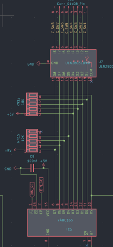
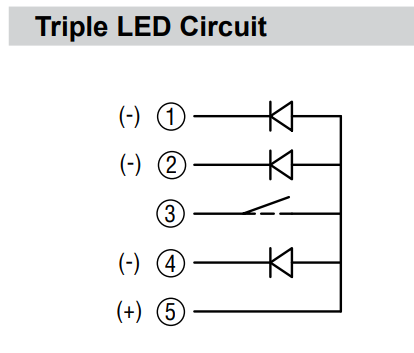
hello, always about 4x2 Enc RGB SW Led ring Rgb I abandoned the idea of a matrix for the rgb leds of the pel12t encoders. this simplifies the diagram. for the common anode I read here: http://midibox.org/forums/topic/20713-how-to-connect-common-anode-rgb-leds/#comment-180389 just connect the cathodes to the DOUT pins. 595s can sink current, which means they "can supply ground/0V". Thus, the output is "reversed" for common anode parts. This can be specified in MB_NG. When the 595 output is high, the LED is off. When low, the LED is on. On the other hand I still do not know how to connect the switch of the pel12t encoders to the 74hc165. normally a switch is connected between VS and D* with its switches the contact is between VD and D*. Is there a way to solve this problem in a software way? should I use a bc547 for example or other hardware solution? another possible solution? https://drive.google.com/file/d/1kLTryPKwxlgYORO9NTeJ00XRjq4Sl2w4/view?usp=share_link Thanks for your help
-
The module that gives me the most problem is the 4x2 Enc RGB SW Led ring Rgb https://drive.google.com/file/d/1kLTryPKwxlgYORO9NTeJ00XRjq4Sl2w4/view?usp=share_link I'm trying to use Bourns RGB + Switch Pel12T Encoders https://mou.sr/3zJilbU https://www.mouser.fr/datasheet/2/54/PEL12T-777462.pdf But the wiring diagram of the leds and switches of these encoders is a challenge for me: the RGB LED matrix is also difficult. Maybe it's not possible with a matrix because of the switch ? Help and advice are always welcome. and the lack of space on will also be a PCB challenge, I may be forced to add a third sandwich panel.
-
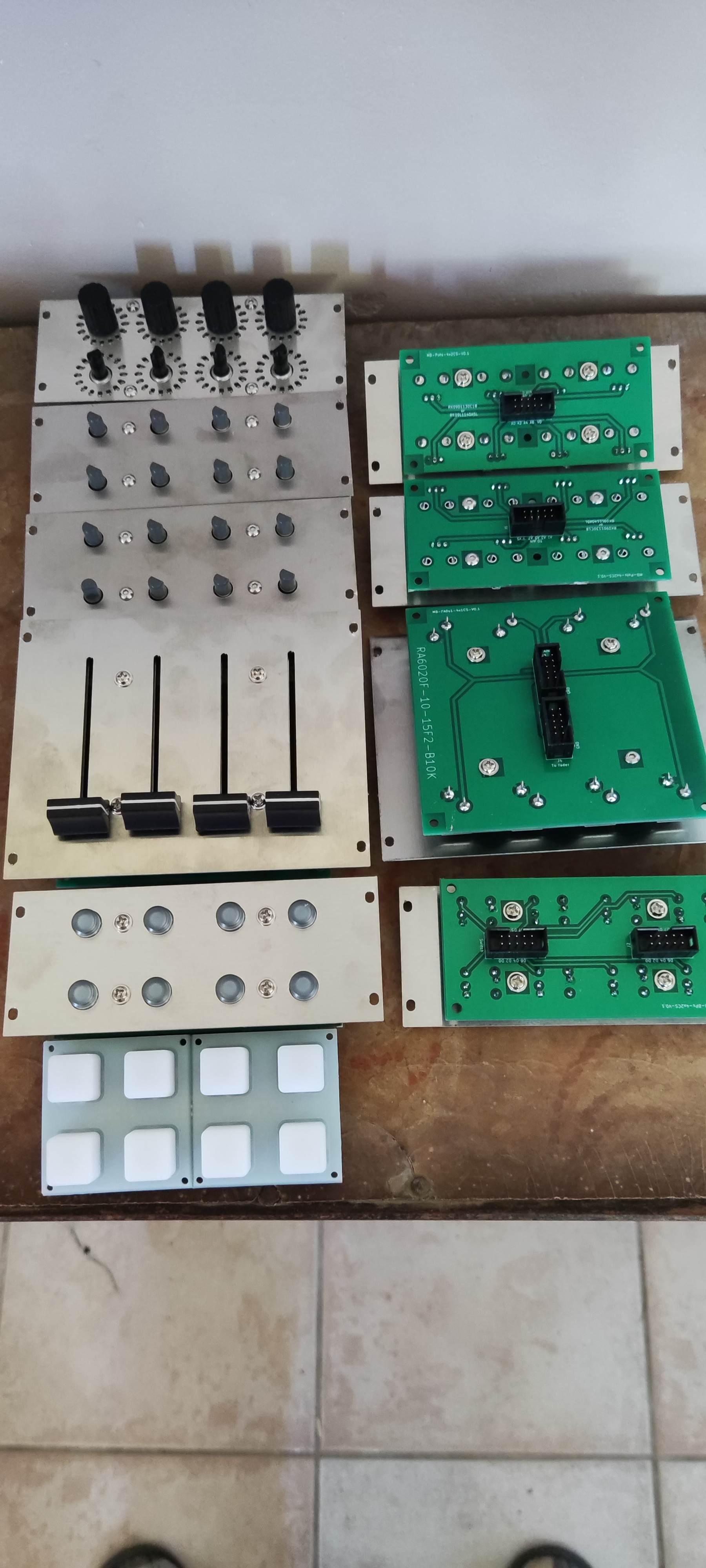
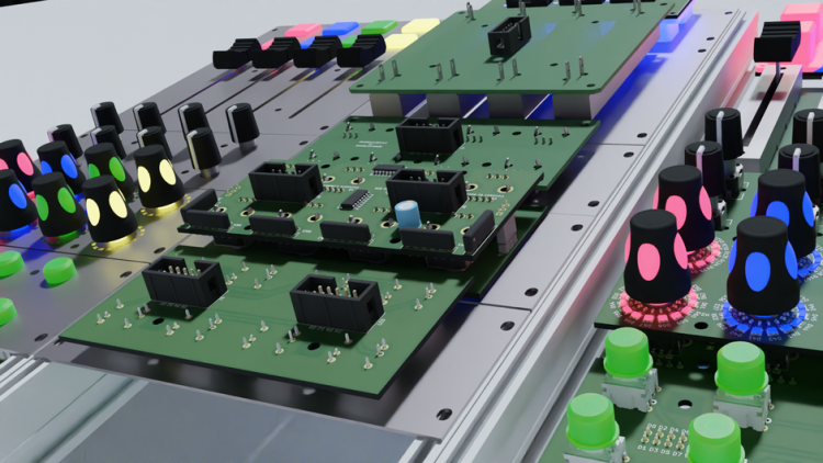
For fun, an overview of the modules already developed and under development
-
Thanks It's mostly to look at how you designed it. I would adapt it for the sparkfun 2x2 pads i would like to use it with rgb leds
-
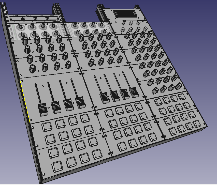
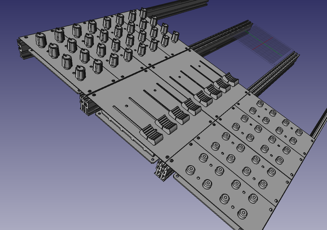
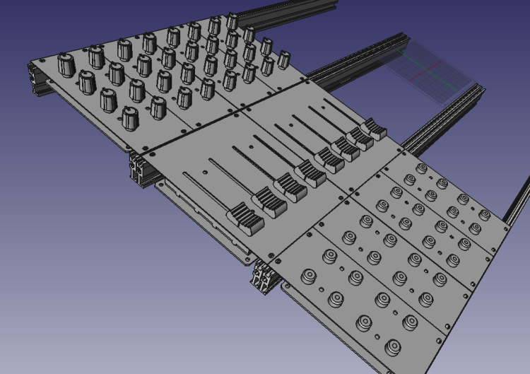
Good morning; Thank you very much for your answers and your help which are very precious to me. I tried to correct my files according to your advice. (in the previously shared folder https://drive.google.com/drive/folders/1IZLVG2fVXstxGC9ZCWl0OCMjF7R1GEB3?usp=share_link) (I upgraded to version 7 of kicad). I'm also trying to make a PCB with silicone buttons, (see in the TO_DO folder in the folder I shared) how to create a footprint in kicad for silicone buttons, (like you did here: http://wiki.midibox.org/lib/exe/fetch.php?w=600&tok=c1a13e&media=phatline:blm16x16-pcb-3d-front.jpg) Would you be willing to share your footprint? The files you will find in the TO_DO folder are in progress, full of errors and far from finished .... if you look at them, your advice is always welcome for fun, a vision of what my future controller could look like, disregard the screen at the top right, it could have a series of oled on the top

-
here is where I am at the moment: https://drive.google.com/drive/folders/1IZLVG2fVXstxGC9ZCWl0OCMjF7R1GEB3?usp=share_link i am looking for rgb leds it is listed here: http://www.ucapps.de/midibox_ng_manual_hw.html you need an external power supply. how to handle this? Thanks for your help
-
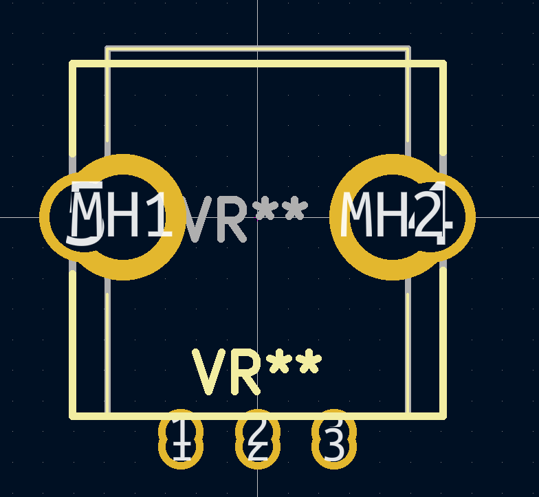
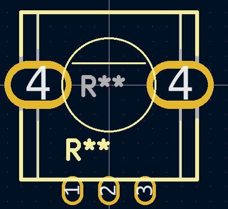
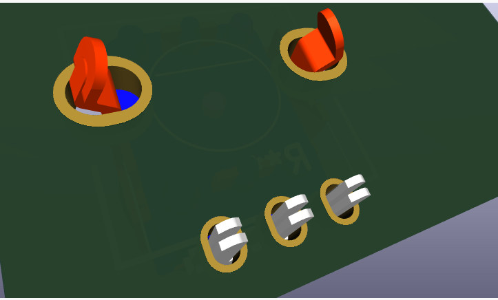
thank you for your reply I'm working on it : I noticed you don't like the MEC buttons, I'm looking at the alternatives. maybe cherry switches, I need to find some nice caps (any suggestions?) I want to merge 2 footprints for the potentiometers: (so that I can use different potentiometers) Is this a bad idea? should I connect pads 4 to the -? thank you for your help


-
Hello, I am currently thinking about a version 2 of my modulbox circuits V1: the objectives are: Have the circuits manufactured by a professional (for example: https://jlcpcb.com/). Have the fronts made by a professional. -Be able to more easily share the circuits created with the community The design rules remain the same: circuits of 50 x 100 mm or 100 x 100 mm max For the potentiometers I used: RK09L1140A2U ( https://www.mouser.fr/ProductDetail/Alps-Alpine/RK09L1140A2U?qs=6EGMNY9ZYDShe59Bf8g9AA%3D%3D ) paid 0.70 euros each at the time, they cost 2.80 euros today, I'm thinking of replacing them with RK09D1130C1B ( https://www.mouser.fr/ProductDetail/688-RK09D1130C1B ) they are cheaper. Do you recommend another model / brand? I'm thinking of trying to make a footprint that accepts several kinds of potentiometers. it's possible ? does it already exist? (I work with kicad) (for caps: https://www.mouser.fr/ProductDetail/Eagle-Plastic-Devices/450-4760?qs=J4wJDGtbthoFgTzq4MR8dw%3D%3D) For the faders I used: RA6020F-10-15F2-B10K ( https://www.mouser.fr/ProductDetail/Alpha-Taiwan/RA6020F-10-15F2-B10K?qs=6TczTpqoAMVgxoAgFDSJ8A%3D%3D ) It may not be the best choice. Do you recommend another model / brand? For the push buttons I used: MEC 3FTH9 https://www.reichelt.de/fr/fr/bouton-multimec-sans-clairage-connecteur-circuit-imprim--taster-3fth9-p156904.html?GROUPID= 7587&SHOW=1&OFFSET=16&&r=1 Do you recommend another model / brand? It also remains to update the standard control surface: I'm also thinking about possibly making a 4 x 2 sparkfun pads with RGB led ( https://www.sparkfun.com/products/7836 ) I still have a lot of work. Anyone interested in this project? People who would like to help me or simply control my work? or do you have any advice or suggestions? Thanks