

jarvis
-
Posts
23 -
Joined
-
Last visited
-
Days Won
3
Content Type
Profiles
Forums
Blogs
Gallery
Posts posted by jarvis
-
-
Thank you, TK!
-
In the options menu, #19 allows you to set the initial CC value for Clear and Init. Would it be possible to either make another option for the PrgCh default value or to use the CC settings for PrgCh as well? When assigning PrgCh to a track layer it defaults to 0 for all steps, so right away a PrgCh message of `0` is sent. I think it would be more ideal for the default value to be `---` so that the PrgCh messages would have to be explicitly set on a step.
-
Disregard that question - I figured it out. This sequencer keeps amazing me!
If anyone else hasn't figured it out:
On your target track (the one with the notes you want to play), open the mode menu. Set mode to 'normal', select a bus, and change STrg to 'on'.
On your 'step' track (the one to advance the steps of the target track), open the event menu. Select the bus you specified for the target track. Now any steps you enter in edit mode will cause the sequencer of the target track to advance a step.

-
Would it be possible to decouple a track from the master clock and advance the step from another track? I know it sounds unintuitive, but one of the most fun parts of the sh-101 sequencer is the ability to advance through the steps with an external trigger source like an 808 or 606. This allows for some really interesting variety for a relatively simple sequence (I always think of them as 'rolling' sequences).
For a 4 step note sequence ABCD And a 16 step trig sequence *--**--*------*- *--**--*------*-|*--**--*------*-|*--**--*------*-|*--**--*------*- A BC D A B CD A B C DA B C D AB C D -
I appreciate the fast bugfixes - thanks @TK.!
-
I did quite a bit of searching for these but I think they are custom extrusions. They are fairly simple but clever interlocking sides that seem to be adjustable to whatever angle you may need. I emailed Heidenreich about them a while ago but never heard back, and talked with a fabricator friend of mine who said he didn't think they would be common profiles.
On 1/12/2018 at 0:30 PM, Airyck said:I have everything ready to go except the aluminum extrusion profiles and I'm having a hard time finding any what will work :/ . Is there any chance anybody could point me to where I can find some or how to have them made?
-
 1
1
-
-
I found a bug in v4.095pre6 (using Wilba CS) where all encoders become unresponsive after using live record. The encoders appear to work fine until a note has been recorded - after this they become unresponsive. This seems to be the case only when notes are recorded while the sequencer is playing.
-
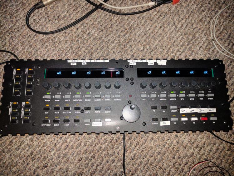
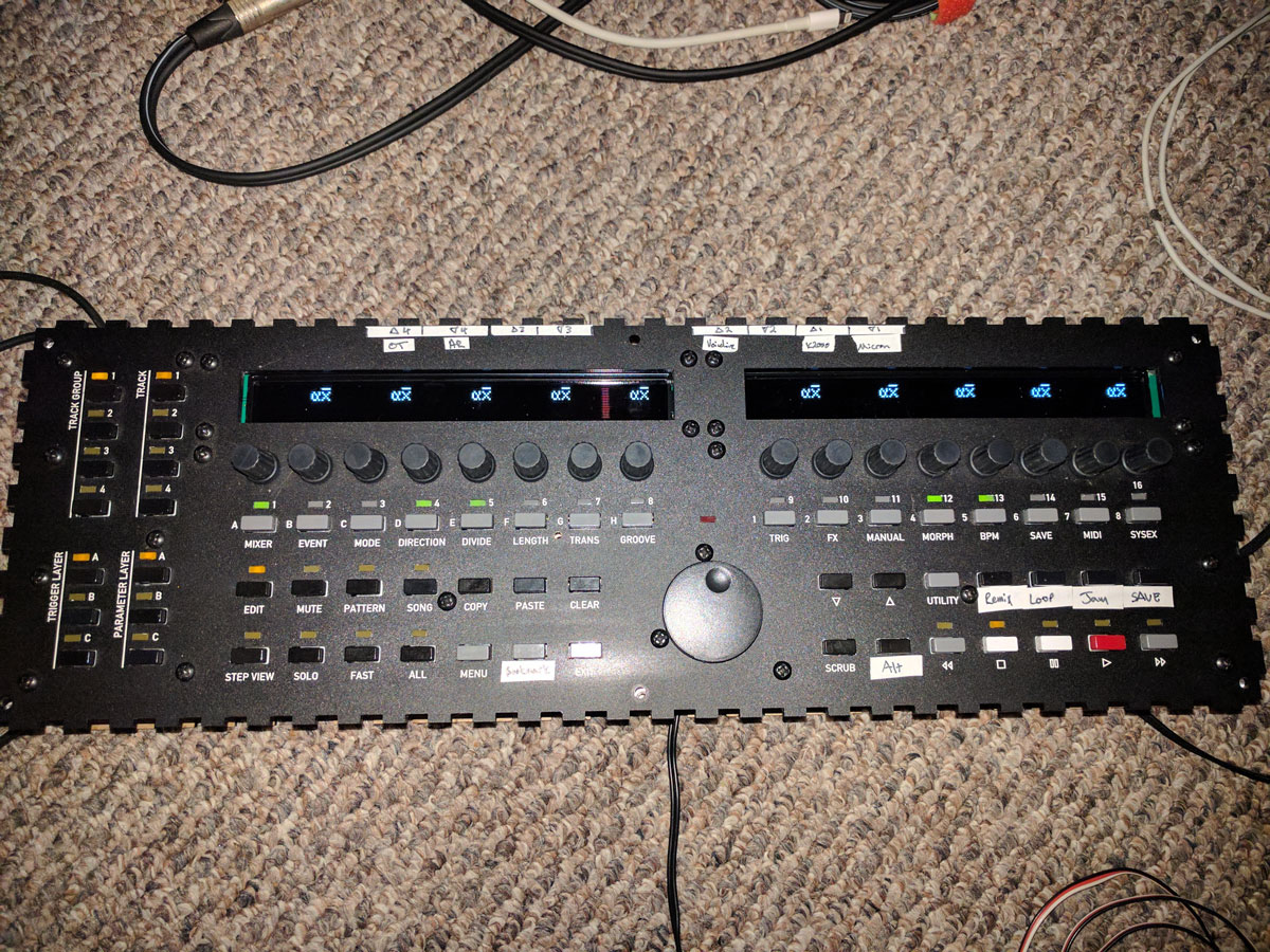
That's great news! I really like the modular layout and the backlit buttons - nice work!
-
On 8/6/2017 at 4:06 PM, FlavioB said:
Hi ppl.
I'd love to be able to set "first/last step" on a pattern - can this feature be added somewhen?Thanks,
F.You can do this in the 'loop' menu in FX. It can be applied to just the selected track or to all tracks in a pattern. I use it quite regularly and have the loop toggle as a hot key on my panel - lots of fun!
-
On 6/2/2017 at 4:09 PM, latigid on said:
The idea uses a DK-38 knob from ALBS, and I've asked Adrian to accommodate for it by cutting a hole in the front panel. So it will already be sunken down a bit. But no, it's not flush with the panel. They also have a fairly long stem, which is why the wheel on the Wilba version is "panel mounted" to the PCB.
Do you know of a datawheel knob that sits lower? Please tell me a part number and I'll have a look.
I'm not worried so much about the encoder values being bumped, its more about ergonomics. The USB jog wheel you shared was nice, but it has rounded edges on the jog wheel as well as a contoured surface. Combined, these features give more room for finger placement. Now imagine that same layout with a square-edged knob and flat control surface - its not a negligible loss of space.
I don't know of any better solutions except a flat data wheel (I got one at Adafruit but it has a long stem - I'll have to scrounge up the part number) and/or more space between the jog wheel and buttons. I'm by no means speaking from a position of experience, it's just something I noticed that might be worth checking out.
-
My main concern with the design is that, at least according to the renderings, the data wheel is not flush with the surface of the case. I would expect this to lead to accidental knob nudges when pressing the frequently used function buttons surrounding it, or at least make some of the ergonomics a little odd since you have to angle your finger around the edge of the data wheel. Is there other hardware you've modeled this layout after?
-
quite excited by the new layout, excellent work!
-
That looks great, definitely interested in one!
How do the panel and extrusions interlock? It seems to be friction fit and all held together by the side panels. Or are there blind screws where the panel and extrusions overlap?
-
I switched from 5v to 3.3v and now they work fine

So, my experience is that the Raystar White OLEDs work(ed, before the power zap) at 5v with power provided through an external regulator (Murata 5v switcher external to the DISCO board), and that the Raystar/Vishay Yellow OLEDs work at 3v3 with no external regulator (straight off the DISCO board). This is very strange since they are both spec'd at 5v.
But hey, it's working–I'll take that. A responsive display is such an improvement to the user experience!
-
On 11/12/2016 at 6:32 PM, mongrol said:
@tk. Yep, these Oled's were perfect before I b0rked by discovery board. I'd forgotten about the 0x02 though... so...
- Uploaded boatloader_update app
- Set lcd_type 0x02
- Store
- Reset
- Looked back in my enclosure thread and checked my previous voltage for my oled's (it's clear it's 3.3v on the pic).
Both screens still won't work at the same time. I remember having a helluva time when building this first time around and somehow in my build thread I came up back to 5V and 0x02. However, every photo I look back it it's clearly set to 3.3v.
Time for more oxygen I think.
I am now having this exact problem - I too accidentally fried my Discovery board (the previous revision) and now the OLED displays do not work with the new Discovery board (the latest revision). I even tried replacement displays (Vishay from Mouser) with no success. I am back to using my old/slow LCD's from buydisplay.com
Is it possible that this is a compatibility issue with the current revision of Discovery boards?
-
For my situation, I have determined it was in fact a power issue. I added an extra regular for the OLEDs which draws directly from the external power supply in order to bypass the built-in regulator on the STM32F4 Discovery board, and it now everything works correctly. I have also set the lcd_type to 0x02 in the bootloader.
So, in order for the Raystar OLEDs to work correctly, they need to be fed 5v and to be externally regulated. I wish I had exact specs for current draw, since this means the OLEDs are drawing more current than cheap LCDs they replaced. It might also be that this specific color variant draws more current than the others. In my case, I am using white on black OLEDs. The OLEDs look and refresh significantly better than the cheap LCDs they replaced, so I see it as worth the extra effort.
FWIW - I would not recommend these white on black LCDs from buydisplay.com - the refresh rate is terrible and there is significant bleed from the backlight
-
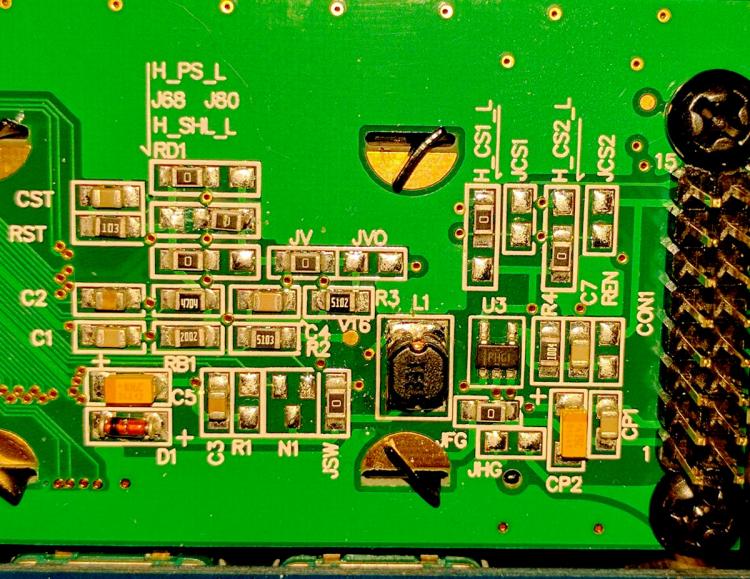
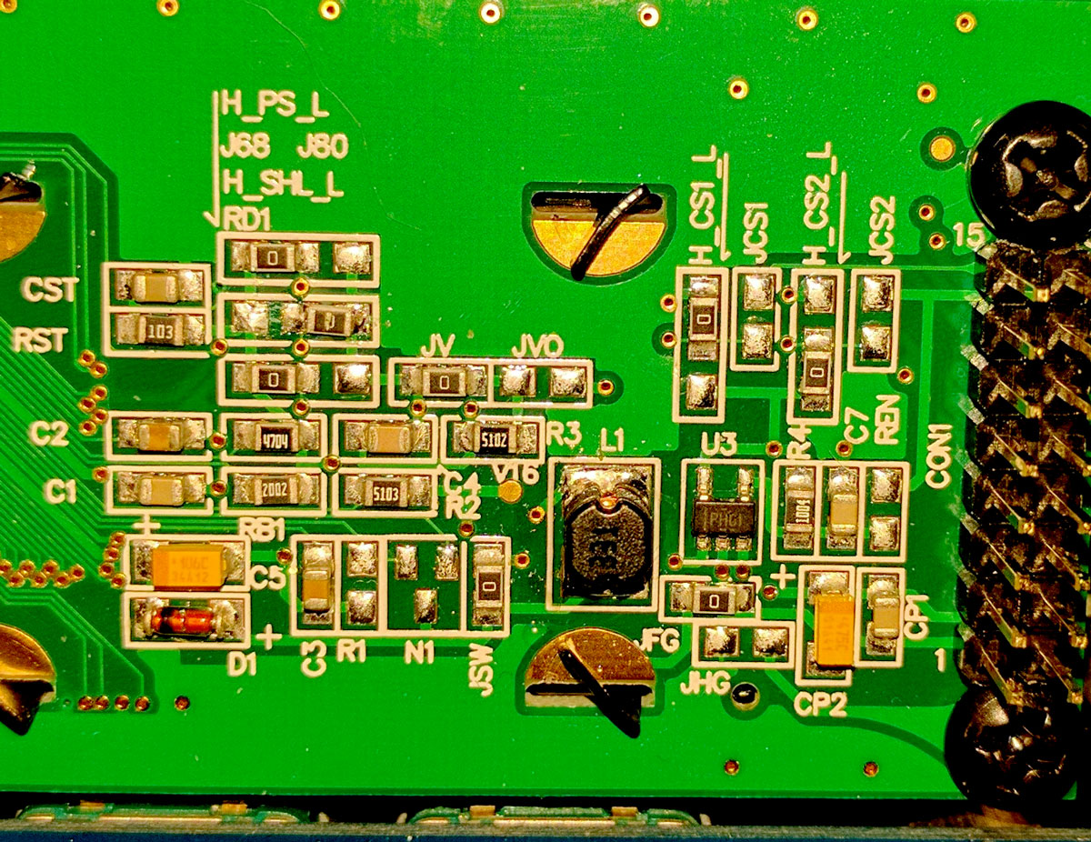
@mongrol Thanks for the datasheet! Based on that, the Raystars operate at 5v.
@Altitude & @TK. Yes, I think you are right in that it is a jumper. There is a spot marked J68 J80. It was factory set to J68. I changed this to J80 and now both LEDs will operate at the same time, but they are not displaying anything resembling the correct characters and do not update after the Seqv4 has started
-
I have an email out to the company. Unfortunately they do not seem to have detailed electrical specs on the datasheet or website.
http://www.raystar-optronics.com/products-category-detail.php?lang=en&ProID=296
The part# is REC004002AWPP5N00000.
Code system here: http://www.raystar-optronics.com/down.php?DID=6 (triggers download of PDF)
It appears to be 5v, but current draw is not clear
-
I recently got some white Raystar OLEDs and am having trouble getting everything to work right.
When I have the power at 3.3v, both displays start up fine but as soon as it loads the Seqv4 app it immediately reboots. If I start up with only 1 LCD connected at a time, the boot sequence works just fine.
When I have the power at 5v, the Seqv4 app loads fine but only the left display functions correctly - the right one shows some random characters.
I have set the LCD type to 0x02.
I have tried powering both with USB and external power. Is this maybe a current draw problem?
-
I'm in for 2x white 40x2 displays. If there are not enough requests for the white ones to hit 10, then I will fall back to green.
-
Found these VFDs (CU40025-UW9J) on eBay. I emailed Noritake and asked for the datasheet as it's not available on their site and it seems to just be the obsoleted predecessor to the current version (CU40025-UW6J). I can't confirm they work, I just thought it would be a good lead to share, especially at $12/ea
-
Anyone have a clue what the adjustable angle aluminum extrusions are that are used for the corners? That's the key to this case... it would be nice to find those and just get the panels/ends cut locally
-
1
-
MIDIbox SEQ V4 Release + Feedback
in MIDIbox SEQ
Posted
Minor request:
When using a track to control the clock division of another track, the values are offset by -1 from the settings in the clock divider menu. For example: setting a value of 16 in the sequencer sets the clock division to 17. Would it be possible for the values in the sequencer to match 1:1 with the value of the clock setting menu?
Thank you as always for your continued efforts :)