rosch Posted February 3, 2009 Posted February 3, 2009 hi people,here i'll show how i'm building my very first midibox, a minimal control surface one-bankstick mono SID V2 !!! after asking some questions about whether doing it modular or with 6582 pcb and parts kit i actually know it would be better to chose the all-in-one solution due to error reduction in a one pcb unit. and i still intend to build me a 8-SID Wilba style 6582 megasynth... but not this month :(needing badly one more good midi keyboard controller i spent too much money on an ebay auction and bought a sample keyboard this month. so it was clear that i'd have to wait till i can afford all parts to build my 6582......but lurking around here all the time and reading about people building kits and having trouble and solving problems i just couldn't wait without doing that too, at least the smaller way for now.so i ordered some cheap encoders at pollin's, just one PIC18F4685 at SmashTV's and the rest (pcbs and kits for 1 core, sid, bankstick and dinX4) at Mike's store and today he already called me to pick up my midibox pack :Dhe's just round the corner from here so i met him tonight and bought my sid stuff and some additional cables etc, we had a hot coffee and he showed me his small pcb factory and some of his other cool projects. hey i didn't know he's doing pcb service where you can give him your eagle layout and he'll do the rest! so at the moment i'm busy sorting out the material and as soon as there's something to show i'll upload some pics which i have to admit won't be of good quality at all (cell phone)i haven't made plans for a comfortable housing yet, but i've seen 1HE rackspace wouldn't be enough because of the 2x20 lcd display (plus the knobs underneath it but the display itself is already too high for 1HE)any hints or good ideas would be very much appreciated! yeah!
stryd_one Posted February 4, 2009 Posted February 4, 2009 I've got several synths with 2*xx CLCDs on them which are 1RU high :)Not much room for knobs there though. Anyway, 2RU racks aren't a lot more expensive, so you could always go that way :)BTW, does the wiki work now?
rosch Posted February 4, 2009 Author Posted February 4, 2009 yes it was the special letter, but it's all running now! thanks for your help!in this case building the small sid has been a quick decision due to lack of money but need for sid... i like rack mounted devices so that would be first choice. and 2RU wouldn't be a problem, as you say, for there are so many features that can be added afterwards without need for a completely new surface then. i'm also following m00dawgs PSU thread, an important topic to me... there's a lot to learn. now that i have the original sid & core kits including regulator chips i'll use the original C64 supply for this one so i'll have to build me a custom device with separate transformers later for the 6582 where +/-(?) 12V reg should be included with regard to adding some analog filters then, too. but that's future.
rosch Posted February 6, 2009 Author Posted February 6, 2009 i've built a CORE, SID and DINX4 and here are the promised pics... in promised poor quality atm... meanwhile i've ordered one more SID kit at Mike's to have at least a stereo SID. now i have some questions:1. does the 2nd SID make changes necessary? i read about buttons to switch from stereo to 2xmono and an additional LED to show the mode... so i think the buttons are no problem, i've built a DINX4, stuffed completely. but for the 1 LED i'd already need a DOUT i guess??2. is it ok to build a complete DINX4 while using only a part? but somehow silly not to make use of the possibilities, but i thought it's better to build it in one run. so if it's dangerous or likely to cause undesired effects, i'll have to look for some more knobs etc to make use of the whole thingso let's have a look at some pics! all without cables, but i'll have to wait for my PIC anyway...SIDV2d.JPGdinx4a.JPGSIDV2d.JPGdinx4a.JPG
rosch Posted February 6, 2009 Author Posted February 6, 2009 few more...COREb.JPGSIDa.JPGCOREb.JPGSIDa.JPG
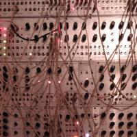
rosch Posted February 6, 2009 Author Posted February 6, 2009 that's the control surface pcb, i'm trying how to put the LCD between the buttons. don't laugh, it's my first try!edit: also first try posting pictures, next time i'll reduce them... PANEL1.JPGPANEL2.JPGPANEL1.JPGPANEL2.JPG
stryd_one Posted February 7, 2009 Posted February 7, 2009 2) Yes that's fine, just don't stuff the unused shift registers :)
rosch Posted February 7, 2009 Author Posted February 7, 2009 2) Yes that's fine, just don't stuff the unused shift registers :)umm, i have them already filled to the brim, but i'm actually using just 9 buttons & 1 encoder at the moment ??? that would mean-either get a new DINX4 and stuff it just partly or-get a DOUTX4 to be able to use LEDs so it makes sense to add knobs & encoders.i think the 2nd's better :) haha it's becoming bigger every day my minimal least cost SIDV2 :D
rosch Posted February 7, 2009 Author Posted February 7, 2009 my encoders also have a push button function. now i'm just wondering whether it's useful to use them as buttons, too.has anyone made experiences with that?perhaps confusing?or would you expect value changes when just intended to push a button? mine are very sluggish in detented mode...edit: or perhaps need to hold a button down while changing a value??
Flemming Posted February 7, 2009 Posted February 7, 2009 I thought of using encoder with push-button too... my Micron synth has such a pushbutton encoder, which is pretty annoying but still very welcome considering the small amount of controls on it generally - i may feel the same about minimal surface for MBSID; a pushbutton extra could never hurt :) you can decide for yourself what function it should have.. did you have a look at the 'setup_*.asm'-file?? there you can easily see what parameters could be assigned to the pushbuttonYou could also just not connect it to avoid clicking it by accident...My first hope was to change the 5 buttons under the LCD with encoders - It would be nice with more knobs, it's easier to have direct access to the menu parameters... but i'd have to do some serious changes in the firmware which i'm pretty sure i won't be able to manage for now
rosch Posted February 7, 2009 Author Posted February 7, 2009 yes i also thought of additional encoders that correspond to the writings on the LCD, but when looking at TK's complete control surface i noticed that for different functions there'd be different encoders and i'd have to change assignments what i'm not able to. i think i'll better do it the way it is recommended. buttons as buttons & encoder as encoders, but in this case ...MORE!!!so now i'm going to add LEDs too. i'd prefer red ones. is there anything to know about them so one would rather take others (like the blue ones being both bad taste and bad to the eyes) ?
Flemming Posted February 7, 2009 Posted February 7, 2009 What i meant was, instead of having to press the first button in order to manipulate the first parameter on the display using the encoder, i would much rather just turn the respective encoder.... no assigning nothing to any knobs :) so to say, the 5 buttond beneath the LCD would be encoders instead.... which function they have is dictated by the text in the display. I'm not even sure it's possible but i'll have a go at it when i'm more experienced with messing with the sourceI was not trying to persuade you :) go for what you like best!! You will be the user of it so i think it's very important that the CS suits your taste and needs
stryd_one Posted February 7, 2009 Posted February 7, 2009 so now i'm going to add LEDs too. i'd prefer red ones. is there anything to know about them so one would rather take others (like the blue ones being both bad taste and bad to the eyes) ?I can't think of anything at all.... except maybe if you work in a brothel, teh red background lighting could make the contrast a bit low ;)
rosch Posted February 7, 2009 Author Posted February 7, 2009 atm i don't know how to do it at all- i've made a mistake with the DINX4,so i will have to expand the control surface to some degree. the encoder/button combination was just a thought..., but i have 1 important question right now:is it possible to take for example just the FILTER and LFO section and give them buttons, encoders and led while having the OSC and ENV sections still accessible via the LCD encoder & buttons like in step A? these & the MM are options i could expand to in the future. i hope such thing can be done without completely rewriting the menu structures..?thanks
rosch Posted February 7, 2009 Author Posted February 7, 2009 I can't think of anything at all.... except maybe if you work in a brothel, teh red background lighting could make the contrast a bit low ;) :Dedit: removed inappropriate indecent allusion ;)
rosch Posted February 10, 2009 Author Posted February 10, 2009 today i 've made the decision to step-C upgrade my little now to be stereo MBsid and ordered all parts that hadn't been designated to be in before at mike's. so maybe he'll call me by end of the week...this time i will favour the stand alone version over having it rack mounted (a quite unusual decision to me as a rack enthusiast) because i have here a very nice old tube radio housing. it's actually a wooden frame with round corners ??? and enough room in it to put in a whole bunch of SID and cores plus finally AOUTNG+ the required magic SSM filters by seppoman!!so, finally knowing the control surface and case i'll use i can start the work on my frontpanel which will be very custom diy! more pics will follow in a few days i hope...@ Flemming:still thinking about your idea regarding the encoders below the LCD (2x40??). ok it won't happen in this my first project but later when having learnt more about knob / enc assignment etc i'll probably go for something like that, if possible. but imagine them with both functions, e.g. the LFO depth encoder used as button to swap the waveform etc. you'd have the leds near the enc. and that would perhaps be possible without changes at all, because you'd need a button anyway... how about that?my fear was that you could easily change values without intend to by pressing the button. but having removed the detention of some of my panasonic encoders i think they're still detented enough to not change value too easily. but i haven't had any others till now...
jooks Posted February 12, 2009 Posted February 12, 2009 Looks good rosch! I will watch this build with great interest :) I´m very interested to see your case. It´s so much fun thinking about possible cases. Nowdays I can go into a boring second hand shop and find lots of interesting synthcases!I´m also very tempted to go stepC instead of stepA but the amount of wiring scares me....maybe if I succed making the bankstick module and the opt.64PSU I will get the curage needed ;)
stryd_one Posted February 12, 2009 Posted February 12, 2009 Don't be spooked bro, it ain't so bad. Getting some practice on less gnarly stuff as you said, is a great way to go :)
Flemming Posted February 12, 2009 Posted February 12, 2009 Don't be spooked bro, it ain't so bad. Getting some practice on less gnarly stuff as you said, is a great way to go :)I myself is also pretty scared of CS step C :) i just have no clue, hehe... i will start out with step A to get some practise and later on i will upgrade to step C@Rosch - i think our ideas is somehow different. I would not use LEDs or buttons as the knobs parameter and value is allready on the screen... like this ----------------------- | Dly Atk Dec Sus Rel | o ----------------------- o o o o o So if i want to adjust sustain i can just tweak the 4th knob instead of having to push the 4th button and THEN adjust sustain by using the single encoder to the right of the display. This way i could also adjust both Atk and Rel simultaneously... now i have to push the Atk button, adjust with encoder, push Rel button and adjust encoder.. But i'm not even sure it's possible without severe knowledge about MIOS programming :) it might just be another one of my goofy ideas
rosch Posted February 12, 2009 Author Posted February 12, 2009 the idea is good, it's like on an analogue synth. one would need to rewrite parts of the menu structure to be able to skip menues by touching an additional menu button. so that's far too much for me atm :) but perhaps some day...now i've looked which buttons are not used in button-encoder combinations like the menu button for example. i'll leave the menu buttons and enc as they are, the same with the SID nr and up/down & shift.but for all other buttons like these in osc, env, filter and lfo section i'll use the buttons provided by my encoders without having to rewrite code for that purpose (at least i hope so). that's similar to how Vinyljunkie has done it several months ago as i just found out by doing few searches:http://www.midibox.org/forum/index.php/topic,12065.msg104668.html#msg104668but of course, having the control analogue-synth-like would be very great, but to have it perfect i guess we'll have to wait at least till the 32bit era, perhaps you can then use some more displays too (dreaming)
rosch Posted February 20, 2009 Author Posted February 20, 2009 update: now all PCBs from Mike's are soldered: 1x CORE, 2x SID, 2x DOUTX4 with the bridges for modulation matrix and 2x DINX4 + 1x DINX2 for step C ctrl surface.i just learnt that i don't need the rectifier / vreg circuit on the core pcb when using the original C64 psu. so i'm thinking again about using trafos for each voltage, depends on finding some quite fast...2 important questions for today:a) i've searched everywhere in forum/wiki/uCapps for a description of the transistor driver circuit for the LEDs in the modulation matrix, but haven't found anything... does anyone know where to find information about that? b) would the use of low current LEDs in the MM require change in resistor value (220ohms)?thanks!DSC02074.JPGDSC02075.JPGDSC02074.JPGDSC02075.JPG
Recommended Posts
Please sign in to comment
You will be able to leave a comment after signing in
Sign In Now