Leaderboard


Popular Content
Showing content with the highest reputation on 04/23/2016 in Posts
-
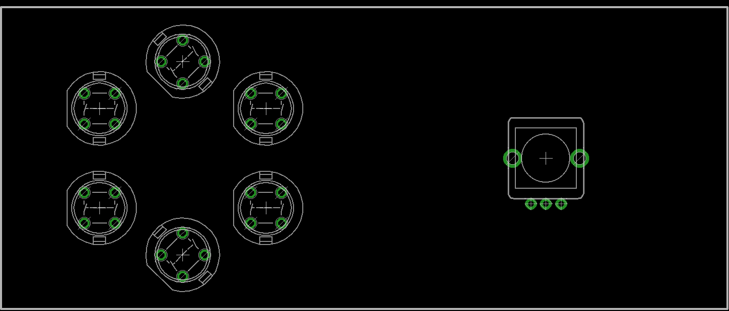
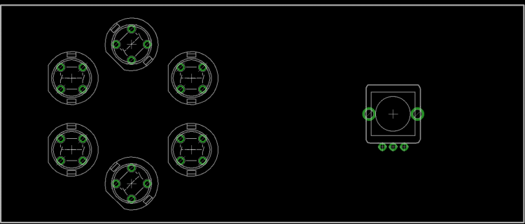
I'm working a bit with @Hawkeye and @jojjelito on their awesome MB-Programma project, only we'll try to use my illuminated encoders in place of the sadly obsolete LRE boards. The Programma makes good use of displays mounted at 45 degrees to label each encoder. But to do this it requires quite a mishmash of wiring. I propose a new PCB set to make things easier, not just for Programma but a range of NG builds. I'm still working on the 45 degree board, but I have a fair idea of the others should work. Here's how 4 OLEDDs look. This 7-pin type is very common and quite cheap. Spacing is at 30mm on a 120mm PCB. I thought it would be interesting to combine a sort of SCS, a bit different in layout to @ilmenator's. 10mm switch footprints will also be added. You could split the SCS over two PCBs (using a single ribbon with two connectors on it) or a single PCB if you liked. Once you go over 8 OLEDs, you need to start using DOUTs to generate the #CS (chip select/slave select) lines. It was mentioned that the Programma had a few issues with signal integrity, so I thought it might be an idea to combine a line driver with a shift register chain, and also an optional power regulator circuit. Adding to this, the new F4 Core J10B doesn't use 1:1 pinning with J1 on a DOUT board, so would need a special cable. I found some discussion that a similar circuit using 541 drivers and 1k output resistors could happily drive an array of displays spaced 10 metres in each direction. The resistor also acts as "termination" which attenuates reflections in the data lines. I will also add RC termination on the carrier boards. I didn't buffer the 595 outputs as they have reasonable source current already and #CS is less critical for timing. Apparently the displays run at 22mA each, so a linear Vreg should be okay to drive 32. Standard ribbon wire can take 500mA per per strand, again we should be okay, but I'll put an alternative power option on the carrier board. Two driver boards could be chained for a possible 64 OLEDs (!). If possible I will try to connect the remaining #CS lines so one could drive 8 additional displays, though I think 64 is the limit. @Hawkeye suggests that it's better to use #CS from one source only to avoid problems i.e. directly from J15A or DOUTs. Any questions or comments, please share!
 1 point
 -
To post the debugging here too from the german topic ... I used the MIOS Terminal to route a midikeyboard from IN1 of the first Midi IO board to OUT4 on the second Midi IO board with set router 1 IN1 all OUT4 all It worked just fine ...1 point
-
Thanks Peter! C coding I can do. I'm aiming for the STM32F4 based core, so fingers crossed, sounds like I could get it to work. The other one I was looking at was this little guy, but messing with flat cabling seems like a touchy proposition. Besides which I can't even find a place that supplies zif connectors with a .7mm pitch. Anyway, thanks for the pointers and the welcome!1 point
-
Hi Karg, i assume that you uploaded the right firmware .hex file with mios studio AND copied the right config .v4 file to the sd card. If all of your buttons work right this should be the case. But you wrote that you did not solder in all leds yet, and i think this is the problem. Im not 100% shure but on a multiplexed circuit, leaving out one led will affect all the others in line ont the pcb track and will so create some strange effects on your panel. Perhaps somone can confirm this. Much luck gridracer1 point
-
If you can verify that the hex is written, it should be okay. I think the point of selecting the device (manually) is that the burner knows what programming voltage to use.1 point