Leaderboard

Popular Content
Showing content with the highest reputation on 11/02/2017 in all areas
-
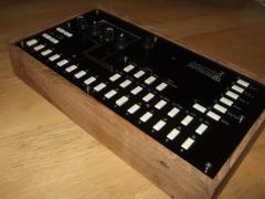
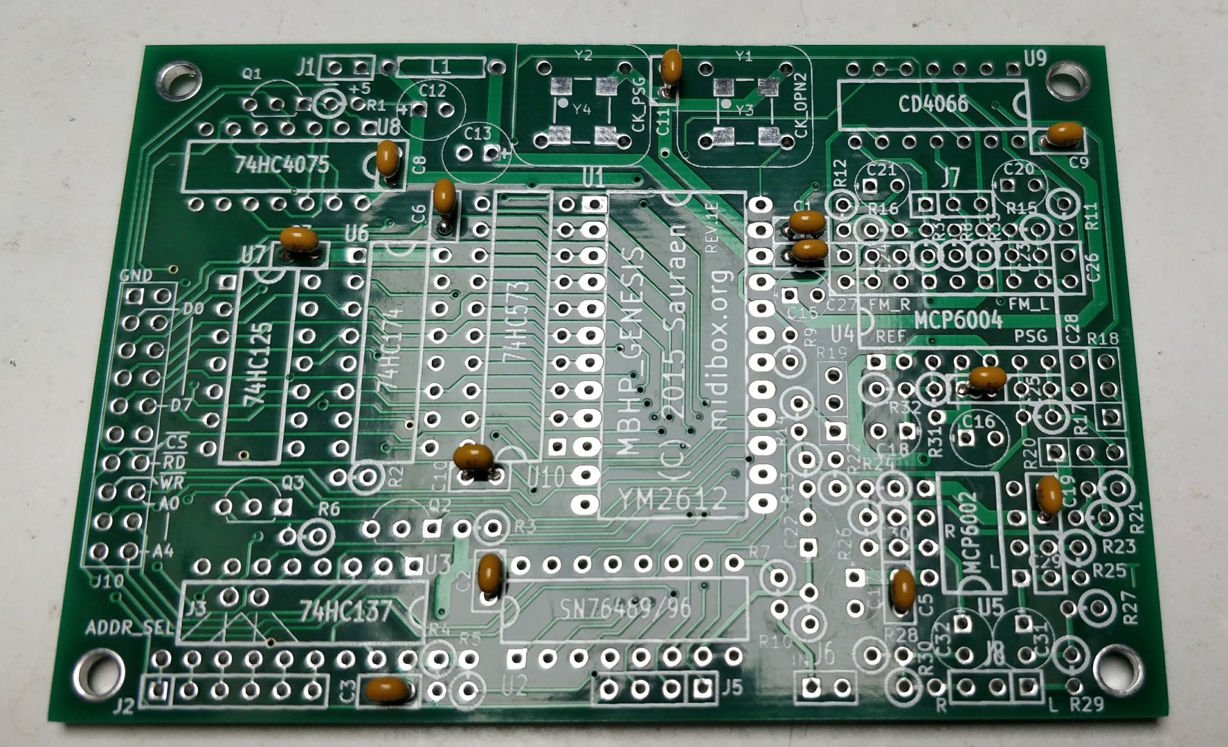
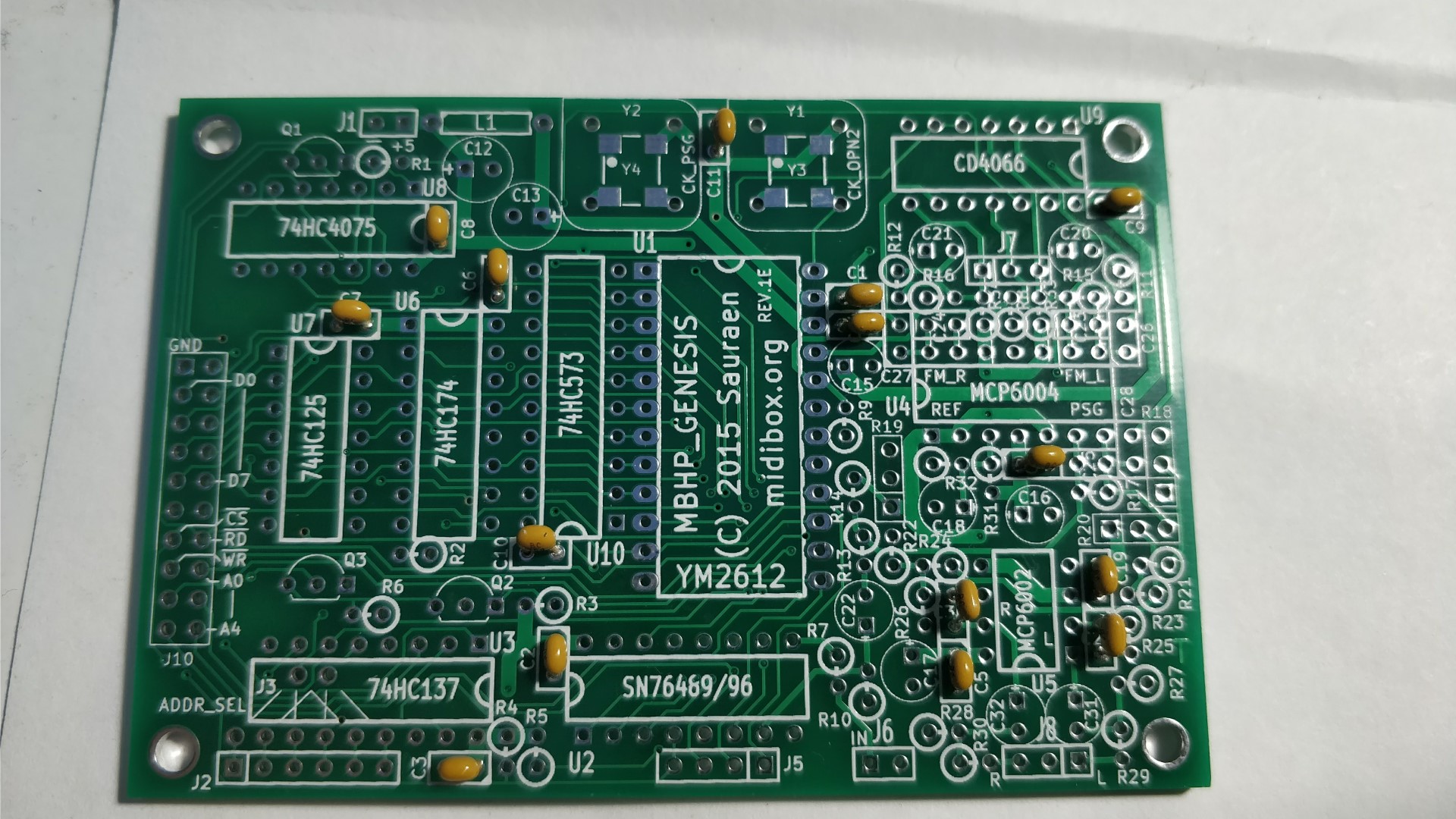
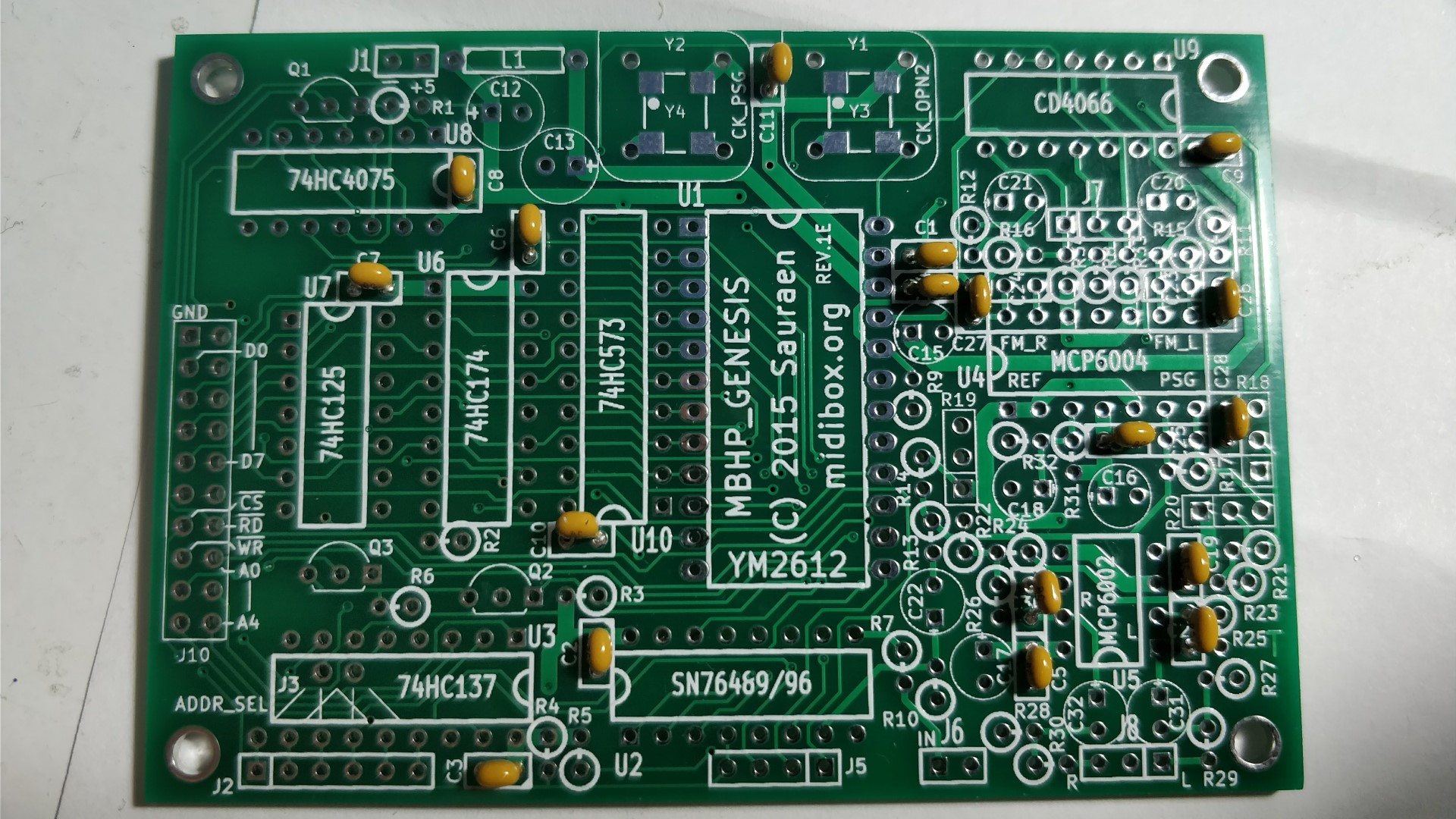
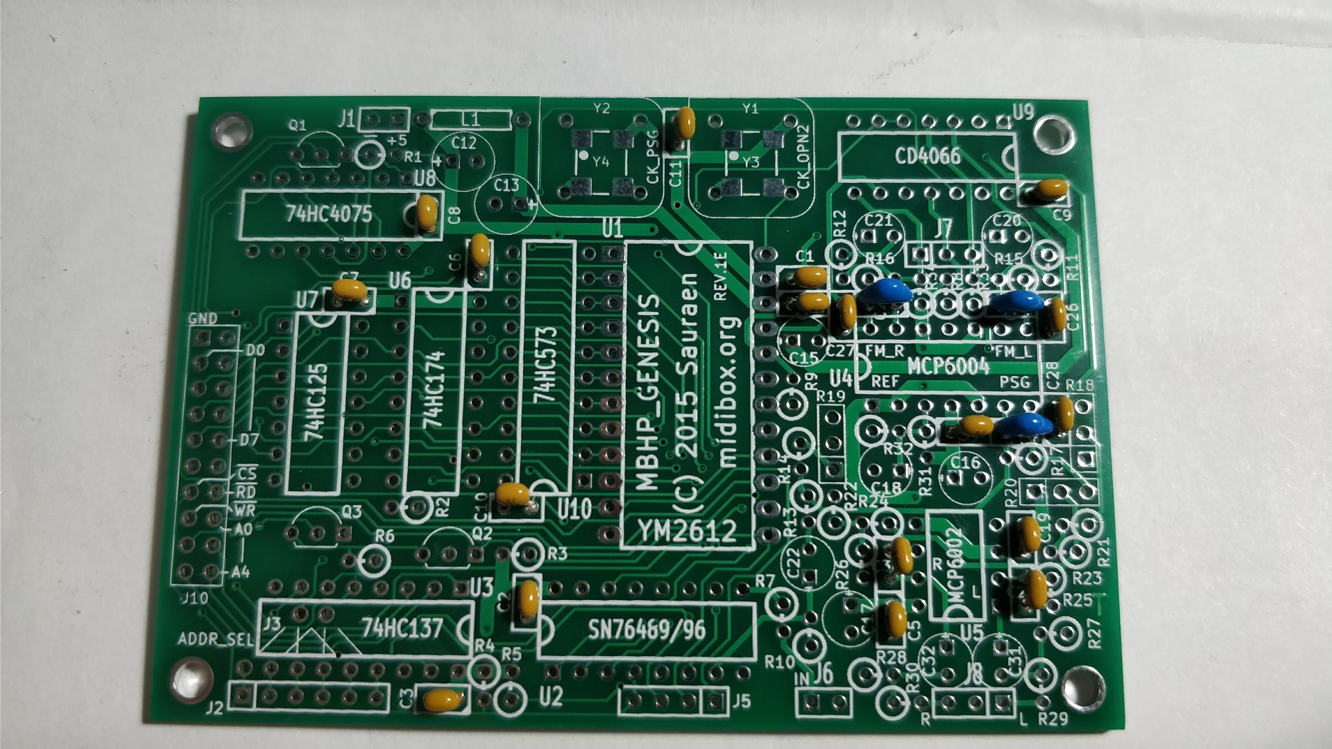
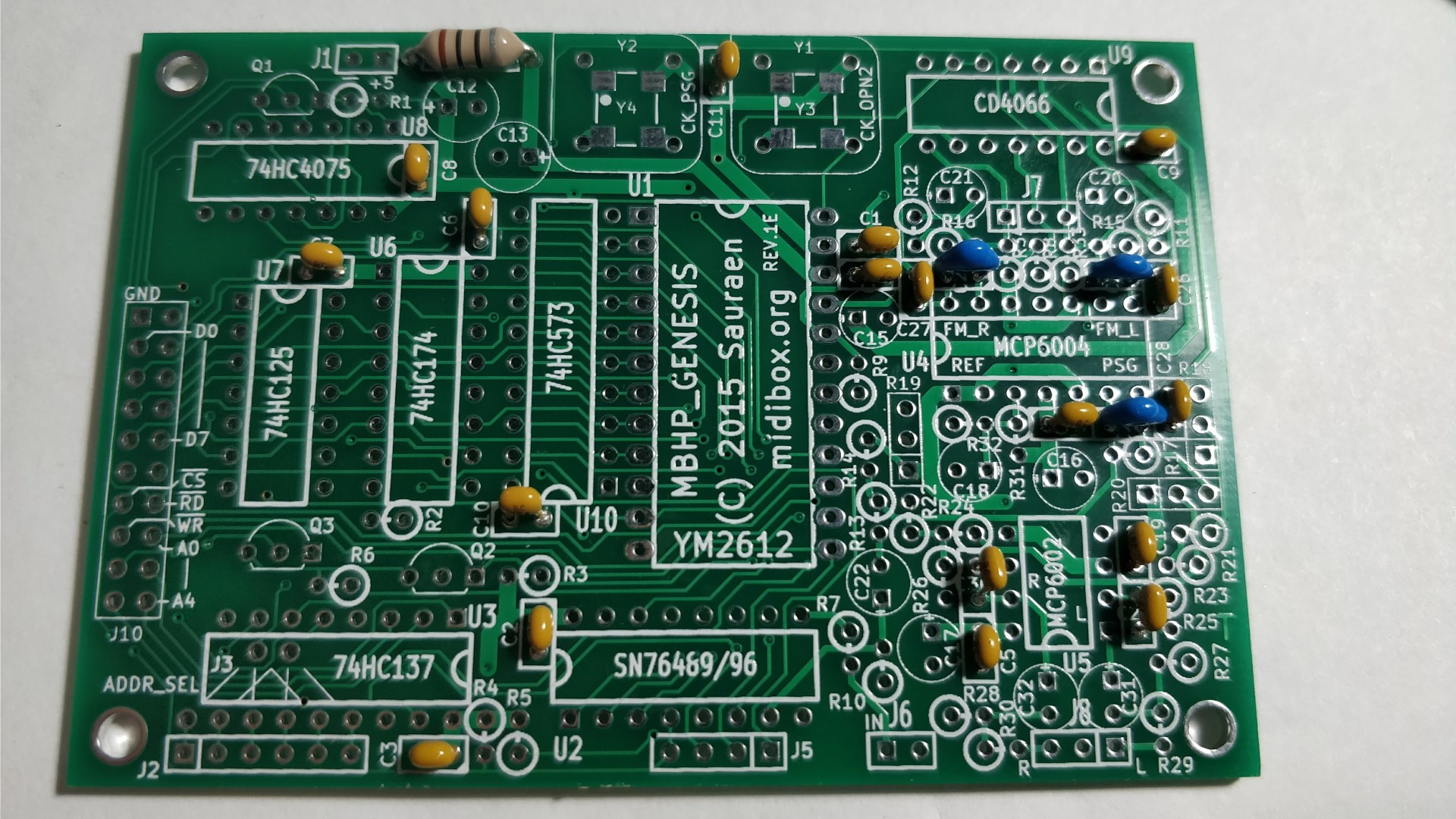
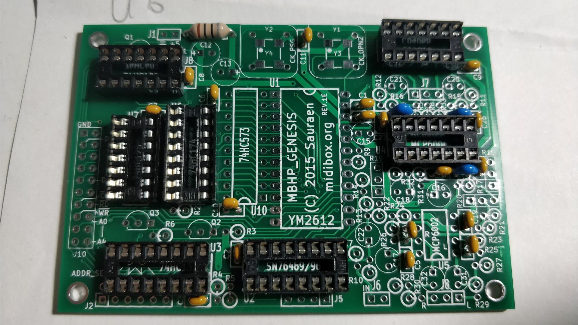
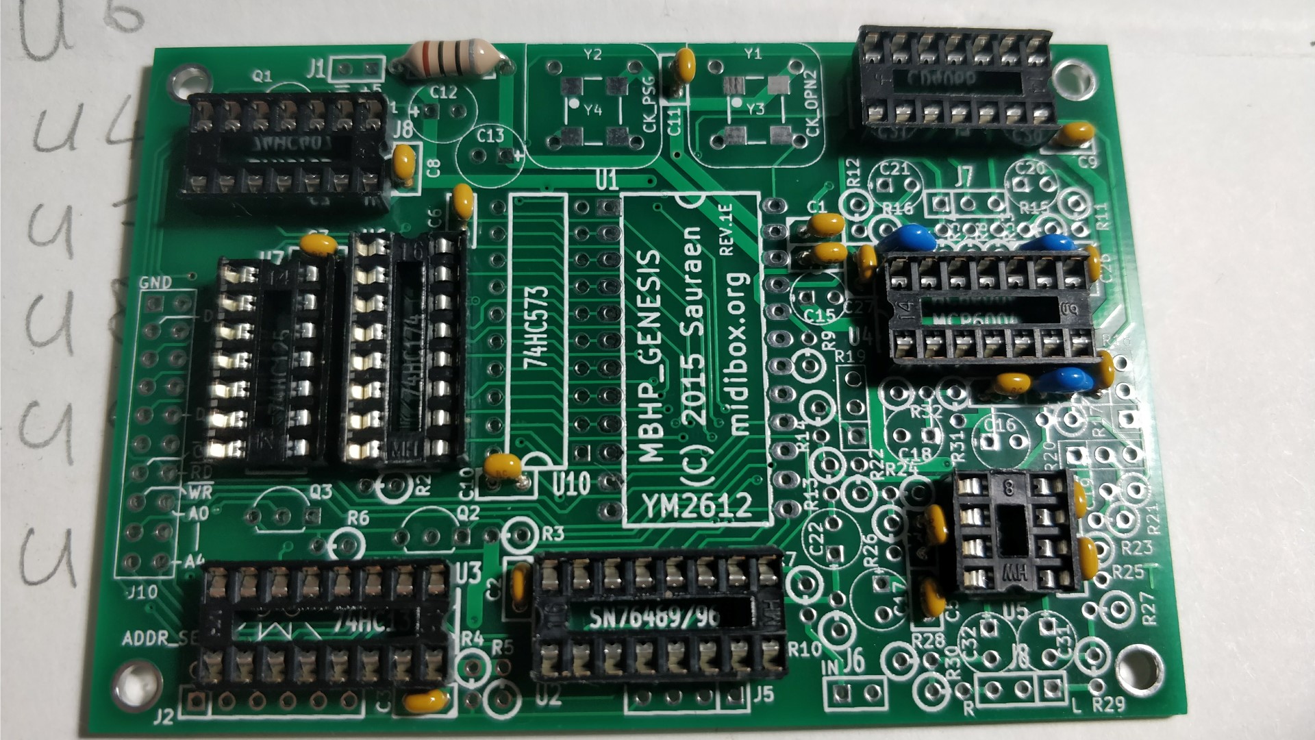
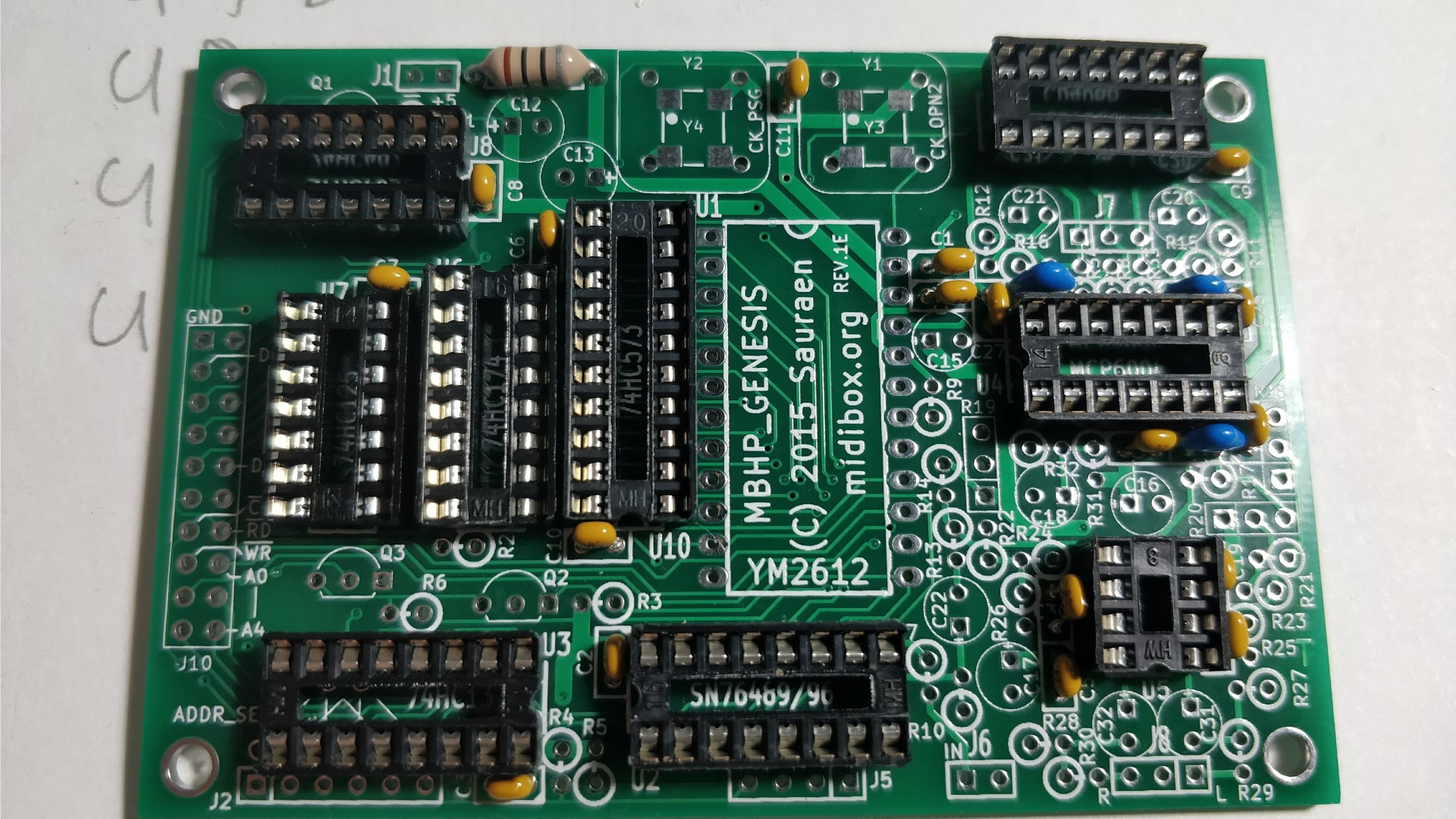
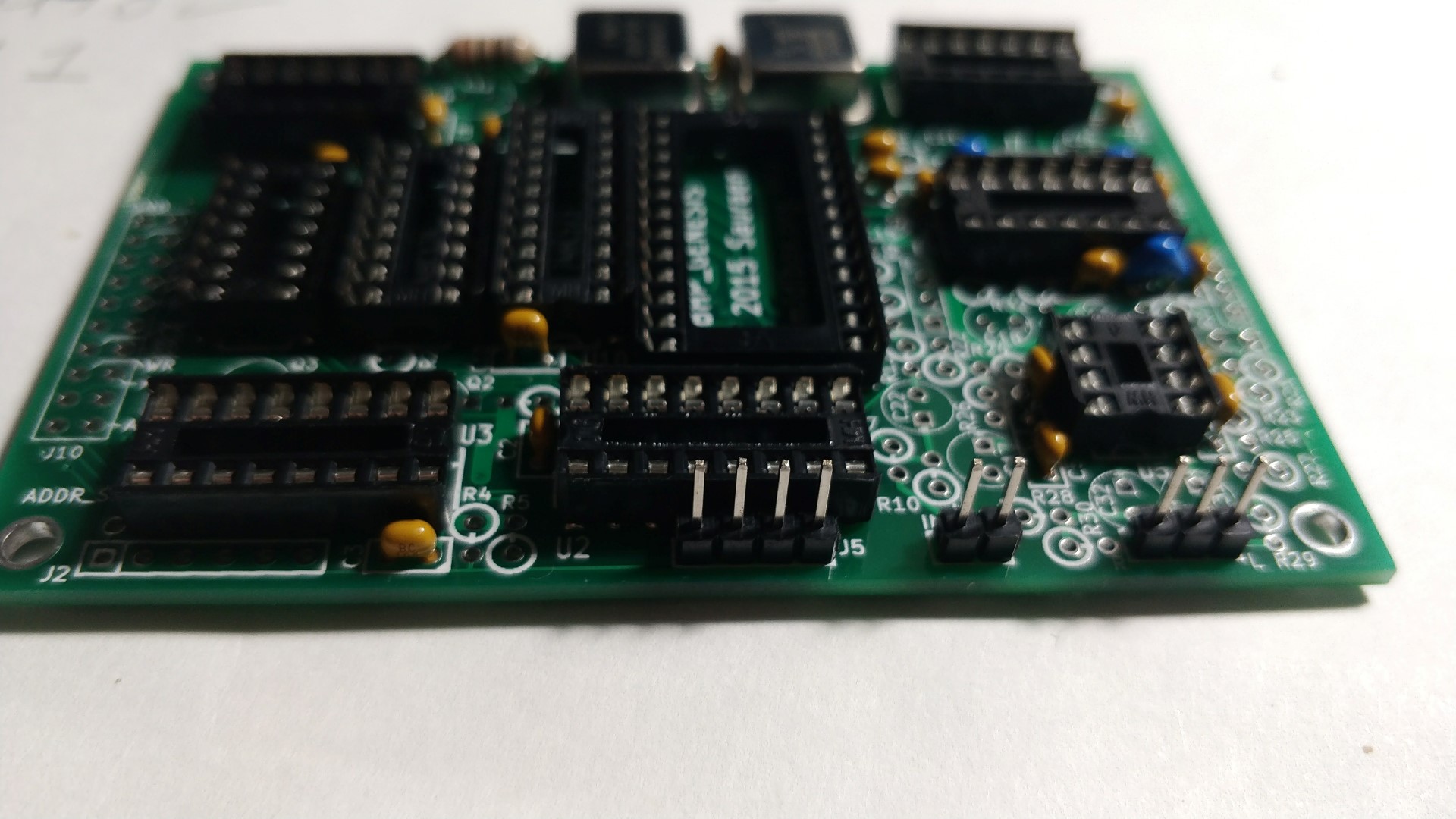
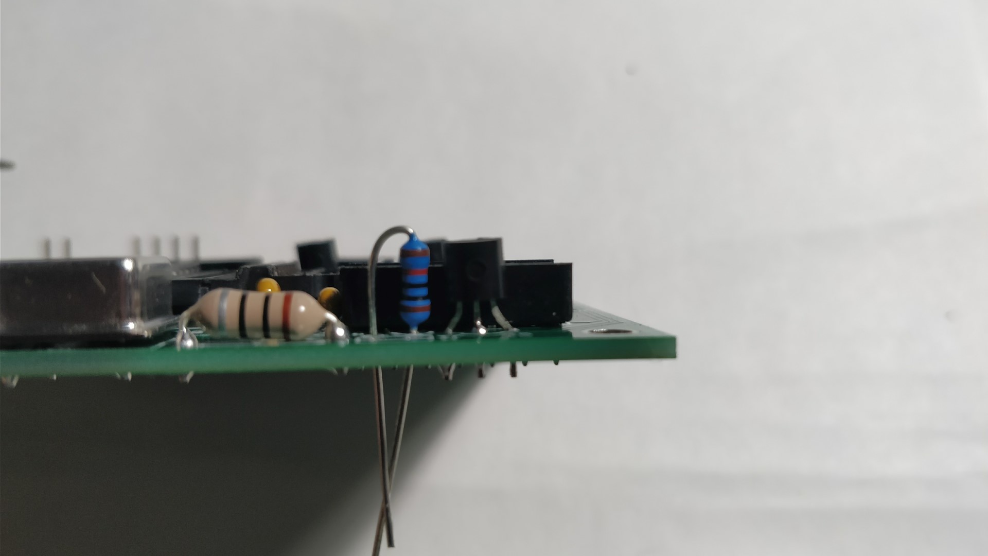
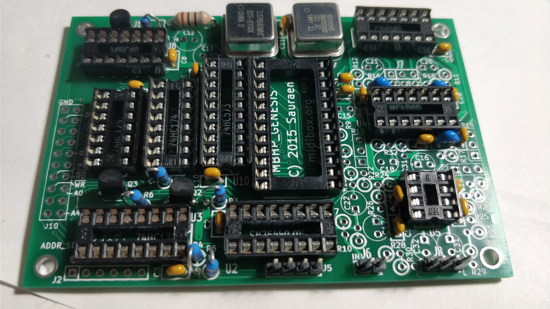
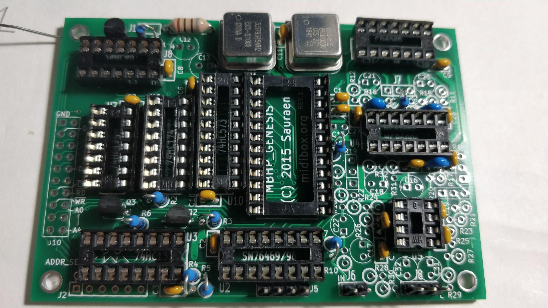
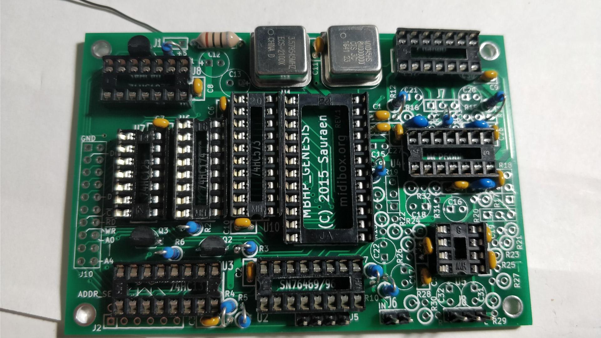
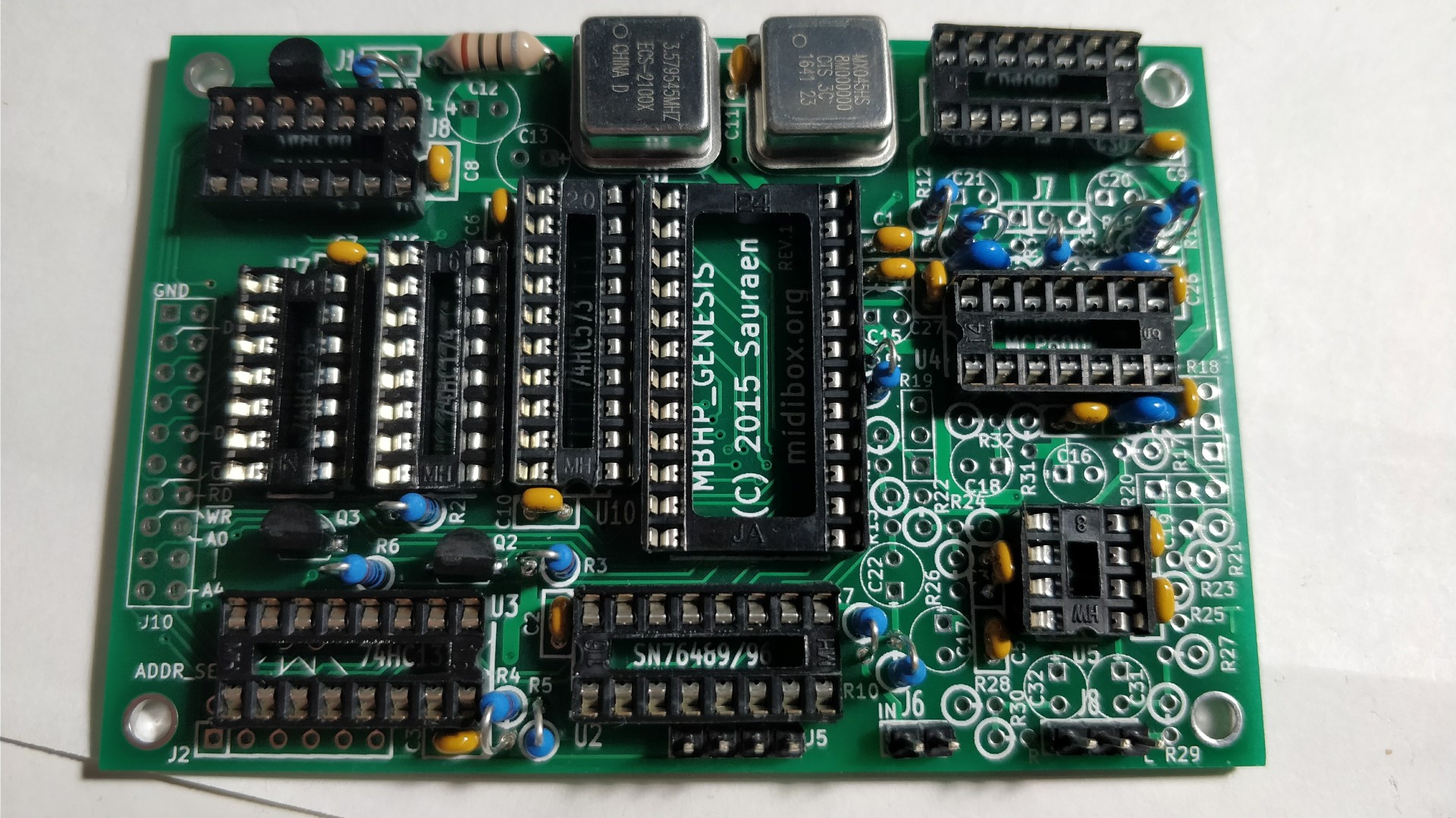
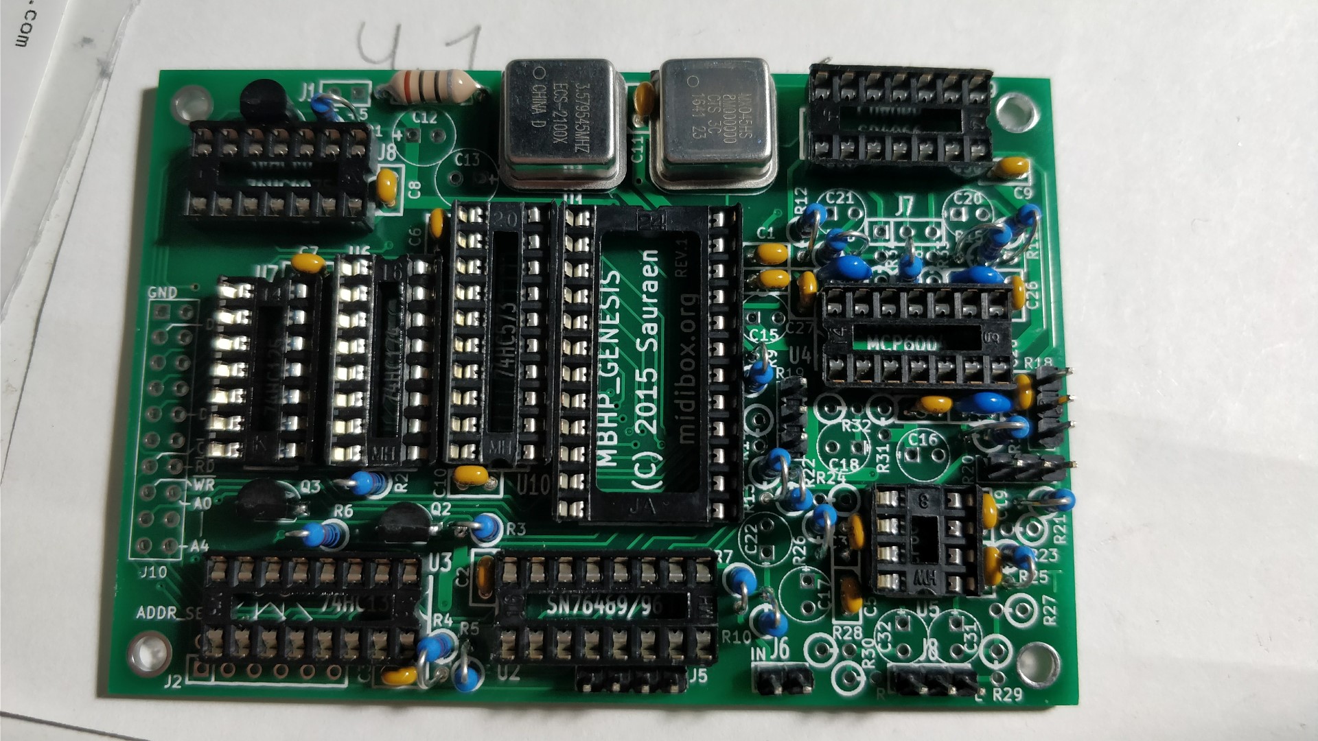
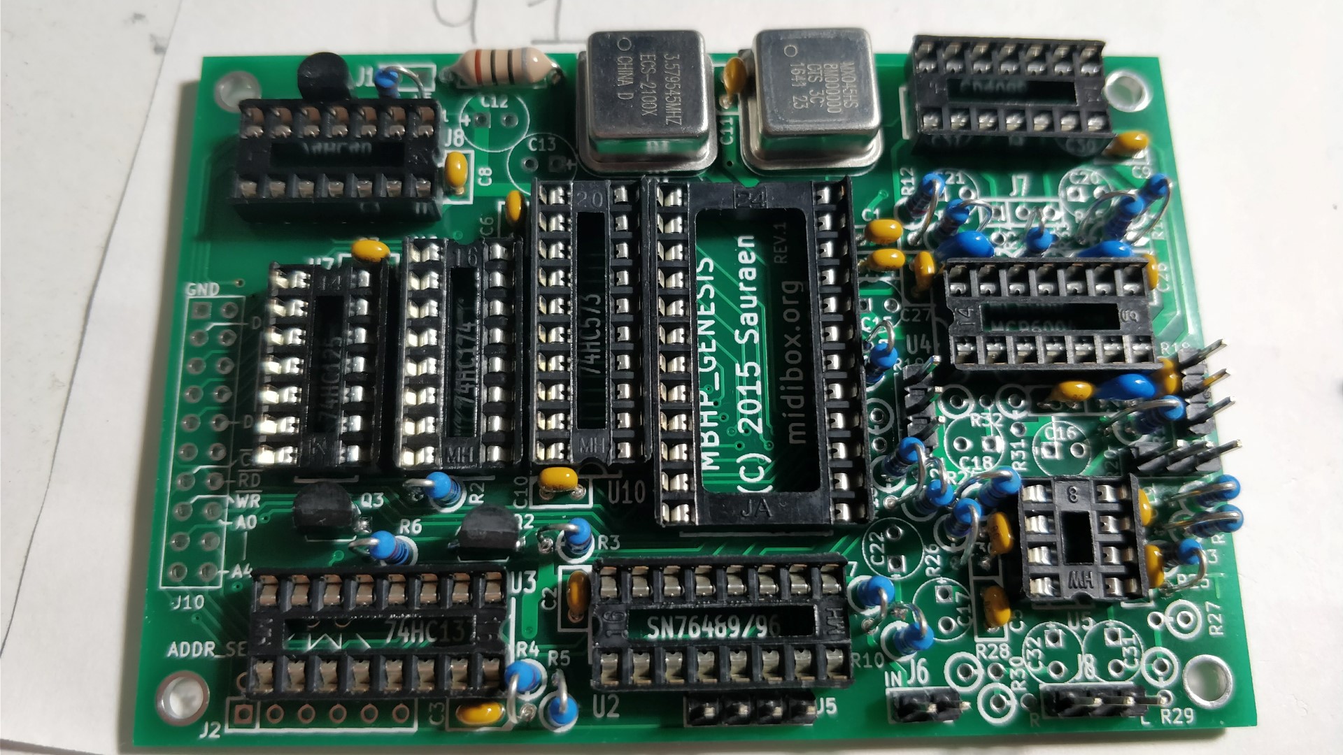
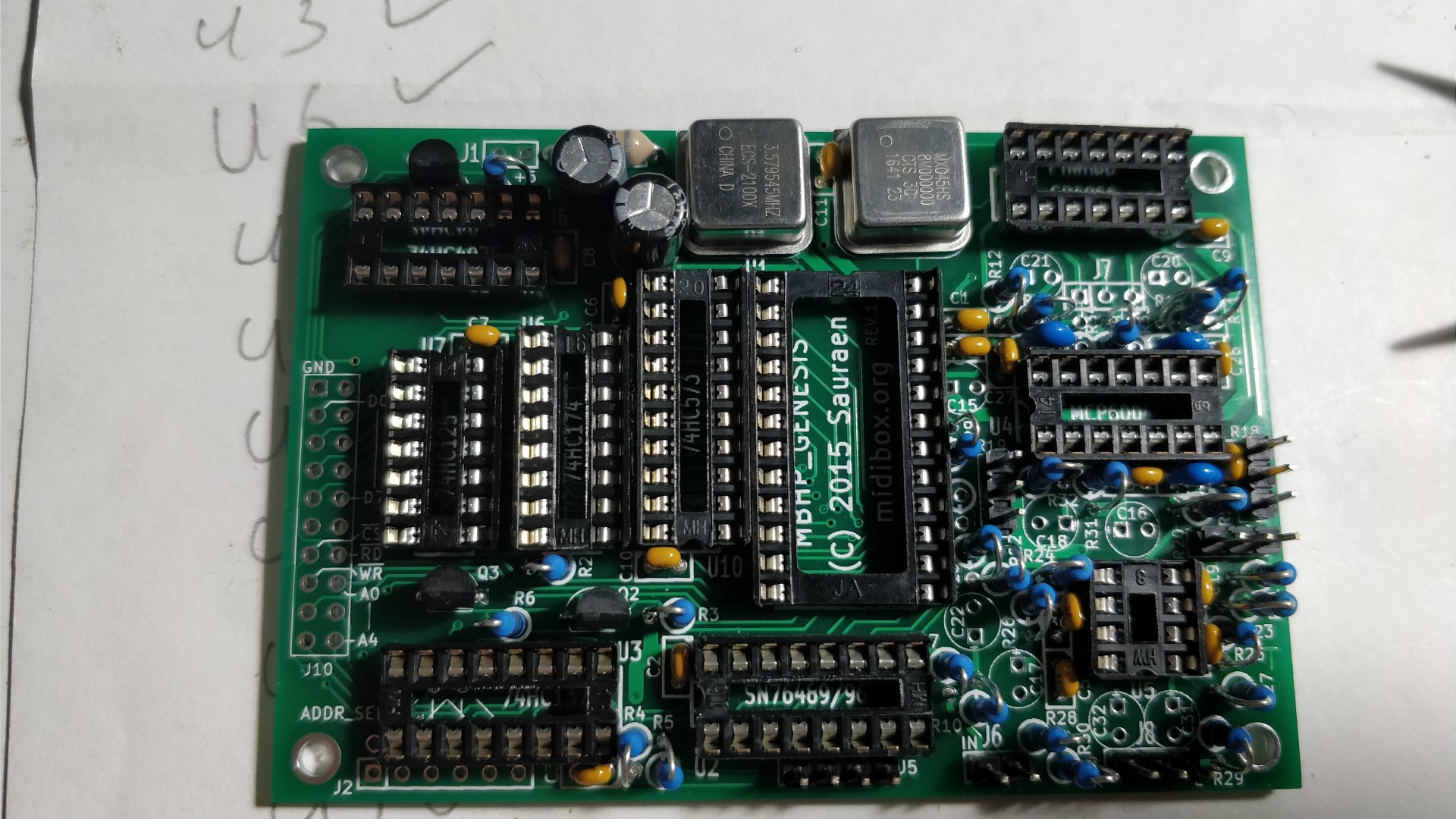
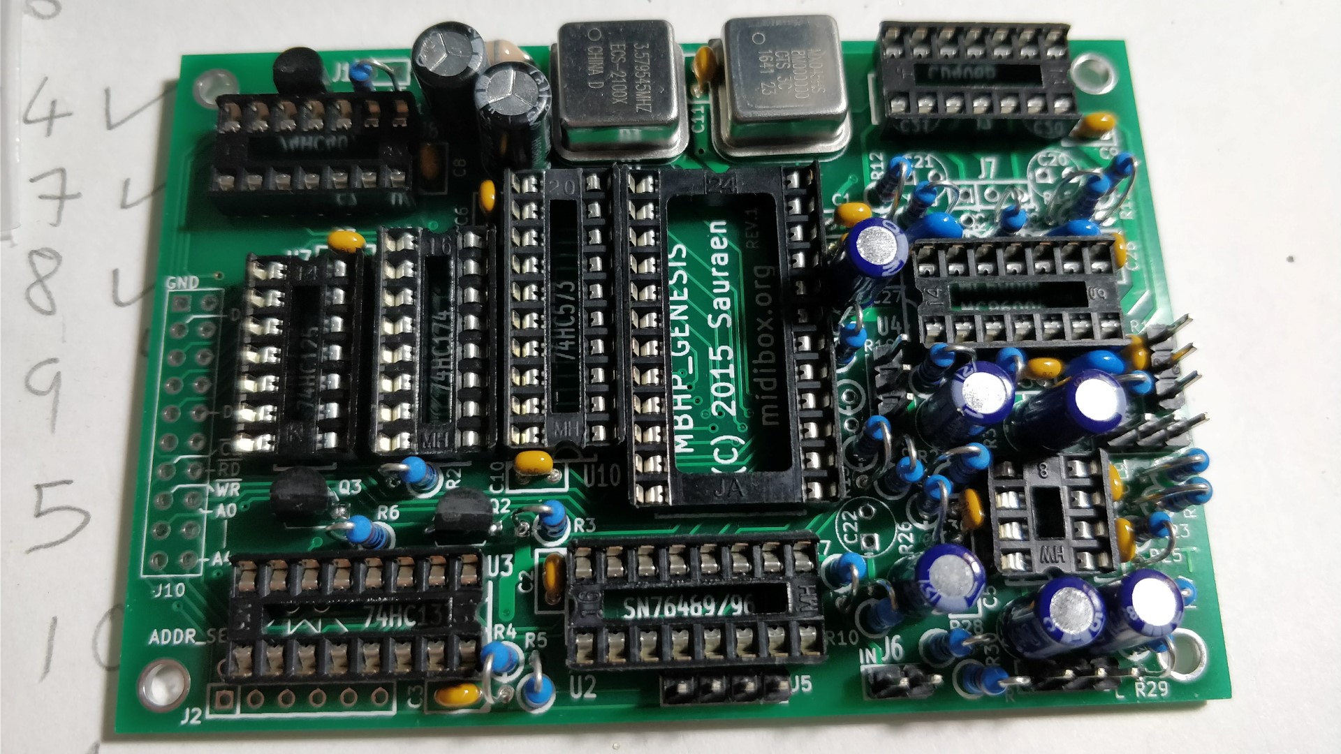
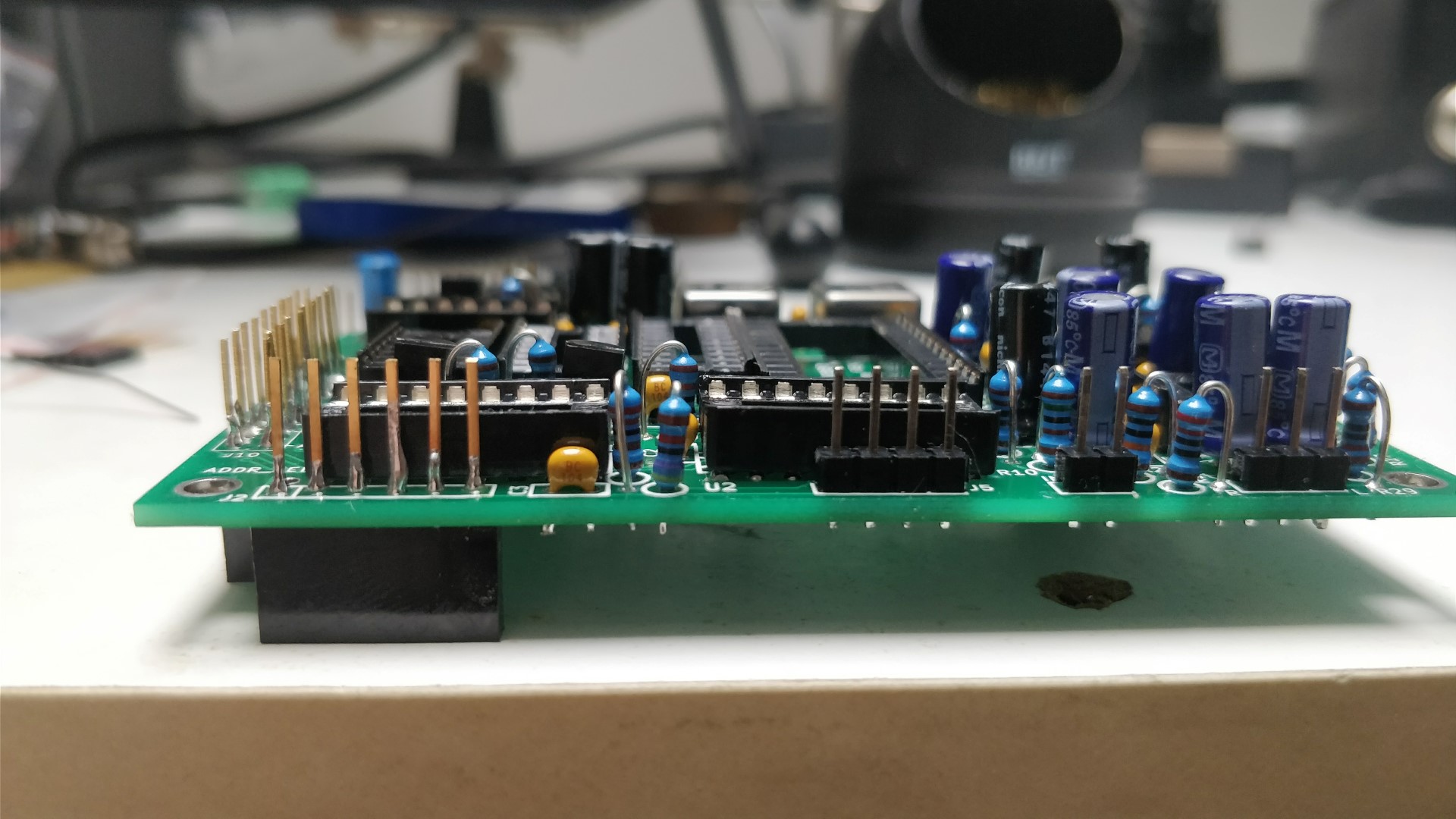
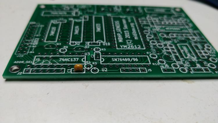
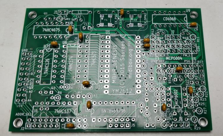
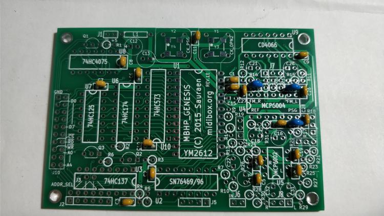
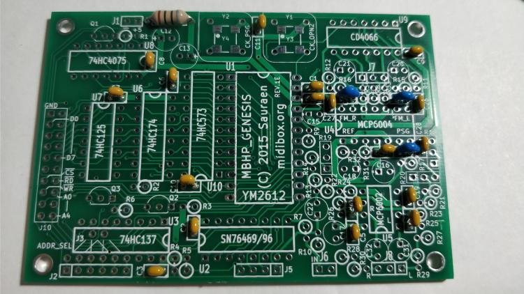
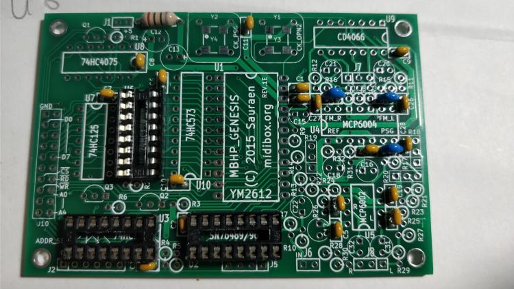
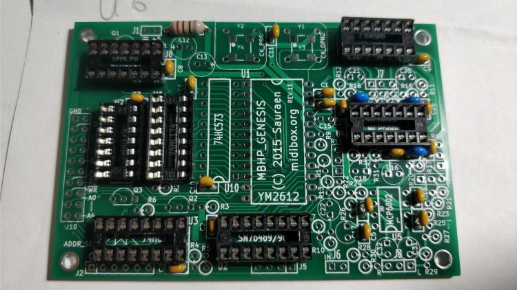
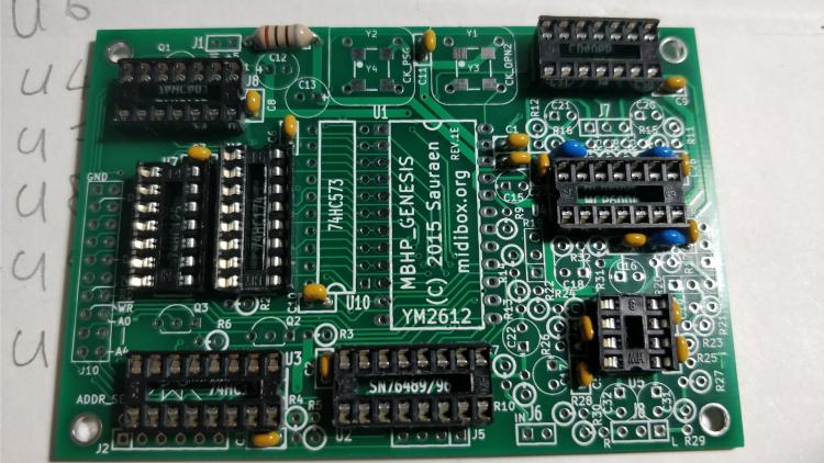
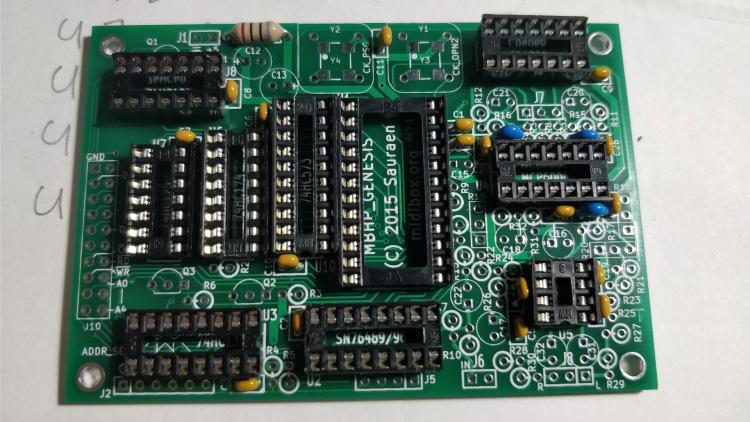
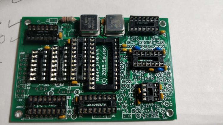
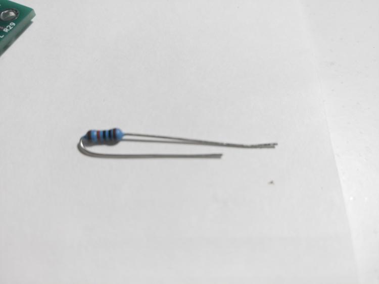
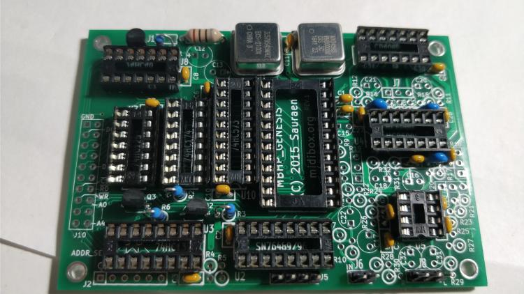
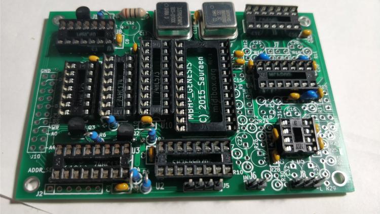
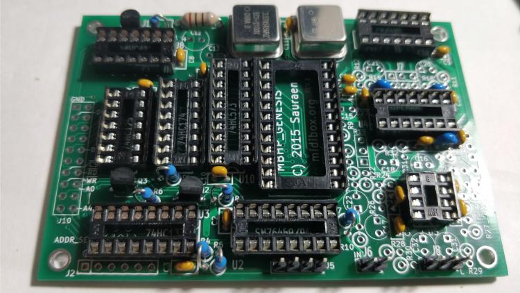
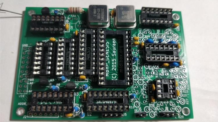
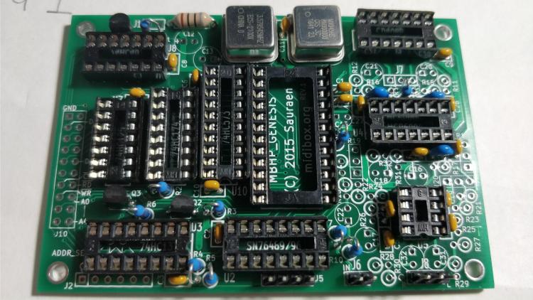
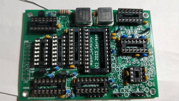
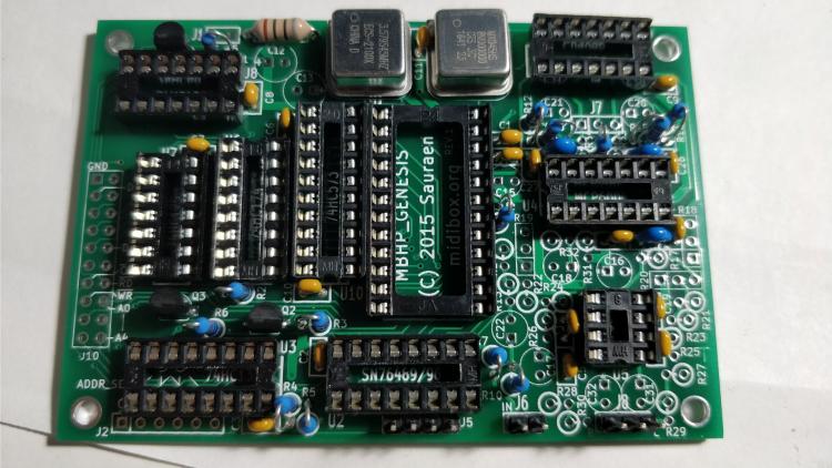
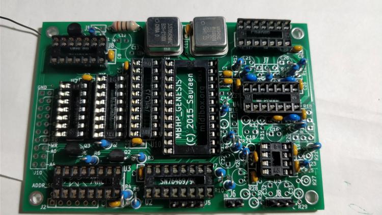
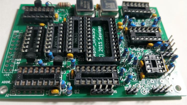
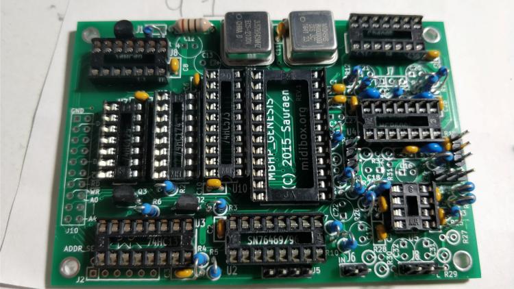
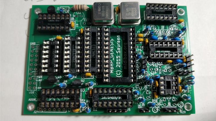
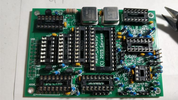
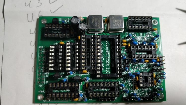
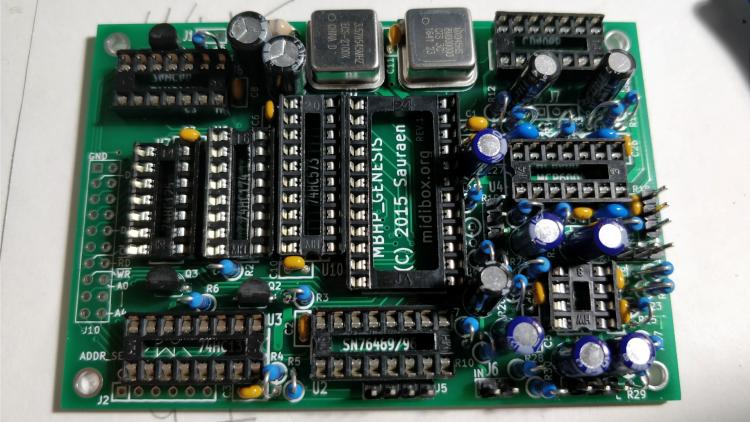
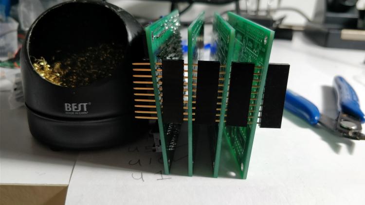
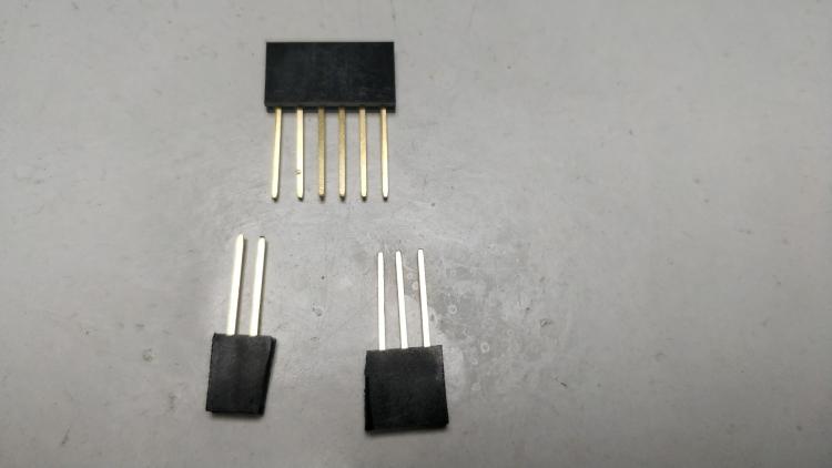
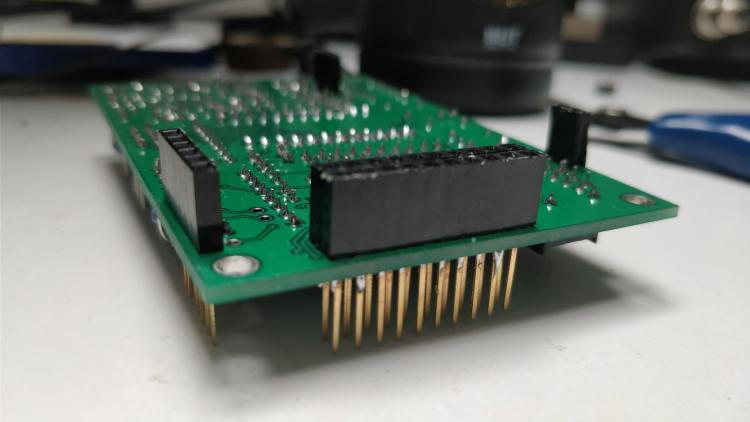
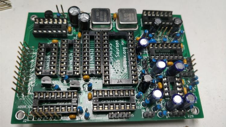
Step 8: Building the first Genesis Module. Since each board has a different address select configuration, we must read the wiki section: J3: ADDR_SEL "On board 1, stuff U3 and its bypass capacitor C3, but don't connect anything in J3." Start with by soldering Capacitor C3 0.1 uF. It helps to write down a list of the component refernces and tick them off as you go. Next populate the remainig 0.1uf capacitors C1-C11, C14, C19. Populate C29, C30 100 pF. Populate C26, C27, C28 1nf. Populate C23, C24, C25 180 pF. Mine were blue and slightly taller. Populate Inductor L1 10uH. Populate 16-pin 0.3” DIP IC sockets, [U2], [U3], [U6], take care for orientation Populate 14-pin 0.3“ DIP sockets [U4], [U7], [U8], [U9] Populate [U5] 8-pin 0.3” DIP socket Populate [U10] 20-pin 0.3“ DIP socket. Populate [U1] 24-pin 0.6“ DIP socket Populate Y1 (through hole) or Y3 (SMT) 7.67 MHz (or 8 MHz) oscillator depending on which OPN2 you will use. Populate Y2 (through hole) or Y4 (SMT) 3.58 MHz (or 4 MHz) oscillator at desired PSG frequency. Please take care of orientation, the corner of the crystal goes in the top left corner. Solder the SIL Headers for J5, J6, and J8. Solder Q1, Q2, Q3 small-signal N-channel MOSFET. See Sauraens note on the mosfets. Next up is the resistors, bend one lead 180 degrees so you can mount them vertically. The resistor itself should sit on top of the circle on the silkscreen, the lead bent lead will go through the other pad. Solder R1, R3 10k ohm Resistors. Solder R2, R6 1k. Solder R4 2.2k resistor. Solder R5 47k resistor Do not populate R7 if you are using a SN76489 as theres no audio input. Populate if you are using a SN76494/SN76496. ( I populated it by accident and removed it later.) Populate R8, R9 2.2k if you are using a YM2612, otherwise Do Not Populate. Populate R10 1.5k resistor. Populate R11, R12. Use 22k for YM2612, 47k for YM3438 Populate R15, R16. Use: 47k for YM2612, 10k for YM3438 Do not populate R14, R33, R34 Populate R13, R17, R21, R22, R25, R26 47k resistor R18/R19 are for the 10K Potentiometer. I soldered SIL Headers for these, otherwise you could solder the wires directly to the board if you wanted. R20 is the 10K potentiometer for the PSG. Again I used a SIL Header. Solder R23, R24 220k resistors. If you want a louder PSG, reduce the value. Solder R27, R28 100k resistors. Solder R29, R30 220 ohm resistors Solder R31, R32 10k 1% resistors. C12, C13 100 uF electrolytic capacitors. Solder C15, C16, C17, C18, C31, C32 10 uF electrolytic acpacitors. Solder C20, C21, C22 10 uF bipolar electrolytic capacitors. The Genesis modules need to be stacked using the stackable arduino headers with 15mm long pins. These headers with extra long headers can be hard to find, here they are on Aliexpress, play-zone, funduino. The top of the first board is facing left, with the pins sticking through, and the connectors will be flush against the bottom each board. For the bottom board you could use an SIL header with long pins You will solder the pins at the top side of each board. The following image shows PCB 1 on the left, PCB 2 to the right of PCB1, PCB3 to the right of PCB2 etc.. Please note that I used SIL headers instead of Aruduino headers for the headers on the bottom board PCB4, as you can see in the 2nd pic below: This is so that the black plastic won't be taking up unwanted space. I couldn't find 3 and 2 pin Ardunio headers so I cut up a 6 pin like so. Solder the ardunio headers at J1, J2, J7, J10 Next, trim the pins on the aurduino headers to the same height as the SIL headers, so the connectors for the wires plugging into them will sit flush.


 1 point