Leaderboard


Popular Content
Showing content with the highest reputation on 02/08/2019 in Posts
-
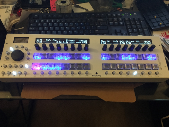
You rock! Had a few more hurdles to get over (bad I2C cable) but it's alive! Still have a couple things to finish before calling it complete - beat LED and I ran out of 10 pin connectors for the LineTX cable from LeMEC_R, but it's looking good! Thank you Andy, Peter, Bruno and the rest of the midibox community for all your patience, wisdom, and troubleshooting help! Thank you TK and Adrian for your efforts on this project as well! Can't wait to learn the ins and outs!
 2 points
 -
Yeah!!! which number is it? 7 or 8 maybe? cheers1 point
-
No worries, you provided good info (voltages and pictures) and had a decent attitude. If it works, we're very happy!1 point
-
Ah yep, set dout x 0|1 is the correct syntax. You could try the same on the second 595 chip, these would be dout 8--15. You've copied the same terminal data each time, but I assume you turned the correct outputs on and off. Note that pressing the up arrow on the computer keyboard will go through a history of the terminal commands.1 point
-
Thanks for the voltages, so the issue seems to be on the sink side of the matrix. As you're troubleshooting the _L board and the _R board works fine, it would seem as though the data is getting though correctly. Could you try the following commands in MIOS terminal: set dout d0 1 %turns first output on set dout d0 0 %turns first output off set dout d7 1 %turns eighth output on Here you manually set the pins, so this can rule out any errors from the software side. You can also try it with the .NGC loaded. When d0=1, the first four encoder switches should work when pressed. set d0=0, then d1=1 should allow the first four Matias switches. If the component values/types, cabling and soldering are all sound, then I'm beginning to suspect a dud IC. Could have been overheated or subject to static for example.1 point
-
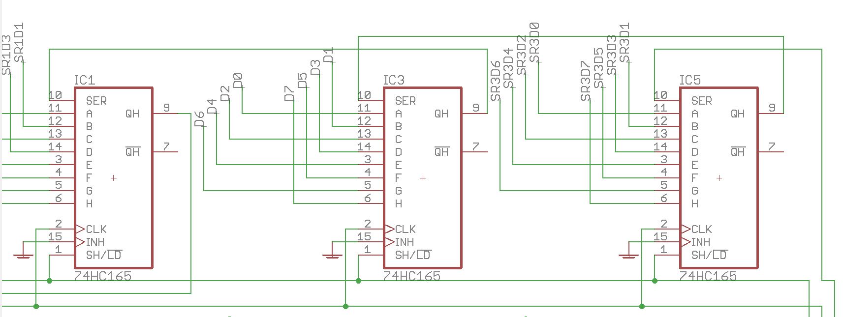
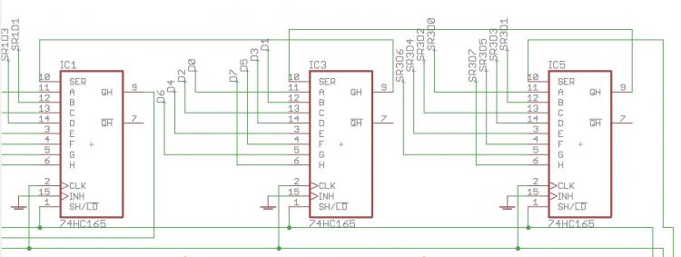
It might be interesting to solder down the superflux cathodes, then you could check if the problem is on the sink side or the DIN side. IC2 is the sink side of the matrix; you can see the sink part of the matrix here on the left. MIOS pulses each output in turn and this allows the switches to conduct to 0V when pressed (also lighting LEDs when that column of LEDs is on). This registers as a switch press in MIOS by the 165 inputs going low. IC3 is the DIN part of the matrix. D0-D7 represent the switch columns and there are eight per board from left to right. D0-D7 connect to the anodes of diodes located above Matias switches and beside MEC switches. As you have a functional lemec board, you can compare voltages on the two. The only difference with the _R board is that there are three extra shift registers (74HC595) at the start of the chain. Because you have some activity with encoders, the issue lies with either the DIN or sink side of the matrix. Do all encoders work? If so the SC, RC2 and SI lines are all fine. Check that the correct resistor networks are installed (also the orientation), check that you have +5V on all aforementioned 4148 diode anodes,
 1 point