C_04
-
Posts
68 -
Joined
-
Last visited
-
Days Won
4
Content Type
Profiles
Forums
Blogs
Gallery
Everything posted by C_04
-
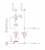
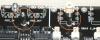
Hi Yesterday i already soldered missing few last parts. After fast/short tests i can say that everything works fine beside LCD backlight - i mean its still the same full bright, no matter that pot is turned left of right. Its not my mistake because ive compared schematics and they the same with pcb. Probably transistor has too big hfe. I found solution for such cases but unfortunately its too late because pcb is produced yet. I will make some cosmetic changes and thats it. Fortunately dimming is almost never used - i mean is set once, anyway i will check another resistors between transistor and pot (different values). In fact ive been mostly afraid about optocoupler which i bought somewhere from HK or China but they work excellent. Maybe i could provide pcbs for these two persons but i would like to know that you need complete pcbs set with control board and this small for connectors? As attachment you may find my solution for dimming. Works every time no matter hfe you have, may be problematic that regulation is only 1/4 of pot scale but at least still is.
-
Hi Today ive received package. Thanks a lot:) Regards and stay tuned C_04
-
Hi nILS Do you planing to release next batch? Regards
-
Hi You cant have sammich:) Difference is: partly SMT, much simpler, 8 banks memory, dont have these led matrix or even output registers (595 on control brd), boards are designed by me and idea here was to be used in different setups as i said: desktop, rack, extended desktop etc. To me sounds the same so no more differences. Should be cheaper if that matter. Regards C_04
-
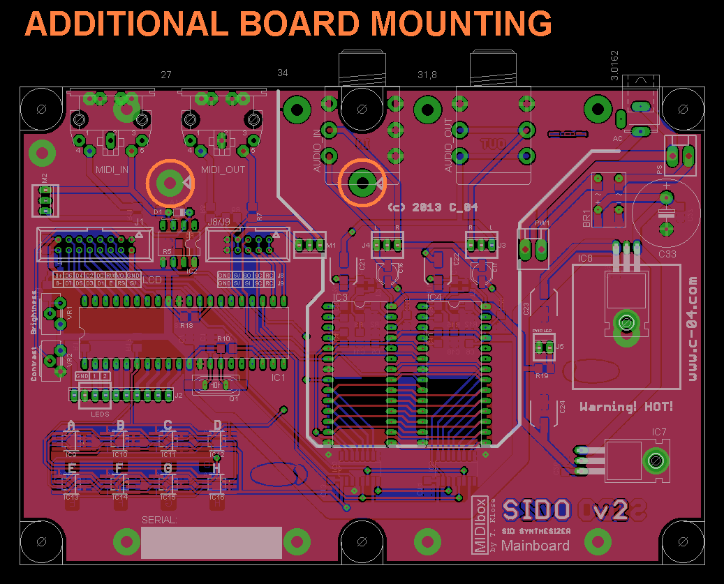
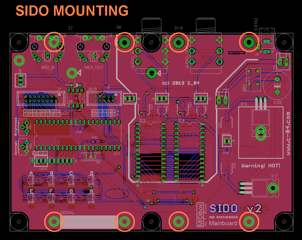
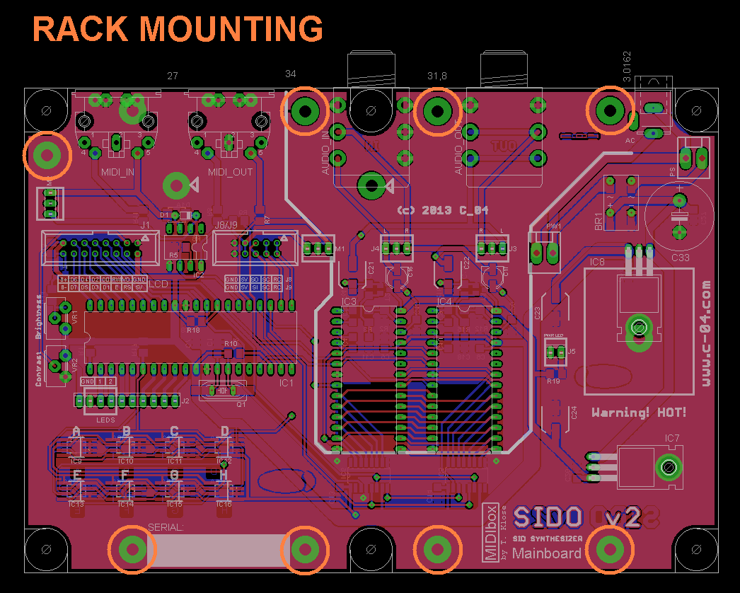
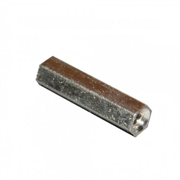
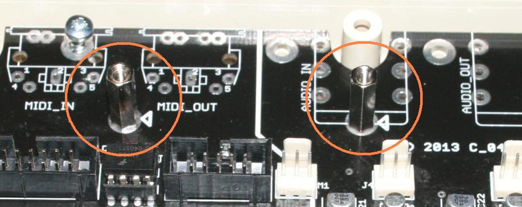
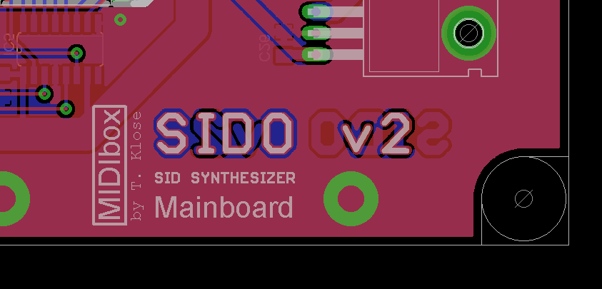
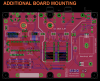
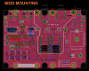
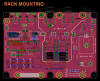
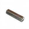
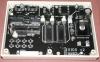
ilmenator - MIOS is exactly the same only setup firmware is little different and only with exactly one control board yet. You may if you wish to use sammichSID control board and then you have to upload setup firmware for sammichSID. I think it explains to you what i thought saying "software". That screw and few other places as i said before can be used in other versions of SIDO. If you assembling this SIDO here, you will need distance bolts (one of attachements). Additional board must be about 20mm higher than mainboard. For example if you wanna build SIDO RACK - then you dont need this special additional board (it lift up/move up connectors) - you just mount all this pcb to back panel of rack + if possible to floor/bottom plate of rack enclosure. Here also another control board will be necessary and of course i think setup firmware. Sido has only one control encoder but in RACK you can use as many as you have place there. Im adding attachments here to explain better. Orange circles shows where and when you have to use screws. :smile: Cheers
-
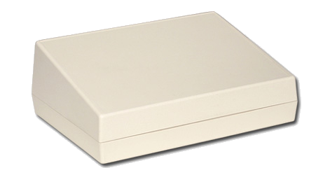
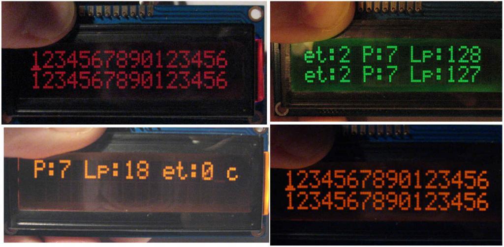
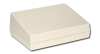
Hi Im attaching another pics from work progress. This picture with pcb in bottom of enclosure looks little dusty but i did polished corners to fit it easily. I forgot to point that i want milling;) Also as you can see SIDO v2 soldermask is moved down. These and a lot different problems we found when sending gerbers from EAGLE. It has some problems with fonts. Eagle change them when exporting to another one type of font and then looks really ugly. This board can operate with 3 types of memory: TSSOP8 and SSO8/SOIC8 both EIAJ and JEDEC. Sorry guys I have ordered only this one pcb for testing because i wasnt sure that everything is ok. So i was right - nothing is ok hehehehe. I would prefer if it will be in sale to sell assembled because i can test then whole device + upload software. Especially it must be dedicated software - if comparing to sammichSID control board has swapped connections to registers. Im not saying that bare boards will impossible to order - just i would be sure that future user has working synthesizer - not tons of problems. This one pcb cost me a lot because what they call it "i started manufacturing process". Fortunately they said that they will fix these all mistakes free of charge. Ahhh i forgot to say that as you can see there not much to soldering:) Cheers C_04 P. S. Ive attached some documents for enclosures. P. S. 2 Im plannig to use this red negative LCD but also im thinking about orange. Depends which will fit better to other part of design. I have so many brown switches and here orange display could be better choice... but this red looks so sexy:) P. S. 3 I did some fast calculations and at 10 boards each of them may cost about 25 EUR but if 100 pcbs ordered each of them could be about 12 EUR. Its just my calculation not pcb manufacturer and im not sure it will exatly like that. Note that there will be needed another two much cheaper boards (control + connectors). Serpac 17S.pdf

-
smashtv - yes i know license: 10 units no more than 1500 eur. Ive read Thorsten topics about that. But right now im prototyping boards so its long way and i sold nothing. Ive send him also some question about commercial license if i even finish this version of Sido. I should maybe ask in the Sale Request but its i think little too early. tomtiki - that was the idea to use the same board as desktop and rack module in even different versions. Also thats why boards are separated (control and mainboard). Mainboard is exactly fitted to Serpac enclosure. At this moment i have a lot problems... for example control board cant be easily mounted, boards need some corrections, switches are hard to get (its reason to separate control board too) etc etc. As i said previously i would like - if i will sell them - to sell partly assembled because SMT. Im soldering 0805 parts to 1206 pads just because ive bought better quality parts: Murata, Panasonic etc. Electrolytics are smaller too but it doesnt matter. Regards C_04
-
Hi If i may i will pick them all. Especially these SRAMs 4MBit are what im looking for. Also often i use 27C256 and 27C512. 27C256 will be used in my druum module sth like TR909 im finishing now boards designing. Its my biggest project and it took me a lot of time. In fact i found some pics in internet of somebodys TR909 replica so it helps me a lot in drawing. But im thinking that there toms and clap + cowbell could be also in eproms because they not controllable (even pitch is constant). This SRAM K6T4008C1B is not pin compatible with another SRAM i need but if there 20 pcs i will redesign pcb even for stereo;) So how to contact You? Maybe via PM? Regards C_04 Greg
-
Hi Thanks for reply. I may pick them all:). I thought You will send them in one small package. Of course im talking about private use. I have old DYNACORD P20 its a drum module. Ive designed cartridge and they have replaceable (or however) sockets for eeproms unfortunately right now only for 2764 but ill add there switches and will be possible to choose exact drum sound. So in 27512 there may be 64 voices but there will be necessary to use 2 binary switches. Its little complicate to reload single eprom UV erasable and thats why i use them a lot:). This module sounds '80s because its 8 bit machine 24kHz sampling frequency - hihats mostly are ugly or i should re-EQ them before use. Depends what SRAM you have - i would like to build a freaky 8 bit sampler. I also have idea to build something i called "stereoizer" but when ive tryied to simulate it - was closer to something like chorus. Basically its white noise slowed down to 20-100Hz (user may set it) which is controlling noise gate for separate 2 channels. Next step is a funny compressor with responses in eproms. Its for todays music to make this pumping sound but more controllable maybe like ADSR in synths. Envelopes will be like waveforms. A lot ideas but not so many ICs.:) Regards
-
Hi How much would cost me shipping to Poland? I would like to get them (eproms) but im not sure its worth it;) I need different ROM/RAM's for my devices. Now im using these old ones from motherboards - i buy them relatively cheap. But free is always better than that. Cheers C_04
-
Thanks. Im really sorry for my mistake and already ive improved that but dont know its not too late for pcb machining. Ill check. << WAS NOT:)
-
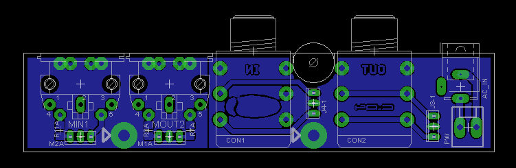
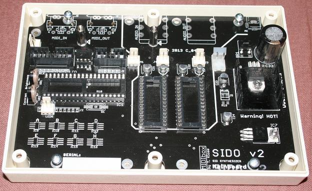
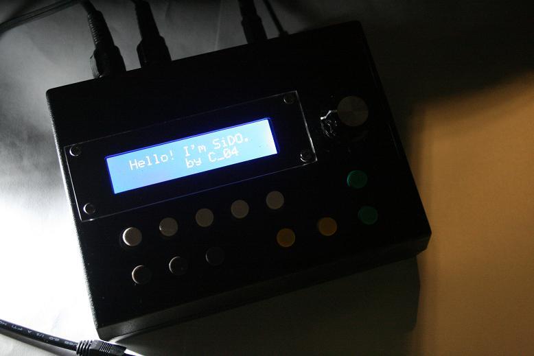
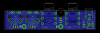
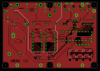
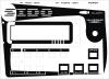
Hi Ive tried to build my own SID synth and i did it successfully. That was single SID prototype and now i redesigned all pcbs - in fact some of them need some job because i had new ideas (CC and AutoWrite leds on front panel). It will be one 2 color led with priority where AW has higher than CC. Im sure that many of you would like to have SID synths but you are curious of your ability in soldering - thats why im thinking of selling half assembled boards, especially they partly SMT. Pcbs are double sided with many possibilities in parts there used or even building custom SIDO's. Ive designed mainboard to use with Serpac enclosures (im not sure they send me some samples that i could build exact prototype). To use this mainboard within this enclosure will be necessary small another pcb to move up rear panel connectors. There will be also another board - control board: 12 buttons and 1 encoder with button. Only mainboard is double sided, another boards single sided. Now im looking for some switches widely available and of course cheap. Ill inform whats done. One thing what i need is blessing from Thorsten:) So im attaching here picture of mainboard. Regards C_04


-
Hi Maybe little late but...: http://www.analogx.com/contents/download/Audio/sayit/Freeware.htm Regards C_04
-
Another thing is that previously i had the same problems and everything works perfectly only if i remove it from enclosure. Thats ridiculous but strange things happen. And You probably right - these cheap Chinese connectors... ehhh - i have probably the same thing in my 1176 which is lying on the floor somewhere because no compression;) Thats ridiculous multiplication: compressor which not compress. Now i think that i would know what i know now - i would design these boards much simpler without any jumpers. Now i have 3 and one side PCBs. So in fact its simplified sammichSID just maybe for try how it sounds, how it works and every other "how". Also cheap and easier for any "soldering-dummy". Problem may be SMT parts but its nothing scary. Best Regards and lot lot thanks. C_04
-
Connections - checked there is not any swap - in fact its impossible because i have soldered DINs to these small plugs with direction lock. So i cant put it wrong side. I have working system, memory card was correctly formatted and just for fun i soldered now only 4 ICs numbers 1,2,7,8 (7,8 are in sockets as i said previously). Even that i've uploaded few patches in few banks just for try it works. After power-on nothing happen. But after try to sending HEX it only reboot SiDO and nothing... unable to connect core (or wahtever its there written). I wanted just upload this new HEX with correct settings for my setup. Yeah voltages... i will check them. Regards Measured voltages = 5,01V but between midi out = 0V. Between any of pins midi out to gnd - 5,01V Looks ok You will not belive me... it works again. I have no idea why it happens.
-
No, core part is not changed yet. Firstly i designed new panel board with registers, buttons etc (partly in SMT - only caps and switches are not SMT). Second board is rather card - memory card. It has 8 chips which are 6 SMT and 2 DIP (No.7 and 8 [ensemble]) - it helps when i want fast remove bank because they both are mounted in sockets. Funny thing is that i already programmed uC previously. Maybe reason is that there now conneted these 2 boards+display. Anyway it would be little silly when uploading works only in naked core board. All Best
-
Hi Thank You very much - now it works but unfortunately my SiDO wont respond when im trying to connect via MIOS STUDIO. I have no idea whats wrong i measured all this midi path from midi cable to processor... i used 2 different midi interfaces (MIDEX 3 and ESI 8) - no success. I programmed another bootloader into different uC and nothing. One side communication works because i can upload patches to SiDO but i cant download them to Win XP. I tried it into two different PCs. Still nothing. So now i have HEX file which cant be uploaded - thats irony;) Regards C_04 P.S. Configuring hex file was easier than i expected!!! P.S.2. Whats the specials? > ;; if != 0, special variations for sammichSID hardware will be selected
-
Hi I've tried to compile new hex file for my sid synth called SiDO. Its some kind variation of sammichSID. I dont use any led, i did made my own front panel design and also PCB for this. Problem is that assignment of buttons its not accurate for my needs. I would prefer to move "menu buttton" under encoder push button and also few other mods like change encoder type (probably detended3). The problem is only what i get are errors: src/main.inc :25: Warning [209] Missing quote src/main.inc :25: Error [103] Syntax error include/asm/macros.h :188: Error [113] Symbol not previously defined <MBSID_VERSION_STR> *** [setup_6581.hex] Error 1 Im compiling usising this tutorial: http://www.midibox.org/dokuwiki/windows_toolchain_quickstart Would be some of You so kind and tell me how to do this or would do this for me? Im not sure thats everything is set correct - so i would like do it by myself also because i would like to make few other mods in future. There attached file with setup file. Regards C_04 setup_sido_sid.asm