C_04
-
Posts
68 -
Joined
-
Last visited
-
Days Won
4
Content Type
Profiles
Forums
Blogs
Gallery
Everything posted by C_04
-
These blue displays are probably the best visible lcds. But i still prefer red:) Orange are cool too. But the best to me are these VFD used e.g. ENSONIQ TS10/TS12 synths. Unfortunately they only green. Devices with them inside looks stylish and expensive. In one word - great. I see few of them on my local auction portal but the price... ~29 EUR :(
-
I have the same but negative red < im big fan of reds;). I made special adapter for simpler interconnections if they 1:1. Just what i need is to solder IDC sockets and this adapter itself to lcd. Interconnection are via ribbon cable with squeezed plugs. All job is fast and im 100% sure. Cheers:)
-
If everythings fine now then is great news:) Anyway just for info: ive bought blue 1602 displays on ebay and they cost me 2$ each with shipping. Unbelivable:) Ive bought 8 of them and i have no idea for what;) Cheers and youre welcome
-
Im not sure about 8 bit, there may be necessary to upload new setup with "turned on" that option. Its only my speculation because i never did it in MBSID. So leave it now as is. If you have this second project ready waiting only for lcd then use this one you have - also it will tell you about its condition. Once in the past ive read about flickering in 4 bit mode and someone changed it to 8 bit with success. These time intervals: 10 mins.. 20 mins says its probably reason with current flow. Sometime "cold solder points" (as we call them here) produce that interresting visual effects;) Reasons for that are: bad tin, too low temperature of soldering iron, dirty legs/pads etc. Check all this path around lcd connector points. Another MBSID functions work properly when display is flickering? Maybe problematic place is a distant place;) Maybe you have inefficient power supply or maybe 7805 is oscillating... many possibilities here.
-
Double check then lcd interconnections pin to pin especially they not 1:1 compatible <easy way for trouble. When you will be sure tthat here is everything fine check maybe core pcb. Problem may be with PIC socket if you have. If you have possibility check lcd in another device or another lcd with core. You can use almost anyone 1602, 2002, 4002, 2004 - without uprgrading softare. Just connect - they will only not shows properly if not the same as you had previously. I check lcds that way everytime - connecting them to working device in place of display that this device had/normaly have. P.S. Bad soldering tin often makes bad soldering points;)
-
Once ive had similar problem - also my lcd was flickering. Reason for that were shorts at lcd connector. You may make a test: measure all points when lcd is working properly and do the same when is flickering. You can also have broken/damaged lcd. But i strongly advice you to check soldering points first. Cheers
-
Hi There are few possibilities to check: - weak quality pot - change that part - bad solder points - resolder again - invisible shorts - observe pcb - other e.g. : your lcd likes too much power Cheers C_04
-
Hi It was a long piece of time:) Im still working of the same problem. Maybe it exist only into my head but heat problem is a really big problem from my point of view. So im checking another solutions like diodes in series with 7809 and 7805. It reduced heat a lot. But my last idea is: it could be so beautiful just to connect this synth directly to the wall socket... I ordered that switching power supply for tests. It works on TNY266 IC. We will see what happen:) Problematic will be to isolate high and dangerous voltages from places anyone can touch even if SIDO is open. Cheers C_04
-
Sorry for my late reply. Anyway HI:) I cant see brightly whats inside but i see some wires which may be these you need to connect LCD. These boards looks like custom - made. So i cant say anymore. If you need/want to have control panel you will need also declare what is a must have to you. As you can see in my topic "sido - simpler than sammich" i decided that i will not need more than one encoder and some few buttons. I did it just because these controllers in SID MIDIBOX are not 1:1 comaptible with these standard midi controllers. For example SID MIDIBOX has 255 steps of filter cutoff - midi controllers has only 127 steps. So from my point of view here is better to use some external controller via midi cable. If you could make better and closer pictures of your pcbs to figure out whats it - each of them - then we could discuss how hard will be to clean this mess:) I have somewhere few pcbs of my control boards for SIDO. Fixing them is just to solder 2 unconnected points. But thats not the end - setup file must be also uploaded into your system. I think it will be necessary in any case because we dont know which setup you already have. Anyway you are able to connect if i remember correctly 16 of registers which means 8 switches each or 4 encoders. You cannot use only encoders because some system control buttons are necessary like shift... etc. 8 leds/8 switches/5 pots may be connected directly to PIC uC. Cheers C_04 P.S. I magnified this picture and i see there toroid trafo (i think) 2 pcbs on the left side - core pcb and sid pcb. I cant recognize pcbs on right. Especially behind where were function buttons originally. One pcb also is hidden in the middle top. Thats probably some part of power supply because looks like 2 capacitors there. This ribbon cable is probably not for LCD but for control surface. What is missing also here is some memory bank. Maybe its somehow mounted behind that front part of enclosure. Definitely i need more pics. One i can say - how you can know which version of MBSID somebody tried to build? Try to guess;) I must to be sure what you have inside this enclosure. If there are only simple boards for basic setup then will be relatively easy manage it. If you have some freak boards then i have to find how to set and operate them in setup.asm and thats long work. Which city/town are you located? Im in Sosnowiec/slaskie.
-
Im form Poland too and actually im working on my own MBSID design called SIDO. Anyway whats the problem in fact? You dont have any control pcb? Is there just core pcb inside some box? Cheers C_04
-
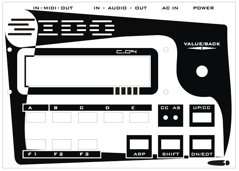
Thank you:) This almost white enclosure looks more like some medic device. Now im not sure which is better white or black. Brushed aluminium - like panel... in fact its self adhesive label laser engraved and thats why its not completely flat. Regards
-
Alpha Encoders – are they cheap rubbish? (MB6582)
C_04 replied to punkdISCO's topic in MIDIbox SID
Not for that they were in Yamaha A3000 - i just said that they were there. And my Yamaha has at least 10 years old. Also my Akai has ALPS encoders which never been replaced. Anyway encoders are your choice - buy what you want. I use ALPS. Cheers -
Last time ive bought ALPS from SOS Electronic and they were almost 9 PLN but im not sure about VAT there. 9PLN its about 2£ but ive bougt 11pcs of them. Problem is you may spend there at least 40£ and you need to have EU tax number. But im pretty sure you can find similar encoders in Farnell maybe. Ive spent 7 months in Leeds/UK so i had 40 min walking to their trade counter - i was so lucky man.:) Cheers
-
Alpha Encoders – are they cheap rubbish? (MB6582)
C_04 replied to punkdISCO's topic in MIDIbox SID
Hi Guys - why you not use ALPS encoders? These Alpha are crap encoders. ALPS you may buy for about 1,5$/pc - is that so expensive? I use in my SIDO only ALPS encoders and im sure they are for years. I use the same type that YAMAHA did in their samplers A3000 for example. Cheers C_04 -
Hi I could do that but unfortunately im in Poland. Anyway - you could check these leds that they are reverse soldered. Also if you have hc165/hc595 in sockests you may swap them (i mean hc165 with hc165 not hc165 wth hc595). Regards C_04
-
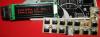
Hi This is almost done new prototype of final design SIDO. There necessary few changes only and everything may be produced:) Is no lcd there because im still waiting for some kind connectors. Cheers
-
Today ive got right DC/DC converter. Its small pcb from POLOLU and i will install them because i do not need to design new pcb. Of course i must change few things because now two pins on DC/DC must be shorted and finally DC/DC could be just soldered to main pcb in that way. Basicly its 5V, 550kHz step-down converter 300mA max and i dont need more. I may say thats not expensive thing. Sido at last has no noise:) Also today i gave one enclosure for laser cutting and panel label engraving, next thursday probably will be ready. Ive redesigned panels and graphics a little. Ciao P.S. Now SIDO needs only 163mA.
-
Hi Ive recorded some tracks. Here is "tron" - as you can hear there is background noise from MC34063 but nothing stop me to play even not finished SIDO:) These 10uF caps are way too small - i'll change them to 100uF otherwise no bass here. Cheers C_04 P.S. Second mixed track is one of some songs from September with a little mods. This is still noisy SIDO and i mixed it fast in Cool Edit Pro where i cant mix because its horrible there... also using headphones - for me its impossible to make not even good mix that way. So its just what SIDO can do. All tracks beside drum loops and some drum instruments were from SIDO. Even one drum loop is from SIDO. 3 tracks have been reverbed/delayed, 2 equed. Hihats loop, Bassdrum loop and Clap loop ive made manually - thats why may be not in time. Not in time is also this sticky sound like a CASIO - i have no idea why, probably something was wrong in midi track. This song is heavily compressed. Take a point its only for fun. tron.mp3 septemba fast mix.mp3
-
Hi Ive build that dc/dc converter and i must say 2 things: - switching frequency is too low and noise is really audible - after measuring now i see how linear 7805 is inefficient here. With 7805 whole circuit takes 0,35A and when DC/DC converter is sitting in place of 7805 - device need only 0,15A. After reading note for mc34063 i know that max switching frequency is 100kHz which is way too low because MC34063 produce a lot subharmonic frequencies. I remember now why it was working in my mic preamps. Anyway i did ordered ready to use DC/DC but 550kHz and maybe that will be solution. Still i can build 1MHz DC/DC converter. One thing could be problem here + i need to make a lot tests for EMI right now. I hope everything will be fine and there will be not necessary to use some shielding or etc to prevent radio frequency emitting. Regards C_04
-
Hi Ive checked that solution (sammichSID) its wrong for my purposes too. sammichSIDs enclosure is almost all open... looks like swiss cheese (whatever) there must be a lot of holes to do something with so much heat. As i pointed previously - i wanna use SERPAC enclosures which to my taste looks like something between YAMAHA CS1x, CS2x, CS6x, AN1x. Especially these angled sides are somehow like YAMAHAs. In fact only switching power supply is the solution i think and ive already designed - its not exactly switching... i mean it is but... using MC34063 + additional LC filter. Ive spent a lot of time with them. I did made many filters for microphone preamps to reduce noises from them. These were complicated designs actually STEP UP but above specifications. Regards C_04 P.S. In my design 7809 works even without any heat sink. If DC/DC converter will work in place of 7805 then i have what i wanted. And enclosure can be closed. No need for any holes for ventilation.
-
Hello After a lot of testing and measuring i must say that resistors are dead end. 10 ohms make only 10 C deg. 7805 cooler/colder. Beside that power dissipation produce also heat inside resistor so i have two sources of heating now... each about 53 C deg. Ive tried to connect 7809 and 7805 in series but no luck. Decision is to leave 7809 because it even not need heat sink and its now time to try DC/DC converter. I worked with them previously and it may be right choice for current times we live. Linear voltage regulators when has to dissipate a lot of voltage become really hot. In fact 5V rail is mainly digital part of circuit and should be no problems here. Second test was 7809 and in series 7805: Ive measured heat inside closed enclosure after some time. Im curious that in some circumstances become heating may damage entire circuit. I measured it in 25 C deg environment - after 30 min inside, sensor about 5 mm to heat sink and there were 43 C deg. Heat sinks were 57 and 64 (highest readings). Third test - lowering power supply: In this test everything is wrong. And of course is easy to explain. Each 78xx needs about 3V above we want to get. It means if for example i have 7805 then i need 8V to work properly. In first case when connected voltage was 9VAC - rectified was too low to work with 7809... then ive connected 12VAC and it was right choice but only in case when 7809 is there. Looks no chance to use 7812 for 6581. I dont know and probably any of you: what exact voltage it has when buying power supply. If for example we get 14VAC as ive got then we back on the starting point. I see few other possibilities: maybe bigger heat sink or 2 - one smaller inside another, drilling/cutting holes in enclosures which rises costs of manufacturing, trying another enclosure, making custom enclosure and of course using DC/DC converter. My first prototype has only one SID chip and heat there wasnt big deal. This is second and couple revisions been done (pcbs). Bye C_04
-
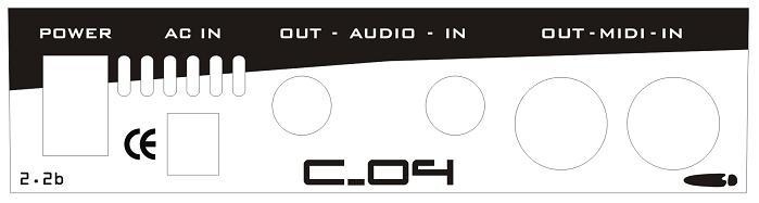
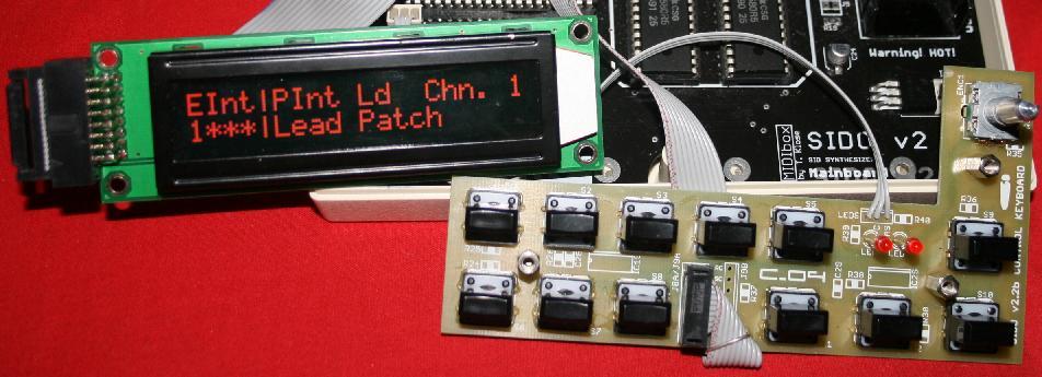
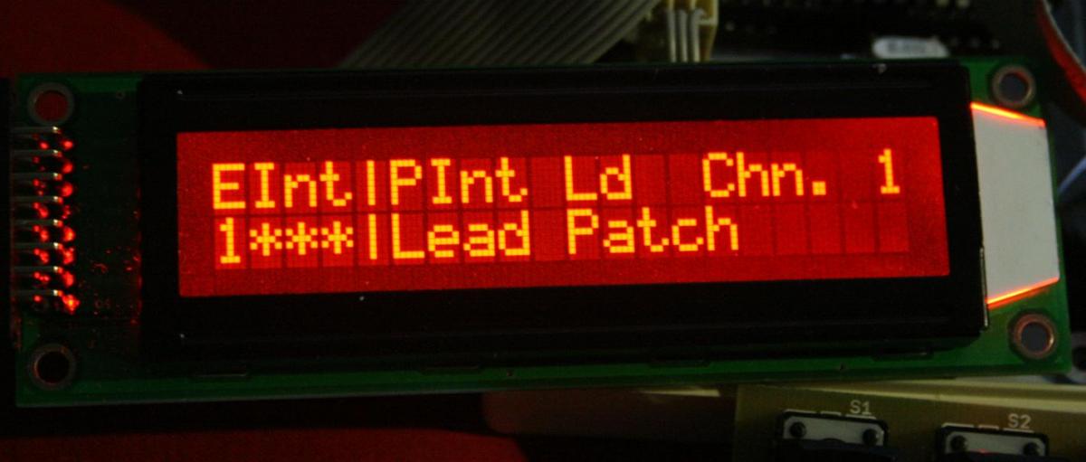
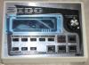
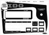
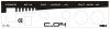
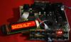
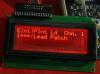
Hi After funeral in my close family and some other sad things im back here. Of course im still working on SIDO but im not describing it here because its mainly waiting for pcbs etc... so nothing interesting happen. I must say that i found few bad things in this entire design, unfortunately after second prototype and parts for another. These not so big things - just i dont like them:) For example schematic with backlight of lcd is wrong - transistor should be installed opposite, as it is now it doesnt work properly. I will fix that in next revision of PCB. Currently is #2 and im preparing 2.2b. These small boards are also been changed a little. Keyboard must be manufactured once again - eagle has changed GND to N$18 so one of switches is unconnected to ground. It everything may be fixed just with piece of wire but thats not for sale where it must work at first shot. Ive bought red negative LCD and problem is its not so bright. I also bought some previously used LCDs for about 4 EUR/PC and they work amazingly. These will be photographed soon. So... i would supply this beautiful design but if people want only brand new parts - there will be probably no way to use nothing that blue/white displays. They just average at my point of view - everything now has something blue which is boring in such quantity around. Finally ive added another led which is second and these are CC and Auto Save. This way shows batter that you may harm to your presets just by overwriting them. In this case when we have right led it will inform that Auto Save option is on. As i said before ive changed positions of ARP button and FILTER button. ARP is now close to SHIFT. Ive found that some of You may want to use 6581 chips or all these which require 12V and this design is not good for that - reason is that at 12VAC 7805 is going very hot. Probably when use here transformer with 9VAC everything could be much cooler. Anyway something must be done here and thats why ive added resistor in series it will be 6-8 ohm and 2-5W (6ohm could be 2W). All because these SIDs need almost 0,5A to work. Fortunately ive bought someday few pcs of these wall cords or however (these power supplies) 12VAC 1A each for 4Eur. And thats another reason to keep at 12V power working device. Another thing which is done is firmware - i mean setup to be correct. Sido keyboard use different connections that have other MBHP SIDs designs so another setup for firmware must be done. Heh in the meantime i made simple midi controller. It controls 8 tracks in CUBASE (can be modified to control more), has 8 potentiometers, 8 buttons and 10 leds. There also one hidden pin which shorten to gnd send STOP communicate (i do not use it because Cubase do not recognize it). Firmware is in asembler and is working on AT89S52. Last time ive bought 2 pcs of them just for little above 1 Eur with shipping. There also necessary ADC0808 or ADC0809 - ive had them at home. Some guy made PCBs for it because i hate to clean everything after etching;) Firmware is modified version of somebodys work but ive changed ports designations and CCs are sent. Maybe if somebody interrested i will publish it. I did this controller because i do not want to spend time for setting proportions for vocalist so he or she can do it by self. Firstly i wanted to use mixer with min 8 channels and send them all to vocal booth/cabin (however) but it then require to use 8 tracks from my sound interface which is half what i have in analog (2x MOTU 2408MK2 - i know its old but its excellent tool). Later i add some pics which in fact are nothing new - soldered pcbs and connected by wires. Ahh i forgot to say that i hate to solder countless these ribbon wires. Ive found that better and faster is to use here IDC connectors (these like FDD or HDD ATA/IDEE). Unfortunately when i solder connector as i want pins are not compatible they 1 to 2 and 2 to 1... 15 to 16 and 16 to 15. Should be of course 1 to 1, 2 to 2 etc. Im looking for another solution - small part of PCB just as converter/adapter for exact row connection. I did in fact this kind converter from IDC 16 to 1 row 16 (for displays). Thanks for such solution only what i need is solder goldpins and solder there just another small board 13 x 41 mm. Important is that i can solder entire device pretty fast without ugly cable connections. You know what i mean;) Regards Cheers Stay Tuned C_04 Sorry for this ground school English;) P.S. These yellow signs on 2x20 LCD in fact are not yellow. First picture shows how it looks - is more close to red led light. As you can see on 4th pic (4x20 LCD) there are installed small pcb which convert 16 pins in single line to dual rows 8 each. It could be installed by angle goldpins but i dont have them already at home. P.S. 2. Measured voltage is 14.2VAC in circuit and 16VDC - thats the reason why 7805 become so hot. Hehe these Chinese transformers with "12V" big info there. Not connected has 15VAC. Fortunately my device takes 0,35A and 10 ohm 5W resistor should help in any case. There should be at least 3V drop and of course i can set right resistor manually:).

-
Hi Thank you very much for yours really kind words. Anyway now i have to find few solutions for: switches, control board mounting to enclosure and few more. In fact i had this all designed but as you all know better is always better:) Sido can be easily changed from 8580 to 6581 - only you have to remove 7909 and solder there 7912 plus these small caps around SIDs which in option 8580 are 22nF - they have to be 470pF when 6581 (if i remember correctly). Also im not so good in digging into software - i would like to improve some things and i dont know where to start. There are so many files. For example old version of MBSID had possibility to connect directly leds which shows midi activity (in and out). I dont see this ability in newer designs. For me its important thing because sometimes im not sure SIDO is sending CC's. Also one of controllers has number 0 which is not recognizable for Cubase (sometimes I use my Sido as small midi controller). Of course there will be led indicating CC is on and Auto Write (or somehow) and these already works but better could be to see some movement here. Probably i will not apply this feature just because every version of firmware should be modified - now is almost the same sammichSID. Of course there different connections. My SIDO has EXEC or MENU button when you push encoder, sammichSID has separate button. But im thinking how i could improve that. Maybe shift should be there. Then i could use one hand to operate some functions but i can still operate one hand another functions hehehe. Thats the question - which of them could be more handy. All of you asking about kits - what about your SMT soldering ability? Two of colleagues here said that they can solder SMT. As i told SIDO may be partly assembled kit or full assembled. Only what you have is to put there your SIDs. Im thinking how many PCBs i should order. Maybe 3 as i told before will be best choice. Price will be probably not less than 30 EUR only for this mainboard. But these are very first PCBs. Cheers
-
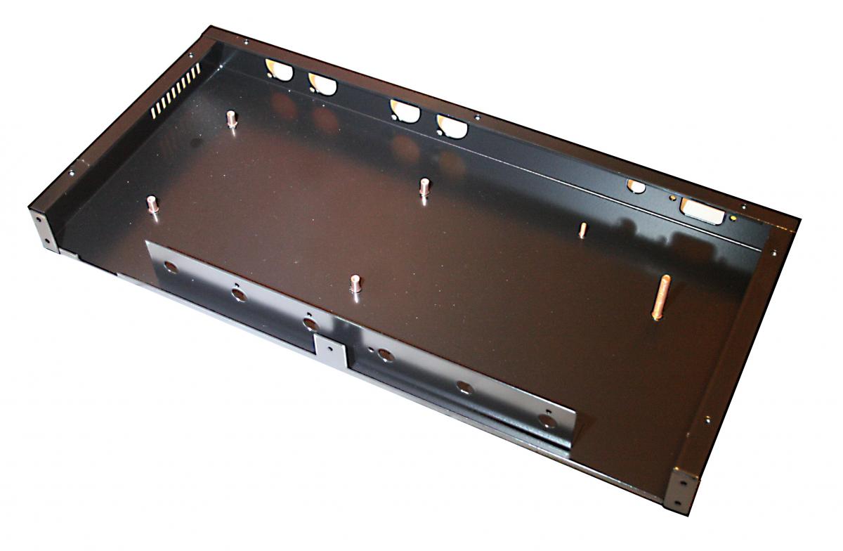
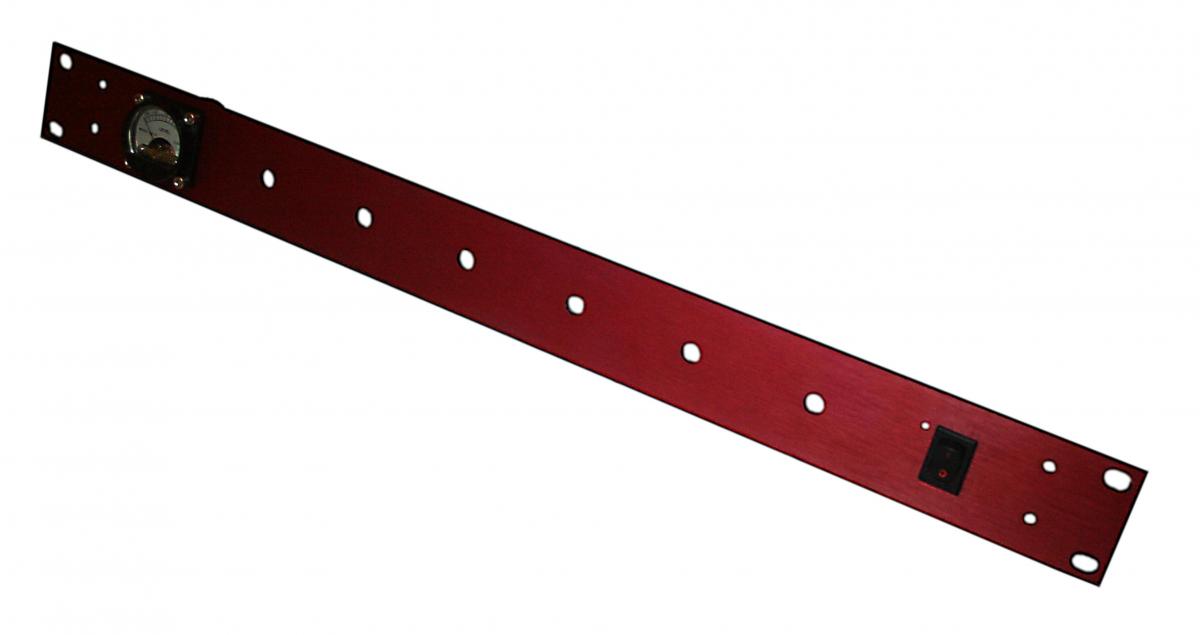
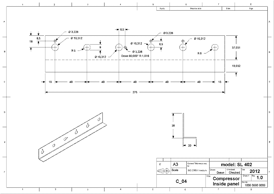
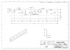
Hello Mr ilmentor and Mr nILS - this is somekind misunderstanding - you both still talking about obscure parts, obscure sources etc. And im assuring you that these optocouplers were purchased for testing only purposes and that really doesnt matter to fix here something beside that nothing is broken. These were 6n138 but also i have 6n137 (previous sido use this one) also many more not significant here optocouplers because for example CNY17 will be useless. I bought these 6n138 only 5 pcs and they cost me not much. If units will be in production but this depends from Thorsten all parts will be documented by invoices or vouchers. So you both really dont have to be scary about my help or post sale service. As i told to Thorsten i will provide warranty and i think this is much important than testing different parts from different sources especially they are for my private use and in prototyping phase. I said in - i think - first post here that im collecting good quality parts. Im telling once again: THESE 6n138 ARE NOT FOR COMMERCIAL USE. I have many ideas for different devices and i need these 6n138 - fortunately they were cheap and useful. Even so you dont asking about type of tin for soldering, etc but i know EU engineering rules (CE and a few EN, Rohs). I had few meetings about that in Leeds UK, also here in Poland/Katowice/Wroclaw/Poznan/Warszawa in certification units. Thats for future questions. Please understand me that isnt my idea to make mess for myself. Regards P. S. Attachments shows that im professional. These enclosures are one of my previous works. I designed them all (enclosures, panels). They were laser cut. Front panels are brushed aluminum. Sido could be also made that way but only if will be produced. Ive scaled down one of my documents for machining - its only for view here. I did not corrected dimensions because of machines tolerances.


-
Even Farnell may be obscure if you buying first time there;) So... Beside that almost every parts are from China or any part of Asia. I bought many times and many things from China and never had any problems. I could say that these problematic parts are made in EU but also Asia. Im not pretty sure. I remember devices which had polished ICs (devices were made in EU) and maybe that was starting point for idea to second life for these broken/cheap. Looks you dont have to warn me:) But you are right - unknown parts sources can be even harmful hehe. Ive seen burning chips and that was open fire not just psssst;) Cheers