
C_04
-
Posts
68 -
Joined
-
Last visited
-
Days Won
4
Content Type
Profiles
Forums
Blogs
Gallery
Everything posted by C_04
-
Meanwhile i made some cool pcbs ;) Nano SwinSids i could sell if at least 5 persons interrested then price could be 10EUR each + shipping. Maybe you dont know but Swinsid has 15 waveforms (mainly noises) while sid only 7. Another pics are MCV876 midi to cv converter - can work as synthesizer or CC. DAX is basicly MBFM but in my reincarnation - brother of SIDO. Cheers Greg
-
Hello It was little long time but finally i did it :) This upper keyboard is old one from SIDO v2. Current is 2.2bcv. Lower keyboard thats of course DAX control panel. As you can see DAX works on two pcs 7805 in different sizes... anyway before them ive installed DC/DC converter - thats for possibility to use any power supply (with higher voltage than 8V, may be 9V DC or AC - doesnt matter). Cheers Greg (C_04)
- 1 reply
-
- 2
-

-
Hi Then im asking Rowan now: What you can say about this backlight? Its shorted somewhere on LCD or maybe something wrong with sammichSID circuit? Did you tryied supply backlight directly using 5V? Did you measured it? Im really interrested:) Ill explain it why im so interrested - once ive had similar issue and reason was that wires soldered to lcd started to separate because i often bend them and one of them make a short. Maybe it wasnt exactly one of separated wires but definitely it was something like a hair. My lcd was then dull, blinking, restarting uC etc etc etc. I would like to know that LCD is damaged and need to be replaced or its repairable. OLEDs are not so cheap but if someone is rich then... hehehe Anyway LCD backlight may be powered directly from 12V via resistor maybe 1,2k - i would use that in first way. If too dark then 1k. sammichSID has some resistor to change backlight current, unfortunatelly i cant say which one because i dont have any pics with layout right now. Cheers G
-
Hi Did you repaired it?
-
Hi I know that some programmer software has possibility to change PIC IDs manually. I have no idea right now which of them you may use but in the past ive seen one who has that possibility. Another thing is if you not sure that it is programming well - use other software which tell you current PIC ID after change. If it will be still the same - you know the answer. Anyway try to find software where you can change IDs manually. Cheers
-
[solved] Sammich Bank Sticks problem [bad PSU & solder work]
C_04 replied to Shiftone's topic in MIDIbox SID
As i said previously - disconnect entire CS. Use only LCD and check whats happening. If no problems with stucking into ENV page then definitely you have something wrong with CS. Another thing is to check CS connector there may be weak connection. Next shorts!! Check every switch. Im not sayin that any of them is broken but it helps you localise which is which. ENV page if i remember - second is responsible or somehow. Next you may disassemble ICs from CS and mount only shift registers responsible for buttons, try different order. Blinking leds are last thing what you need now;) Cheers -
[solved] Sammich Bank Sticks problem [bad PSU & solder work]
C_04 replied to Shiftone's topic in MIDIbox SID
I could do flash the PIC for you but unfortunately im in Poland. Then we could try to say whats wrong more. Anyway in case your CS is shorted or any other problems may be there my advice is to disconnect entire CS. Keep only LCD connected. Use stronger power supply than this 0,5A and then try upload MIOS to your PIC if you wanna try it by yourself. Cheers ntire -
[solved] Sammich Bank Sticks problem [bad PSU & solder work]
C_04 replied to Shiftone's topic in MIDIbox SID
Hi I think there the power supply may be not efficient. 0,5A is a border/edge, you should maybe try 1A. I have 2 SIDO's which are very similar to sammich's and one with 2 SID's work perfectly on 0,5A 12V power supply but another with only 1 SID just starts to boot and restarts. Even lcd baclight is doing the same. It may be everything: memory's needs some current, capacitors has their ESR, PIC needs some current, leds needs current. You dont know how many need each element and you cant calculate it precissely. Even that you need something to loss on diode rectifiers and 7805 + 7809 regulators. This everething may produce your problems so try little stronger power supply. Another thing is that SID not properly started can be damaged. Prey to God because you have symptoms that both of your Sids are broken. They may be just symptoms but definitely you have to check them. Cheers -
Hi It may be interrested for any of you who wants badly to have MBSID. Its a sample pack of Commodore sounds and its free!!! Unfortunately i did not tested it yet but ive heard some demos and sounds promissing:) Here you have to scroll down and there close this rectangular banner - download link will be visible now: http://bedroomproducersblog.com/2012/11/06/bpb-presents-commodore-64-synthesizer-sessions-deluxe-free-sample-pack/ Here you can hear some demo: Cheers C_04
-
Hehehe Invention is a part what human calls intelligence. Cheers
-
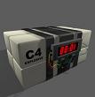
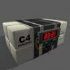
Ok after long break im back here. Some infos: ive installed in my SIDO 1MHz switching supply. It basicly reduce voltage from 12V or more to 7,5V which is then stabilised by 7805 and that helps so much. Another thing i observed: would be better to install here some OPAMP than these transistors and ill try this in newer version of SIDO, also some other mods like AMS1117 for uC and keyboard + LCD. But whats important... last days/months ive been and we still cooperate to solving some problems of MBSID and MBFM which were described here: Read posts written by Mr. Wylany. Finally he build his own MBSID which is based on designed by me - plans for SIDO. He (Mr. Wylany) designed metal box with wooden sides. As you can see its basicly SIDO in custom enclosure because ive made control keyboard, LCD been also connected and setup was programmed because its 18F451 uC. That rear board with audio connectors is also part from SIDO. Another things like MB CORE + SID Board were ready and working (delivered to me via post). He called this synth "GIANA". And here is: You may say: its not finished here and there but i think it will be... time is needed here:) Cheers C_04 P.S. Ive started also another job here: Reason in simple: Mr. Wylany had 2 synths without keyboards and LCDs - completely without CS and now its my case;)
-
Hi Meantime while im working on SIDO also ive made some parts for his younger brother DAX. DAX is basicly MBFM something like sammichFM. Ive called him DAX because of DX series of Yamahas synthesizers and... JADZIA DAX from Star Trek. As many of you know DAX was a symbiant living inside special selected persons and its somehow connected - you cannot expect whats inside. Beside of that Jadzia was pretty cute and nice lady. Another thing is that this small box can do things like big and heavy synths like DX7. Unfortunatelly ive stoped for sometime jobs on SIDO because some trouble with money (i think its many of us the same problem). But soon i will start again. I found few solutions. For example when ive put headphones into SIDO out hole... after relatively short time 7805 become hot. I didnt observed that when connected to some line in hole in another device. Seems that there would be very reasonable to put between some opamp and remove these transistors which are there. Also i think will be better to separate each SID for his and only his 7805. It will reduce heat. Anyway you can find in MBSID forum pictures of SIDO and imagine how similar SIDO and DAX will be. In fact its long work because im tryind to build line mixer for multieffects and because no funds progress will be slow.;) These boards are in SMT, upper board is double-sided and that lower single-sided. To me they looks very nice. Cheers C_04
-
kristal= i must say that partly you are right. There is possibility to use even 9V regulated power supply but you have to make a little mess inside sammich. Actually you have to use few jumpers. In normal operation when someone dont know what he is doing it may be dangerous. So i thought that we use bridge rectifier and 9V/12V stabilizer. In that case its true you cannot use 12V power supply when you have 6581 inside. Thorsten also wrote that on ucapps.de. Pvmpirxn you may buy something like this: http://www.ebay.com.au/itm/AU-Plug-AC-110-240V-12V-2A-switching-Charger-Supply-AC-DC-Power-Adapter-5-5-2-1-/131110981185?pt=AU_Gadgets&hash=item1e86d2ce41 Cheers and whats bad thats not me:)
-
kristal= im not saying that they dont know - im saying that someone made mistake. Maybe he thought about 12VAC and then everything is fine. Thinking and writing - these sometimes completely different things.;) Cheers
-
kristal= someone made mistake here: If using 6581, make sure you are using a regulated 12V power supply. Inside sammich we have bridge rectifier and there will be power loss about 1,5V. So how could be still working and have 12V after that rectifier when we plugged 12V regulated = DC? Cheers
-
Hi You use the same voltage like in Europe 230V but your sockets are like these in Australia. Which power supply you need depends what you have inside - i mean SIDs. If there 8580 then power supply may be 12VDC or 9-12VAC. If you have 6581 then you will need 15VDC or 12VAC. You may buy these small switching supply labeled 1A. Could be lower than 1A but unfortunately they sometimes wont start. Cheers P.S. The plug from sammichSIDe is 5,5/2,1 but ask also someone to be 100% sure.
-
I think you should check all ICs that you assembled them correctly. Check that maybe you have bad soldering points - its possible because you removed and installed ICs and that was enough to stop working entire device. Check that all legs are sitting properly in sockets, try squeeze once again each ic into socket. In Pic socket find gnd pins and measure voltage to 5V pins - all inside the same socket. Check oscillator is soldered well. After powering on your sammich are you able to see a belt in upper row (cursors row). When CS instaled check whats on lower pins signed gnd, 5V (RS and any digital is impossible to measure using simply voltmeter). After you open MIOS Studio do you see any initiations from sammich? It should be still something there even if optocoupler is not working. Dont swap cables - sammich is sending that via MIDI OUT. P.S. To me first steps here would be to check contrast pot and set it to see belt of cursors on LCD when sammich is starting. Second - to be sure system is working. And hehe i must say that it would be easier to repair it by myself than do it via online;) Price of these 2 PICs could cover all shipping costs but now you already have them. ;)
-
First at all. Do you have any backlight? Measure these 2 pins where you soldered wires. Im not sure where there is connected transistor but probably to B-. So there should be ground potential when transistor is short and you can remove this transistor and solder there maybe 300R resistor. Second pin you have connected wire to B+ should be 5V and measure that. All measurements make to ground: B- to gnd = short; B+ to gnd = 5V. Or something like that. Thats what you have to be sure to get LCD baclight. Any reasons are: pins swapped, broken LCD led, your connected wires are shorted to gnd. Measure and if there no 5V then try to find where is the closest point you can find it. Maybe as Shuriken said: you fried T1 (im not familiar with proper row order they numbered). You can even remove entire CS and put legs from any LED inside these pins you soldered some wires (lower than 1, 2 and 15, 16). Maybe add here 300R resistor in series with your led. Now you should know that you have backlight voltage and there is enough current to light it up. You may also try the same with yours LCDs. In optrex connect 5V to pins 1 and 2, to this older 15 and 16. Cell phone chargers often use lower than 5V and it will ok for your test - thats in case you not have any power supply. Otherwise you may use sammichSID power supply but add in series with your LCD led something about 1k. I dont know you have there any resistor already soldered. Please check your blue wire is that shorted to the ground. Looks your problems started before mod. So we have to try something different. Try maybe that sammich is responding for midi - i mean that you can play any sounds. Cheers
-
If you can please show us also CS for this sammichSID. I wanna be sure that you not doubled B+ pin. Dont change 595 if nothing bad happening. Cheers
-
Only PIC and LCD should tell you they working. So remove all other ICs. Once i had problems with fried 595 shift registers - they were big short for entire circuit. Another reason could be crappy sockets and its possible because you said that PIC is responding for MIOS other thing - bent legs. Cheers P.S. I would also suspect bad connections via connectors MAIN PCB vs CS PCB. Bad soldering points are also possible. No blinking/disco leds may be just because differences in software or wrong software/incomplete.
-
Hi Always what i do in such cases - back to this point when something been working. Replace LCD with this old one to check that in this configuration everything is still working. Reason could be contrast pot. Cheers C_04
-
Hi Is this device working? Where i may get schematics and firmware (if necessary). Cheers C_04
-
Hi I would make it so much simpler. Maybe its so simple for you but its not "must have" setup for you. As you know - you may find tons of free vst plugins on internet. I even have somewhere that quasi hammond plugin its made by someone from Germany (doesnt matter). Anyway you will need also vst host which is also free (i dont remember website). It depends which version you use - you may play only one plugin or you may use additional effects on it inside the same vst host. The same thing you can do using Cubase or any other sequencer supporting vst standard. You have to be sure that these plugins sends and receive midi CC - todays probably all do that. Another thing is to have midi chart for that specific plugin you wanna use. It will help a lot if not LEARN function there available. I would also separate keyboards and control surface. In this case you can use some old keyboard or other synthesizer with own keybord at the moment staying silent. That control surface could be a box with few drawbar pots and few buttons. To connect it together you will need that midi merger or something like that which is lying somewhere around in ucapps.de website. That control device could be made using some old uC like 8051. I even have working similar device but i use it as 8 channel level control in CUBASE + 8 buttons + 8 leds. Unfortunately it doesnt receive any CC but thats not important here because anytime i switch it on then all buttons are in ON position + leds are lit ON too; all potentiometers are sending last value. So you dont need to be afraid that you do not remember setups. Other hand its little pain when you wanna use previously saved presets in your vst plugin then pots dont shows appropriate value anymore - you have to move each one. This circuit also use ADC08 (8 in) which may be impossible to find or not easy;) To use 2 keyboards just add another. Its possible to use them by one midi cable - to Midi In of keyboard 1 from MIdi Out of keyboard 2 then Midi Out keyboard 2 to Midi In of your midi interface. Also somewhere you have to add this control unit as i described previously. In this type of connection you will not need miei merger - i think. I dont know your location but it can be cheapest way to get midi keyboard - you may buy old for example: Yamaha PSR-640 etc. Ive bought one of old Yamahas for 5 british pounds and probably FATAR keyboard inside because once Yamaha said that FATAR is producing them for Yamaha. So if you move - you may leave it for someone next:) Cheers C_04
-
Hi If you hear any sound (clear sound) then power supply is ok. I think you can check that there maybe invisible shorts - these thin like hair. Anyway also check other side - i mean uC and contacts here. If nothing help then simplest way to be sure is to check your LCD in another device or use another LCD in your setup. Maybe you have some friend or someone who can "rent" you LCD just for while. As i wrote in similar problem - topic, you may even buy lcd. These 1602 on ebay from China cost now 2$ incl shipping - i think youre rich enough;) If not sell then few bottles;) Not nice is only time to wait. Cheers C_04 P.S. Try maybe to solder both sides of LCD if metalization through holes could weak.
-
Ok ive seen them. I still cant say whats that third pcb. I think its really possible that will be opl3 synthesis - FM from YAMAHA. So in this case you have two synths in one pack;) Could you read mios version? There is 1,... and what? Now we have 1,9h but 1,9g also works fine. Your uC is 18F452 and now we use mainly 18F4685. Upload new mios here will be no problem, im not sure about setup. As i expected these cables were connected for future control surface, lcd has only soldered connector. So i could prepare for you LCD for example 2002 + IDC connector. You will need solder nothing. Bigger problem here is control surface. Ive no idea about your setup. Probably its one of these available to upload - nothing custom. Second even more problematic is this FM synth. There will be necessary to build everything the same way. You may contact me PM and use polish language if you able. Cheers