

BEBDigitalAudio
-
Posts
124 -
Joined
-
Last visited
-
Days Won
5
Content Type
Profiles
Forums
Blogs
Gallery
Everything posted by BEBDigitalAudio
-
Hi, for those interested by the technical details of the ASX board, I have manually redrawn the schematics. I have uploaded them here, in order to help any forum member who wants to recycle the ASX. The schematics are only intended to understand how the ASX can be used with other DSP firmware than the one available from iCON and Use-Audio. Note that the schematics are not complete (missing power supply and a few lines between the DSP and the codec), and I can not guarantee they are exact. The ASX, the iCON and the Plugiator are based on the same DSP board (the only difference is that Plugiator contains an extra CPU to handle MIDI, knobs and display) As you can see on the schematics, you have a direct MIDI IN on J1 (used for connection with CME UF keyboard) and J4 (used for connection with CME VX keyboard). These are "true" MIDI link, not TTL level. They can be driven directly by a MIDI OUT of a MBHP. During my investigations, I discovered some details about the MIDI protocol and the SPI protocol between the DSP and the ATMega32. These are just notes, but I can share them with any member who wants to implement a ASX synth controller based on MBHP. Benoit ASX schematics.zip
-
The problem wth the UseAudio / iCon plugins is that they are signed. You have to provide the serial number of the board when you connect to the website, and you can upload the DSP binary file only to the board with the same serial number. They protect themselves against piracy with that (and that's normal!), but this becomes a serious problem when your board dies and you want to replace it. I got the problem two times in the past: one of the first ASX board I bought stoppped working one day. It was replaced by the vendor (Thomann), but I was unable to reload the option plugins because the board had a different serial number, so my codes were not working anymore. The second time was simply because the manager software provided by Use Audio is simply awful, especially on the Mac platform, and I was suddenly unable to reload a ASX which was crashing because of a corrupted file (for those who read French, take a look to Audiofanzine website, I explain there what happened and how to recover the board) Benoit
-
Which announcement ?
-
Hi Justin, thank you for the information. I see that there are 4 pieces, available but they say "more are coming" (mehr ist unterwegs) If they are able to get more, then Amazon would become an interesting source for the project. The only problem with the X-Synth is that it is delivered only with 4 DSP programs (Minimax, B4000, Vocoder and an ARP emulation - can't remember which one). The other "plugins" are supposed to be available on Use Audio website, but not sure they can fit in the X-Synth (even if the X-Synth is *exactly* the same as the ASX. They are both made by inDSP) To be honnest, I know a way to unlock them, but this requires to "tweak a little" the PCB (the ATMega32 must be inhibited and you must load the binary file directly in the DSP from the MBHP). The problem is that any single error "kills" the board (the microcontroller becomes unresponsive). If any of you is interested by this tweak, just ask...
-
Waking up the thread after a long time with a little poll... :hyper: Who would be interested by having a modified version of the MB CV V2 in order to fit in a Eurorack? I am currently trying to figure a way to make one based on the STM32 board, mounted on the back of a PCB holding the connectors, with those connectors: - MIDI IN - MIDI THRU - USB MIDI - 2x16 LCD with 4 buttons for menu browsing - 6 or 8 CV/Gate outputs (maybe using the CV outputs with mode selection to turn selected channels into 0V/+5V signals) This would fit in 16 or 20HP module Benoit
-
It's pretty hard to tell, especially when the compiler is dealing with NEON. By the way, I do not think NEON was involved in the DFT test described before. The difficulty is that the gap between "general use" CPU and DSP is becoming smaller and smaller. Most CISC CPU now have dedicated DSP instructions (NEON or anything else), and many DSP integrate a general CPU (take a look to XMOS for example : they now provide a XCore chip with a ARM coprocessor! Same thing for Analog Device, with the BlackFin DSP. What is sure is that DSP cores are still beating all general use CPU in terms of pure DSP processing power, since they have an highly optimized architecture, most of the time with parallel FPALU, address generators, etc.. For example, a SHARC can execute up to 6 instructions in one cycle when the SIMD engine is activated, giving 2400MIPS peak power for 400MHz clock. The biggest challenge for now with the DSPs is the cost of the development chain...
-
I got bad news from them last week : they do not want to disclose their protocol... Technically, it would be possible to reverse the protocol, but it's probably a huge task. And I am afraid that they run a complete application in the DSP by default, which is only parameterized from the PC (so not possible to upload a new firmware in the DSP) However, I am still convinced that we can do something... and I will probably finish by making my own PCB for the DSP :rofl: And still about DSP, I also have something in my mind that I will submit to MB group very soon... Too early to reveal it for now, but I am sure that it will get interest from the community (with RTP-MIDI fully involved of course :shifty: ) And if any MB member goes to Frankfurt Musik Messe, do not hesitate to come on KissBox booth, I will be very happy to meet you there (we are on booth B93 in the Pro Light and Sound building)
-
Hello all, I have maybe found a "lowcost" solution for this project: the miniDSP board, made by a company based in Honk Kong (but owned by french people :happy: ). It costs only 185 USD, but the standard software restricts the use to their own DSP module loaded over USB. I have started to discuss with them about the possibility to access to specification of their protocol. The good thing is that they download the DSP code using SYSEX over a good old MIDI USB connection, so the STM32 MB would support it without any problems. And I also get some interest for some people based in France who proposed to get involved in the development of some modules of this project. Slowly but surely, we may get somewhere :sweat: Benoit
-
Hello everybody, sorry for this very long interrupt, but I have been extremely busy with some projects which are finally online My best wishes to all for this New year Thorsten have made some extremely important changes to the bootloader related to RTP-MIDI support, and I have upgraded the MBHP user's manual with related informations, plus many other details coming from the MBHP users. I stronly recommend you to download the new manual and read carefully the changes. Benoit
-
Hello all, I wanted to inform the MB fourm members using the RTP-MIDI OEM that a small issue has been found with the RTP-MIDI driver in 10.8, 10.9 and partly 10.10. This issue is not critical at all but it can give you a lot of stress to try to find the root cause :hyper: The symptom is simple : under some circumstances, the MIDI communication starts only after 10 to 30 seconds after the session has been opened. The Apple driver indicates that everything is fine, but you see the first MIDI data some time after the session is opened (the MIDI data are not delayed, the MIDI communication really starts after this period, so no MIDI data being received or exchanged meanwhile) Here is a decription of the problem: The RTP-MIDI OEM board can be a session initiator and a session listener. In other terms, it can be invited by the Mac and it can also invite the Mac. When the Mac is the session initiator (meaning that you use the "MIDI Network Control Panel"), everything is fine: when you click on Connect button, you are able to exchange MIDI data with the KissBox OEM in the next second. When the OEM module becomes session intiator (meaning you have entered the Mac address in the KissBox Editor as a destination for the session), you will see that the Mac is being invited and accepts the invitation just after the OEM module is powered, but you are unable to exchange any MIDI data for a period around 10 seconds (I have even seen some exceptionnal cases where it was taking 30 seconds). The Apple Control Panel also becomes quite unresponsive during this time, giving you the feeling that the driver is crashed. We have found the origin of the problem and we have a solution for it :sweat: The root cause is a different behaviour in the clock synchronization period when the Mac is session initiator or when it is invited. When the Mac is initiator, it starts a synchronization sequence immediately after the session is opened, and the KissBox OEM is able to synchronize with this first message. When the Mac is invited, it gets the same synchronization sequence, but from the OEM module this time. For a strange reason, the Apple driver waits until it gets something like 15 or 20 messages from the OEM until it starts accepting MIDI data. During this period, on 10.8 and 10.9 machines, the Control Panel seems stuck (in fact, it works again as soon as there are enough CK messages received) Do not ask me why the Apple driver acts like this... This problem does not happen with the Windows rtpMIDI driver. I have modified the synchronization sequence of the OEM, to make sure it sends enough CK messages in a short time to "unlock" the driver. This change is implemented in V2.2 of the OEM firmware. I will release it on the KissBox website probably today or tomorrow Benoit
-
Hello Borfo, yes, the RTP-MIDI boards are available. The price depends if you buy the OEM module alone or as a complete kit with the MBHP. If you want only the RTP-MIDI board, please contact my colleague Sierk directly at KissBox (via the contact page of www.kissbox.nl). We proceed like this to keep the price of the OEM board as low as possible when it's alone If you want the complete kit (the motherboard PCB + the OEM module), the price is 115 euros for the complete package (not including the postage fees). You can find the whole documentation on my own website : beb.digitalaudio.free.fr Benoit
-
The new OEM firmware is now available on the download page of KissBox website (V2.1) It solves a bug which occured when the module was receiving some SYSEX messages. Contact me if you need any help to install the new firmware Benoit
-
Important messages to all MB members who are using the RTP-MIDI OEM : I found a stupid bug in the firmware 2.0, which impacts the SYSEX messages (a message is being duplicated erroneously) I am working on the bug right now, I will try to deliver a corrected firmware as soon as possible (when I will have finished the tests of course). Sorry for this problem. Benoit
-
LCD does not start on STM32F4 board
BEBDigitalAudio replied to BEBDigitalAudio's topic in MIOS programming (C)
BTW, can an admin change the title of this topic to (solved) ? Thanks Benoit -
LCD does not start on STM32F4 board
BEBDigitalAudio replied to BEBDigitalAudio's topic in MIOS programming (C)
Root cause of the problem found and problem solved... Using my logic analyzer, I have been able to see that initialization sequence of CLCD_DOG was correct, but data stream for CLCD was corrupted. Looking in app_lcd.c source code, I saw that CLCD uses open-drain, but CLCD_DOG uses push-pull... I remembered that I changed the resistors going to J15A and J15B to 10k... and this cause all the troubles :shocked: probably because the signal does not go back to 1 fast enough when the open drain switches off. I just replaced R5/R6/R7/R8 by 1k (value given on TK's schematics) and now the LCD works like a charm. I will update the schematics of the RTP-MIDI MBHP to reflect this requirement. For TK : I tested bootloader V1.16, no more problem to store the display configuration data. The store command works every time now Thanks to all (and especially Thorsten) for your help on this problem Benoit -
LCD does not start on STM32F4 board
BEBDigitalAudio replied to BEBDigitalAudio's topic in MIOS programming (C)
Just verified once again with testlcdpin : D6 (and all other lines) are controlled as expected (verified directly at display connector, not on MBHP of course) Checked with the scope : D6 is toggling all the time as expected when I run a program talking continuously to the display Thorsten, following your idea of a problem with D6 (which would prevent the DDRAM address to go to 0x40 and then sticking to the first line), I made a simple program writing the following characters : <=>?@ABCD. The first four have D6 set to 0, the last four have D6 set to 1. They are displayed as expected, so I am quite sure that D6 line reaches the display correctly (the characters would be garbled otherwise) I will continue my investigations with the logic analyzer today, to see if I can find anything else. Benoit -
LCD does not start on STM32F4 board
BEBDigitalAudio replied to BEBDigitalAudio's topic in MIOS programming (C)
Yes, I understood that this was only solving the potential Flash initialization problem I will check today the whole cabling both with the scope and the logic analyzer, to see what could be wrong. -
LCD does not start on STM32F4 board
BEBDigitalAudio replied to BEBDigitalAudio's topic in MIOS programming (C)
Thanks Thorsten, I will try this new version tomorrow. I have checked all pins with a voltmeter using testlcdpin command, and the voltage was going correctly between 0 and 5V. By the way, I got the same result with 3 different LCD models. I will do another check, maybe the flat cable is cut somewhere and gives bad contacts. I will do a test with my logic analyzer too, I will post the traces if you want Benoit -
LCD does not start on STM32F4 board
BEBDigitalAudio replied to BEBDigitalAudio's topic in MIOS programming (C)
Better with pics... -
Miscellaneous images
-
-
From the album: Miscellaneous
-
LCD does not start on STM32F4 board
BEBDigitalAudio replied to BEBDigitalAudio's topic in MIOS programming (C)
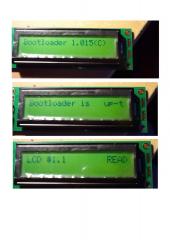
Hi Thorsten, thanks for these explanation, it's more clear for me now. However, I still have the strange problem with the bootloader, even with the 2x20 display. Here is what I did : - flash the bootloader in STM32F4DISCOVERY (to be sure it's completely initialized) and cycle power to restart completely - the LCD now shows the "default" state (one line of black squares on top) - when I type help in MIOS Studio, it says that current lcd_type is 0x00, current lcd_num_x is 2, current lcd_num_y is 1, lcd_width is 16 and lcd_height is 2. This is normal (default values when bootloader is flashed) Now, I type the following commands to activate my 2x20 display attached to J15A - set lcd_num_x 1 - set lcd_width 20 - set lcd_height 2 - store First store command is rejected : bootloader says "Failed to store new settings" Second store command is accepted. I see "New settings stored", "Initialize LCD#1" Since I see only one LCD being initialized (LCD is ignored) I assume the bootloader understood the parameters, telling there is only one display But the LCD is not displaying the READY message... Typing help now shows this: - lcd_type 0x00 - lcd_num_x 1 - lcd_num_y 1 - lcd_width 20 - lcd_height 2 which are the correct parameters for my 2x20 LCD (maybe I am wrong ?) Now, if I type set lcd_type 1, the LCD shows "LCD #1.1 READ" (so the display is now initialized properly, but second line does not appear correctly) Setting back to lcd_type 0 works too (but ignored if type was not 1 before) But the display does not initialize properly until I force it to type 1 or 0 even if it is displayed as a type 0 Here are some pictures of my 2x20 display after this init sequence, with the broken "return" (beginning of line 2 is displayed at 17th character of first line, which makes me think that there is a problem handling the 20 characters width) Benoit -
LCD does not start on STM32F4 board
BEBDigitalAudio replied to BEBDigitalAudio's topic in MIOS programming (C)
Hi Pete, thanks for your suggestion, I will try it tomorrow Benoit -
LCD does not start on STM32F4 board
BEBDigitalAudio replied to BEBDigitalAudio's topic in MIOS programming (C)
Problem partly solved... The display was not correctly activated in the bootloader. But three things look strange to me : - I have completely reloaded the bootloader using ST-LINK, and when I type help in the bootloader, I see that the current LCD type is 0 (CLCD). If I just define the other parameters, then store them, the display is not initialized. I had to set the lcd_type to 1, then back to 0, then store to see the display being initialized - I get a wrong display both in bootloader and application: the cursor does not move on the expected line. In bootloader, I see "Bootloader 1.015 ©" on the first line and "2014 T.Klose" on the second line, which is not correct (the "©" shall be on the second line). I made a test with two different displays (2x20 and 4x20) : same result. I also get the same problem with my application (text from the second line appears at the end of first line) - when I select 4 for lcd_height, it does not seem to work; my display still reacts as a 2x20 Any idea of the possible reasons for that ? -
Hello guys, I am facing a stupid problem with a LCD (4x20) connected to the RTP-MIDI core... It simply does not start. I am sure that I forgot something somewhere, but I can't find what I have verified all lines under the bootloader using the testlcdpin command, everything is fine I have set the display size to 4 x 20 in the bootloader In my app, in the APP_Background, I have put this sequence : MIOS32_LCD_Init(0); MIOS32_LCD_Clear(); while (1) { MIOS32_LCD_CursorSet (0,0); MIOS32_LCD_PrintFormattedString ("TEST"); } but my display clearly does not even initialize (I see the "default" squares when I set the contrast to the max). Moreover, I was expecting activity on pins PA8, PD3 and PD6... but nothing at all (checked with my oscilloscope), like if the LCD driver did not start at all. What did I miss ?