

Phatline
-
Posts
1,279 -
Joined
-
Last visited
-
Days Won
71
Content Type
Profiles
Forums
Blogs
Gallery
Posts posted by Phatline
-
-
hmmm has to do with UART
because when i add follwing line to mios_config.h
#define MIOS32_DONT_USE_UARTthe board is working normal,
i dont know what UART in this sense does? (USB-midibports??? Din-Midiports?) i dont know
this is all i can do, the rest has to be done who knows this application
-
this is writing while building (for those who looking into this tread, and having a glue...)
Quoteautark@Projekt:~/midibox/mios32/apps/controllers/midibox_ng_v1$ make clean
rm -rf project_build
autark@Projekt:~/midibox/mios32/apps/controllers/midibox_ng_v1$ make
rm -f project.hex
Creating object file for app.c
Creating object file for mbng_sysex.c
Creating object file for mbng_patch.c
Creating object file for mbng_event.c
Creating object file for mbng_din.c
Creating object file for mbng_dout.c
Creating object file for mbng_dio.c
Creating object file for mbng_rgbled.c
Creating object file for mbng_enc.c
Creating object file for mbng_ain.c
Creating object file for mbng_ainser.c
Creating object file for mbng_kb.c
Creating object file for mbng_matrix.c
Creating object file for mbng_cv.c
Creating object file for mbng_mf.c
Creating object file for mbng_lcd.c
Creating object file for mbng_seq.c
Creating object file for mbng_file.c
Creating object file for mbng_file_c.c
Creating object file for mbng_file_l.c
Creating object file for mbng_file_s.c
Creating object file for mbng_file_r.c
src/mbng_file_r.c: In function 'setTokenizedValue':
src/mbng_file_r.c:1902:8: warning: unused variable 'is_range' [-Wunused-variable]
Creating object file for mbng_file_k.c
Creating object file for terminal.c
src/terminal.c: In function 'TERMINAL_ParseLine':
src/terminal.c:494:11: warning: implicit declaration of function 'MBNG_FILE_K_Write' [-Wimplicit-function-declaration]
Creating object file for scs_config.c
Creating object file for main.c
Creating object file for strtol.c
Creating object file for tasks.c
Creating object file for list.c
Creating object file for queue.c
Creating object file for timers.c
Creating object file for port.c
/home/autark/midibox/mios32/FreeRTOS/Source/portable/GCC/ARM_CM3/port.c: In function 'prvPortStartFirstTask':
/home/autark/midibox/mios32/FreeRTOS/Source/portable/GCC/ARM_CM3/port.c:282:1: warning: stack usage computation not supported for this target [enabled by default]
Creating object file for heap_4.c
Creating object file for startup_LPC17xx.c
Creating object file for mios32_srio.c
Creating object file for mios32_din.c
Creating object file for mios32_dout.c
Creating object file for mios32_enc.c
Creating object file for mios32_lcd.c
Creating object file for mios32_midi.c
Creating object file for mios32_osc.c
Creating object file for mios32_com.c
Creating object file for mios32_uart_midi.c
Creating object file for mios32_spi_midi.c
Creating object file for mios32_iic_midi.c
Creating object file for mios32_iic_bs.c
Creating object file for mios32_mf.c
Creating object file for mios32_sdcard.c
Creating object file for mios32_enc28j60.c
Creating object file for mios32_timestamp.c
Creating object file for mios32_bsl.c
Creating object file for mios32_sys.c
Creating object file for mios32_irq.c
Creating object file for mios32_spi.c
Creating object file for mios32_i2s.c
Creating object file for mios32_board.c
Creating object file for mios32_timer.c
Creating object file for mios32_stopwatch.c
Creating object file for mios32_delay.c
Creating object file for mios32_ain.c
Creating object file for mios32_usb.c
Creating object file for mios32_usb_midi.c
Creating object file for mios32_usb_com.c
Creating object file for mios32_uart.c
Creating object file for mios32_iic.c
Creating object file for printf-stdarg.c
Creating object file for core_cm3.c
/home/autark/midibox/mios32/drivers/LPC17xx/CMSIS/src/core_cm3.c: In function '__get_PSP':
/home/autark/midibox/mios32/drivers/LPC17xx/CMSIS/src/core_cm3.c:451:1: warning: stack usage computation not supported for this target [enabled by default]
Creating object file for usbhw_lpc.c
Creating object file for usbcontrol.c
/home/autark/midibox/mios32/drivers/LPC17xx/usbstack/src/usbcontrol.c: In function 'StallControlPipe':
/home/autark/midibox/mios32/drivers/LPC17xx/usbstack/src/usbcontrol.c:127:6: warning: variable 'pb' set but not used [-Wunused-but-set-variable]
Creating object file for usbstdreq.c
Creating object file for usbinit.c
Creating object file for app_lcd.c
Creating object file for glcd_font_normal.c
Creating object file for glcd_font_normal_inv.c
Creating object file for glcd_font_big.c
Creating object file for glcd_font_small.c
Creating object file for glcd_font_tiny.c
Creating object file for glcd_font_knob_icons.c
Creating object file for glcd_font_meter_icons_h.c
Creating object file for glcd_font_meter_icons_v.c
Creating object file for midi_router.c
Creating object file for midi_port.c
Creating object file for midimon.c
Creating object file for uip.c
Creating object file for uip_arp.c
Creating object file for uiplib.c
Creating object file for psock.c
/home/autark/midibox/mios32/modules/uip/uip/psock.c: In function 'psock_send':
/home/autark/midibox/mios32/modules/uip/uip/psock.c:179:3: warning: variable 'PT_YIELD_FLAG' set but not used [-Wunused-but-set-variable]
/home/autark/midibox/mios32/modules/uip/uip/psock.c: In function 'psock_generator_send':
/home/autark/midibox/mios32/modules/uip/uip/psock.c:218:3: warning: variable 'PT_YIELD_FLAG' set but not used [-Wunused-but-set-variable]
/home/autark/midibox/mios32/modules/uip/uip/psock.c: In function 'psock_readto':
/home/autark/midibox/mios32/modules/uip/uip/psock.c:274:3: warning: variable 'PT_YIELD_FLAG' set but not used [-Wunused-but-set-variable]
/home/autark/midibox/mios32/modules/uip/uip/psock.c: In function 'psock_readbuf':
/home/autark/midibox/mios32/modules/uip/uip/psock.c:301:3: warning: variable 'PT_YIELD_FLAG' set but not used [-Wunused-but-set-variable]
Creating object file for timer.c
Creating object file for uip-neighbor.c
Creating object file for memb.c
Creating object file for clock-arch.c
Creating object file for network-device.c
Creating object file for lpc17xx_emac.c
Creating object file for uip_task.c
Creating object file for dhcpc.c
Creating object file for osc_server.c
Creating object file for osc_client.c
Creating object file for uip_terminal.c
Creating object file for freertos_utils.c
Creating object file for keyboard.c
Creating object file for ainser.c
Creating object file for aout.c
Creating object file for max72xx.c
Creating object file for ws2812.c
/home/autark/midibox/mios32/modules/ws2812/ws2812.c:75:2: warning: #warning "WS2812 driver not supported for this derivative yet!" [-Wcpp]
/home/autark/midibox/mios32/modules/ws2812/ws2812.c:111:12: warning: 'ws2812_send_double_buffer' defined but not used [-Wunused-variable]
/home/autark/midibox/mios32/modules/ws2812/ws2812.c:119:12: warning: 'ws2812_state_ctr' defined but not used [-Wunused-variable]
/home/autark/midibox/mios32/modules/ws2812/ws2812.c:122:11: warning: 'ws2812_rgb_values' defined but not used [-Wunused-variable]
Creating object file for notestack.c
Creating object file for diskio.c
Creating object file for ccsbcs.c
Creating object file for ff.c
Creating object file for file.c
Creating object file for md5.c
Creating object file for seq_bpm.c
Creating object file for seq_midi_out.c
Creating object file for msd.c
Creating object file for msc_bot.c
/home/autark/midibox/mios32/modules/msd/LPC17xx/msc_bot.c: In function 'MSCBotBulkOut':
/home/autark/midibox/mios32/modules/msd/LPC17xx/msc_bot.c:268:13: warning: variable 'iChunk' set but not used [-Wunused-but-set-variable]
Creating object file for msc_scsi.c
/home/autark/midibox/mios32/modules/msd/LPC17xx/msc_scsi.c: In function 'SCSIHandleCmd':
/home/autark/midibox/mios32/modules/msd/LPC17xx/msc_scsi.c:155:14: warning: variable 'dwLBA' set but not used [-Wunused-but-set-variable]
Creating object file for blockdev_sd.c
Creating object file for scs.c
Creating object file for scs_lcd.c
Creating object file for mini_cpp.cpp
Creating object file for freertos_heap.cpp
-------------------------------------------------------------------------------
Application successfully built for:
Processor: LPC1769
Family: LPC17xx
Board: MBHP_CORE_LPC17
LCD: universal
-------------------------------------------------------------------------------
arm-none-eabi-size project_build/project.elf
text data bss dec hex filename
269514 152 64256 333922 51862 project_build/project.elf
10000000 B __ram_start
10007fd8 B __ram_end
2007c000 D __ram_start_ahb
20083bc0 B __ram_end_ahb -
i jumpered J27 in order to come into bootload-mode... (in order to upload new code...)
then downloadet the actual bootloader, and made sure that i used the correct LPC1769 since mine is a 1769
then dowloaded the actual github zip from https://github.com/midibox/mios32
set the environment variables to lpc... restardet
built the NG-code from the downloadet github.... ("make clean", then "make")
uploadet the build project.hex
removed the J27 jumper (then mios made a softreset
mios writes:
no response from CLCD.... (off course nothing connected)

Init DHCP

PHY initialized

SD Card not found
no problem up to this point
but after reconnecting the USB-Cable (aka hard-reset) it goes into HARDFAULT ---aka blinking rapid
so it is confirmed the actual NG-Firmware was not tested for a LPC-Core (maybe someone made changes, but tested it only on STM32?
-
cant say, may a other can help,
but from where to you have that NG Version, because on http://www.ucapps.de/mios32_download.html
i see only 1.036! (i searched, and wanted to look if this also happend to a virgin ng...)
-
ok, cant say what the display says (since it there is no) but the board led is blinking rapid. and mios studio does not recognize the board.
i tested it on the LPC-Core, plugged into my laptop
when i plug the usb-cable to a wall-5V adapter, its not blinking.
so yes - this is a software thing, not a hardware.
about mios-config... there is a lot activated.... do you use all the things in there? (#define MIOS32_SRIO_NUM_SR 32 and so on...)
-
LPC or STM?
-
go in mios32_config.h (a file in the root of your project)
and deactivate all you dont need with:
#define MIOS32_DONT_USE_SYS
#define MIOS32_DONT_USE_IRQ
#define MIOS32_DONT_USE_SPI
#define MIOS32_DONT_USE_SPI0
#define MIOS32_DONT_USE_SPI1
#define MIOS32_DONT_USE_SPI2
#define MIOS32_DONT_USE_SRIO
#define MIOS32_DONT_USE_DIN
#define MIOS32_DONT_USE_DOUT
#define MIOS32_DONT_USE_ENC
#define MIOS32_DONT_USE_AIN
#define MIOS32_DONT_USE_MF
#define MIOS32_DONT_USE_LCD
#define MIOS32_DONT_USE_MIDI
#define MIOS32_DONT_USE_OSC
#define MIOS32_DONT_USE_COM
#define MIOS32_DONT_USE_USB
#define MIOS32_DONT_USE_USB_MIDI
#define MIOS32_USE_USB_COM
#define MIOS32_DONT_USE_UART
#define MIOS32_DONT_USE_UART_MIDI
#define MIOS32_DONT_USE_IIC
#define MIOS32_DONT_USE_IIC_MIDI
#define MIOS32_USE_I2S
#define MIOS32_DONT_USE_BOARD
#define MIOS32_DONT_USE_TIMER
#define MIOS32_DONT_USE_STOPWATCH
#define MIOS32_DONT_USE_DELAY
#define MIOS32_DONT_USE_SDCARD
#define MIOS32_DONT_USE_ENC28J60then strip down all you dont need in your app.c.... if you have to include stuff from mios, copy it into your project directory, and include it with "display.h" instead of <display.h>, strip that file down (remove all stuff that is for other microcontrollers like the lpc, or other things you dont need) and maybe you got an glue, whats going on....
cant say more, but would really like see mios on a better faster bigger microcontroller then the stm32f407vgt6, since my project itself is already limited by the ram and flash capabillitys...hopefully someday somone comes that have the will and knowledge to port that... i dont have the knowledge (so forget me)
-
hmm, i would first jumper all J5A/B/C - if they are open... so you have no noise from the ADCs... I know USB has nothing to do with ADCs, but that i would do first ( because that happend often when it not booted up)
A virgin NG1.037? or somekind modified? (like the font thingi?)
post what you have in "mios32_config.h"
else i dont know, mostly i get hardfault when writing negtativ values intos unsigned integer variables (aka use s16 instead of u16 variables), or doing mess with custom freertos tasks.... i am really no expert for NG... you could post the code here (zip) and i can try if it does the same, have a stm or lpc here to test..
-
linux oder windows oder mac?
hab bisher nur in linux gearbeitet,
da geh ich immer auf: /etc/environment
und kopier dann immer für STM32:
PATH="/home/autark/midibox/gcc-arm-none-eabi/bin:/home/autark/program:/usr/local/sbin:/usr/local/bin:/usr/sbin:/usr/bin:/sbin:/bin:/usr/games:/usr/local/games:/snap/bin:/home/autark/app:/home/autark/midibox/gcc-arm-none-eabi/arm-none-eabi/bin"

MIOS32_PATH=/home/autark/midibox/mios32
MIOS32_BIN_PATH=/home/autark/midibox/mios32/bin
MIOS32_BOARD=MBHP_CORE_STM32F4
MIOS32_FAMILY=STM32F4xx
MIOS32_GCC_PREFIX=arm-none-eabi
MIOS32_PROCESSOR=STM32F407VG
MIOS32_LCD=universal
und für LPC
PATH="/home/autark/midibox/gcc-arm-none-eabi/bin:/home/autark/program:/usr/local/sbin:/usr/local/bin:/usr/sbin:/usr/bin:/sbin:/bin:/usr/games:/usr/local/games:/snap/bin:/home/autark/app:/home/autark/midibox/gcc-arm-none-eabi/arm-none-eabi/bin"

MIOS32_PATH=/home/autark/midibox/mios32
MIOS32_BIN_PATH=/home/autark/midibox/mios32/bin
MIOS32_BOARD=MBHP_CORE_LPC17
MIOS32_FAMILY=LPC17xx
MIOS32_GCC_PREFIX=arm-none-eabi
MIOS32_PROCESSOR=LPC1769
MIOS32_LCD=universal
rein (ich hab mir diese textblöcke abgelegt, und wo abgespeichert, das ich nur noch copy paste machen muss), ich vermute unter windows kannst dir einen script schreiben, der die entsprechende Variable EXPORTIERT, z.b. auch mit einen einfachen dos-fenster, wost den skript startest, und lpc oder stm reinschreibst, und dann wirds exportiert... aber wie genau? keine ahnung, und MAC 0 ahnung.
und starte dann neu, ab da an sind meine SYSTEM VARIABLEN (zu linux: environment variables) dauerhaft gespeichert... falls ich dann ein älteres projekt wieder bearbeite, stell ich auf LPC um, und starte neu...
...aber hast schon recht... das ist müßig... war ich bisher zufaul mir mein leben zu erleichtern ;)
-
@ cherry: the switch itself you can get already from eg https://www.reichelt.de/tastaturzubehoer-c8099.html?ACTION=2&GROUPID=8099&SEARCH=*&START=16&OFFSET=16&CCOUNTRY=445&LANGUAGE=de&r=1&SID=967792150a00d890464504461a66ae529d97182e528c945af4544
caps: amazon, alibaba,.maybe.some thing like that: https://www.amazon.com/dp/B00FYO8EDC/ref=mp_s_a_1_5?keywords=flat%2Bkeycaps&qid=1675511770&sr=8-5&th=1&psc=1
https://www.cherrymx.de/en/dev.html
the low profile is maybe interesting....
-
 1
1
-
-
@poti; if the shaft's center is in the end on the same position - so same frontpanel holes can be used.... and: when soldering the thing: first mount the pcbs with loose potis on the frontpanel then solder it (and document this in the "how too build"...
@ - : use thermal destress traces (cant remember the kicad word) when using groundplanes, so you can desolder the the poti much easier.
-
1
-
-
passt scho ; ) next quest

- michi.
-
you work with local files in the project folder? or do you put the files in the mios-path?
if you put your folders in the project folder you have to go a other route:
* my example file "tm_V4" >>> try to "make" it,
* and study what i have written with "" and <>
include "blabla.h" (is a local file - so you have to put the file in this project folder)
include <blabla.h> (is a file in the mios path) > so you have to put the file in the mios-path
it would be usefull if you zip your project, post it here - to see how you work, and what may the problem is.
-
make clean
make
?
and change in headerfile:
extern const u8 GLCD_FONT_JBIG[];
to
extern const u8 glcd_font_jbig[];in the makefile low and high letter dont cares, but i think in headers you have to write it exact like it is written in the font.c.... (but maybe i am wrong)
-
i have really cheap and old (but unused) green backlight 2x40 Screens at home, i dont need them (you pay the postage and they are yours)
i bought 10 off them decades ago, actuall i only use SSD1306 Displays - i will not need the 2x40 anymore.
where are you from (EU?)
-
control hardware yes, if it is well documentadet on the wiki (shematic, board screenshot)
I too work with kicad since decades... and very sucessfull now with my actual projects - i was wondering but i planed it in kicad, and most off the boards where working 100% out off the Box (pick and place JLCPCB), ok i had a design fault on one, but that was solved with a wire-done.
actual projects
http://wiki.midibox.org/doku.php?id=triggermatrix5
http://wiki.midibox.org/doku.php?id=daw-ableton
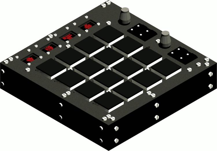
http://wiki.midibox.org/doku.php?id=openpad
software: cant help, write my own Mios-based code, havent look into MidiboxNG - since it is a script, for me more easy to write it directly in C, (need to understand all, else i understand/learn nothing...) - so no help from this side
had good expierences with jlcpcb... also with the Pick and Place service
FrontPanels: maybe cheap CNC-Laser-Cutting from pcbway?
https://www.pcbway.com/rapid-prototyping/CNC-machining/CNC-Laser-Cutting-Services.html
suggestions? Maybe use Eurorackformat, so it can be used outside of your box too?
suggestion, where usefull (wo sinnvoll) use J89 Serial Chain directly onboard (like encoder with ledring boards) to reduce wireing - a simple button board dont needs that of course....
*** if you go the Serial Chain way, then buffer the Serial chain on each module to keep the digital Signal Quality intact (very necessery)
*** buffer: search for SN74LVC1G17DBVR in this shematic: http://wiki.midibox.org/lib/exe/fetch.php?media=phatline:blm16x16-shematic.pdf
maybe use pick and place ready smd technologoy like i did:
that makes it smaller, and less to solder, less to debug, the plastic packages stays in china, more economical special when ordering more pcbs, by that of course a module should fit all the boxes (a exotic 1 man needs it module 10times fabricated is 9 too much...)
i think i dont have to say, that you should choose "Basic" Parts, and not "extendet parts" on JLCPCB, - off course on most modules you have at least one or two extendeet parts... but for example a DINX4 or DOUTX4 can be made with basic parts only... but when you also want to pick and place all the pin headers - these are extendet parts, how ever ... you may look on my last modules a bit
http://wiki.midibox.org/doku.php?id=tm5-dindoutgate
http://wiki.midibox.org/doku.php?id=doutx2dinx1
if you use long cables to your Displays + u use more displays then one - on the modules, use a display driver (no more walking lines)
http://wiki.midibox.org/doku.php?id=displaydriver-smd
what else? if you make ground or other PCB-Planes, then setup kicad that it make 1-2mm space arround solderpoints - else the Soldering Man could make shorts, or electrocemical oxidations or solder flux-low-residance could make there some problems (after years), special when the Solderstop-Pain is scratched a bit...
... and so on...
PS i hate this wooble feeling off this LeMec Buttons (the last board you posted) - these Buttons are not good (for my taste)
I love to work with this ones: https://www.reichelt.de/at/de/eingabetaster-schaltspannung-24v-fuer-led-sw-dtl-2-sw-p7248.html?&trstct=pos_0&nbc=1
they are expensive, but they last decades (in use, and also if you order 300 off them and let them lye arround, after 15 years they still work)
They have good CLICK, like a mechanical Keyboard.
your leMec Buttons are like a mixture off Rubberdome and "i have to touch this buttons into one direction X=0 Y=0 else it want switch"
or you could use:
https://www.midiphy.com/en/shop-details/140/4/5pcs-matias-quiet-click-tactile-switch-
they are cheap but big... (aka take away a lot of Frontpanel space)
or maybe you use cherry switches or simulars.... they are all 1000% better then this leMecs... ( you notice i hate them)
-
1
-
-
ok i got it...
if you have for example follwing Shiftregister Chain- Scenario:
DINx3 > DOUTx4 > BLM (instead of BLM > DIN > DOUT... which is not possible because of not having a J8/9 output on the BLM)
go to blm_scalar.c
and change following:
/////////////////////////////////////////////////////////////////////////////
//! Initializes the BLM_SCALAR driver
//! Should be called from Init() during startup
/////////////////////////////////////////////////////////////////////////////
s32 BLM_SCALAR_Init(u32 mode)	{

	  // define default configuration (can be changed during runtime)
	  int mod;
	  for(mod=0; mod<5; ++mod) {// count thru Scalar Modules

								// DOUT
								int mod_sr_offset = (3 * mod) + 4;	// 4: DOUTX4 OFFSET      3: 1-Cathode, 2-Color1, 3-Color2

								blm_scalar_config.dout_cathodes[mod] = mod_sr_offset + 1;

								int colour;
								for(colour=0; colour<2; ++colour)
								blm_scalar_config.dout[mod][colour] = mod_sr_offset + colour + 2; // offset 2..3(..4)


								// DIN
								blm_scalar_config.din[mod] = mod + 1 + 3;	// 3 = DINX3 OFFSET

								}
  .......................................
have fun!
-
On 4/14/2021 at 4:05 PM, Phatline said:
to add an DINx4 module in front of the BLM16x16+x-Module, do following...
blm_scalar.c
add the SR_off Part....
/////////////////////////////////////////////////////////////////////////////
//! This function gets the DIN values of the selected row.
//! call it from APP_SRIO_ServiceFinish() hook!
/////////////////////////////////////////////////////////////////////////////
s32 BLM_SCALAR_GetRow(void) {

		// decrememt debounce counter if > 0
		if( blm_scalar_button_debounce_ctr )	{ --blm_scalar_button_debounce_ctr; }

		// since the row line of the buttons is   identical to   the row line of the LEDs,
		// we can derive the button row offset from blm_scalar_selected_row                  909  >>>>>>>>>>>>>>>>   here is the offset?
		int selected_row = (blm_scalar_selected_row-1) & 0x7; // &: bitwise AND     0x7: 7

		// check DINs
		int mod;
		for(mod=0; mod<5; ++mod) {	// 5: Module-Nr
									int sr = blm_scalar_config.din[mod];

									static u8 SR_off = 4;		// Shiftregistor Offset -- if you have a DINx4 Module before the BLM-Module
									if( sr ) {	MIOS32_DIN_SRChangedGetAndClear(sr-1 + SR_off, 0xff); // ensure that change won't be propagated to normal DIN handler
												u8 sr_value = MIOS32_DIN_SRGet(sr-1 + SR_off);

												// ignore as long as debounce counter != 0
												if( !blm_scalar_button_debounce_ctr ) {

																// determine pin changes
																u8 changed = sr_value ^ blm_scalar_button_row_values[mod][selected_row];

																if( changed ) {
																				// add them to existing notifications
																				blm_scalar_button_row_changed[mod][selected_row] |= changed;

																				// store new value
																				blm_scalar_button_row_values[mod][selected_row] = sr_value;

																				// reload debounce counter if any pin has changed
																				blm_scalar_button_debounce_ctr = blm_scalar_config.debounce_delay;
																				}
																}
												}
									}

		return 0;
}
now i need this for the DOUT-Registers... i got the 16x16 working with following code .... but the Extra-XY stay dark - any Idea? cant get forward, since Latigid Ons BLM has no J89 thru, i have to put the BLM at the end of the SR-Chain (3xDIN, 4xDOUT in front off the BLM)
///////////////////////////////////////////////////////////////////////////// //! This function prepares the DOUT register to drive a row DOUT-SR-OFFSET HERE!!!!!!!!!!!!!!! //! should be called from APP_SRIO_ServicePrepare() ///////////////////////////////////////////////////////////////////////////// s32 BLM_SCALAR_PrepareCol(void) { // increment row, wrap at 8 if( ++blm_scalar_selected_row >= 8 ) { blm_scalar_selected_row = 0; } // select next DOUT/DIN row (selected cathode line = 0, all others 1) u8 dout_value = ~(1 << blm_scalar_selected_row); // apply inversion mask dout_value ^= blm_scalar_config.cathodes_inv_mask; // output on CATHODES* registers u8 SRo_off = 4; //Shiftregister offset int mod; for(mod=0; mod<5; ++mod) { int sr = blm_scalar_config.dout_cathodes[mod]; // 5: Module-Nr if( sr ) { MIOS32_DOUT_SRSet(sr-1 + SRo_off, dout_value); } // SR-CHain: BLM > Dout.... //if( sr ) { MIOS32_DOUT_SRSet(sr+3, dout_value); } // SR-Chain: DoutX4 > BLM } // output colours for(mod=0; mod<5; ++mod) { int colour; // 5: Module-Nr for(colour=0; colour<2; ++colour) { // 2: Color-Nr int sr = blm_scalar_config.dout[mod][colour]; // Module 8 Rows Color Blink u8 STEPs= blm_scalar_led[mod][blm_scalar_selected_row][colour][0]; int val; if (blinky && BLM_BLINK_ACT) { // turn of the blinking Steps u8 FLAM = blm_scalar_led[mod][blm_scalar_selected_row][colour][1]; // compare FLAM and STEPs with Bitwise XOR! val = FLAM ^ STEPs; } else { val = STEPs; } // Set it if( sr ) { MIOS32_DOUT_SRSet(sr-1 + SRo_off, val); } //Shiftregister offset, val); } // SR-CHain: BLM > Dout.... //if( sr ) { MIOS32_DOUT_SRSet(sr+3, val); } // SR-Chain: DoutX4 > BLM Geht zumindest für ie Hauptmatrix 8080 /// ///////////////////////////////////////////////////////////////////////////////////////////////////////////////////////////////////////////777 } } return 0; } -
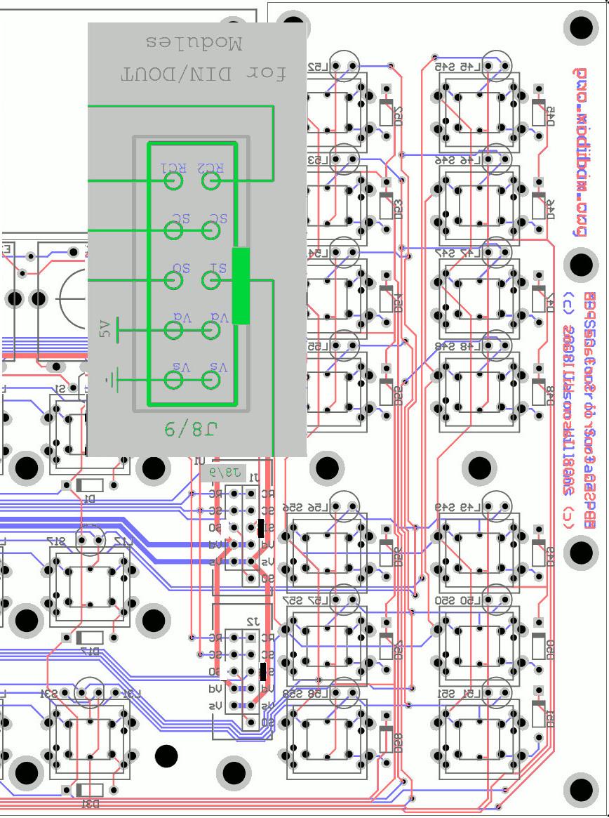
Aaarg, you are right, i forgot that its soldered on the backside...
looking from the backside off the PCB the Nose should look to the right side
see this mirrored Picture, with corrected Noses
-
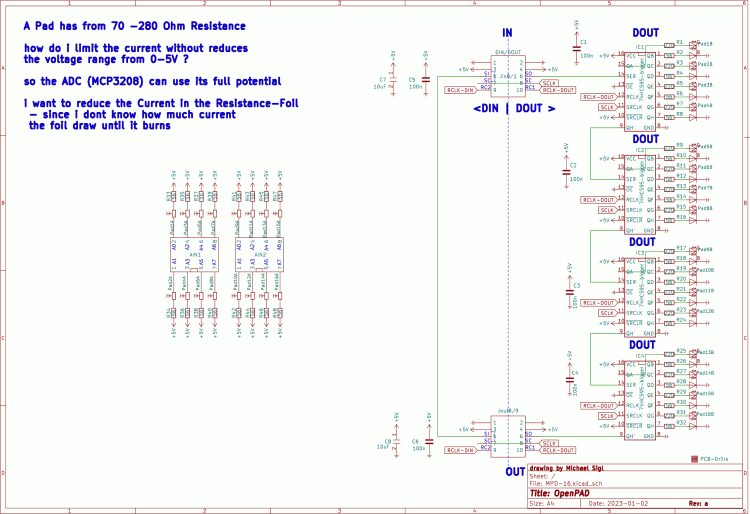
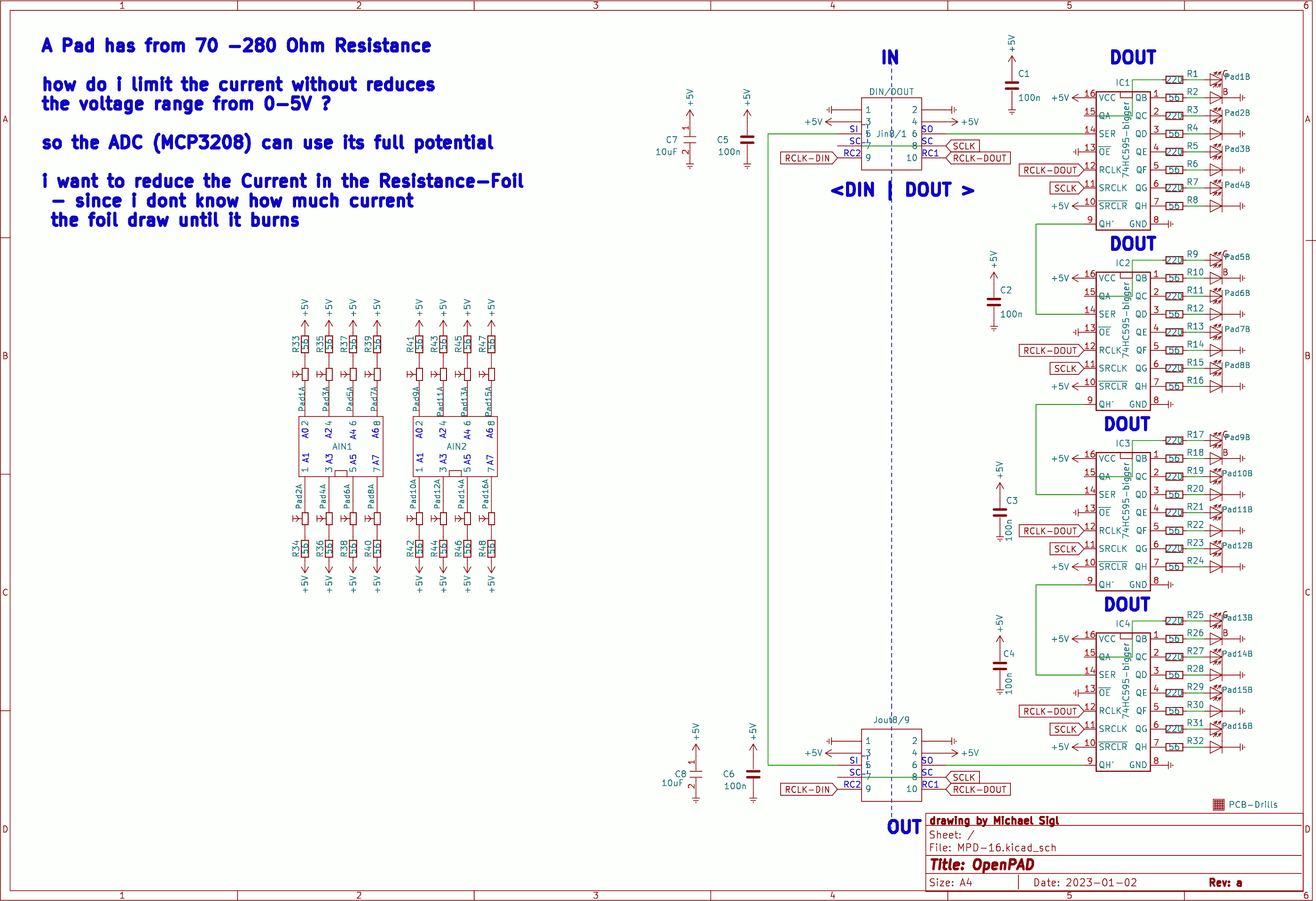
the quest still is:
the akai Resistive Foil - has a resistance from 280 Ohm if you measure diagonal between the corners.
Our MCP3208 wants 0-5V.
How do i limit the current going thru the Foil, without reducing the 0-5V Range?
OP-Amps? how? Thx 4 Input
-
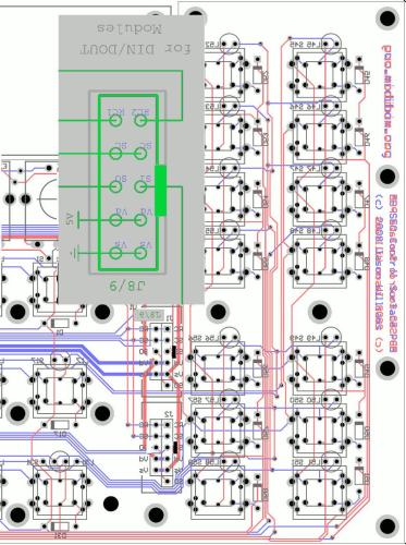
this should help (see the green) - I have drawn Rectangels for the Connectors/or Pfostenbuchseś NOSE
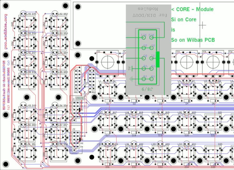
(EDIT: this Picture is only right if the Cable is soldered on the Top side - which nobody does --- see 2 posts below this one for the correct picture from the backside)
(PS the PCB is shown from TOP aka Component-Side)
AND its a 1:1 Cable,
Si is only otherwise Labeled > for example:the DOUT Pin "So" on the Core Module - is labeld "Si" on the Controllsourfacethe DIN Pin "Si" on the Core Module - is labeled "So" on the Controllsourfacethats the logic behind most all Modules - for example the SD-Card-PCB has the same OUT<<>>IN Mirroring - but thats all only Labeling, the wiring is 1:1.>>>wilba had done drawn his Board that Si is Si and So goes to SoSo you just have to know how to crimp a Wire 1:1, and you are good.
(PS2: your picture off the cable is so small i cant identify anything there...)
-
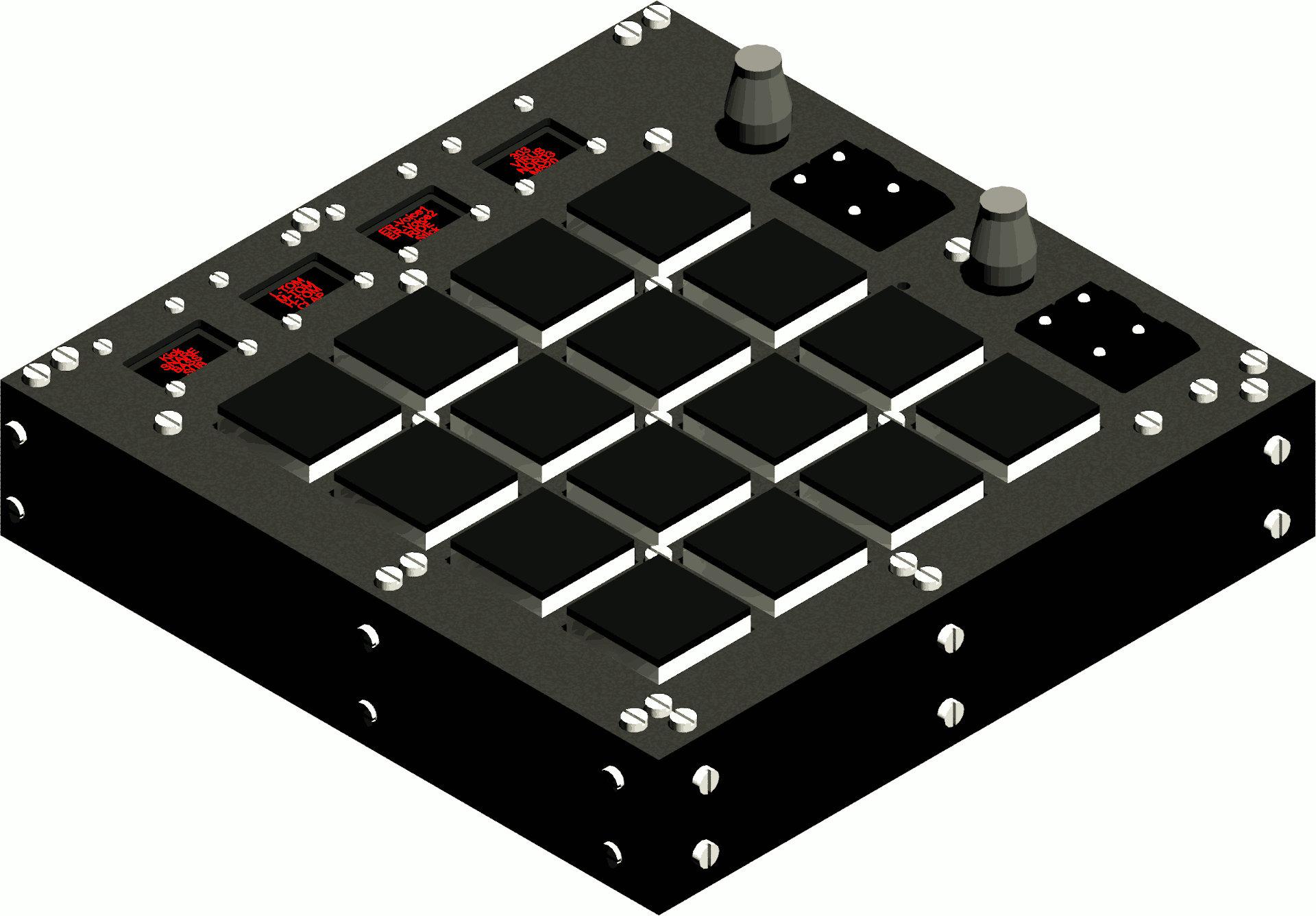
Hi, i recently buyed a Akai MPD226... i hoped i could use it standalone with MIDI-TRS/DIN Hardware... but LED Feedback doesnt work (aka Notes from a Hardware Sequencer give no Response to the PADS)
- short the Akai Firmware sucks.
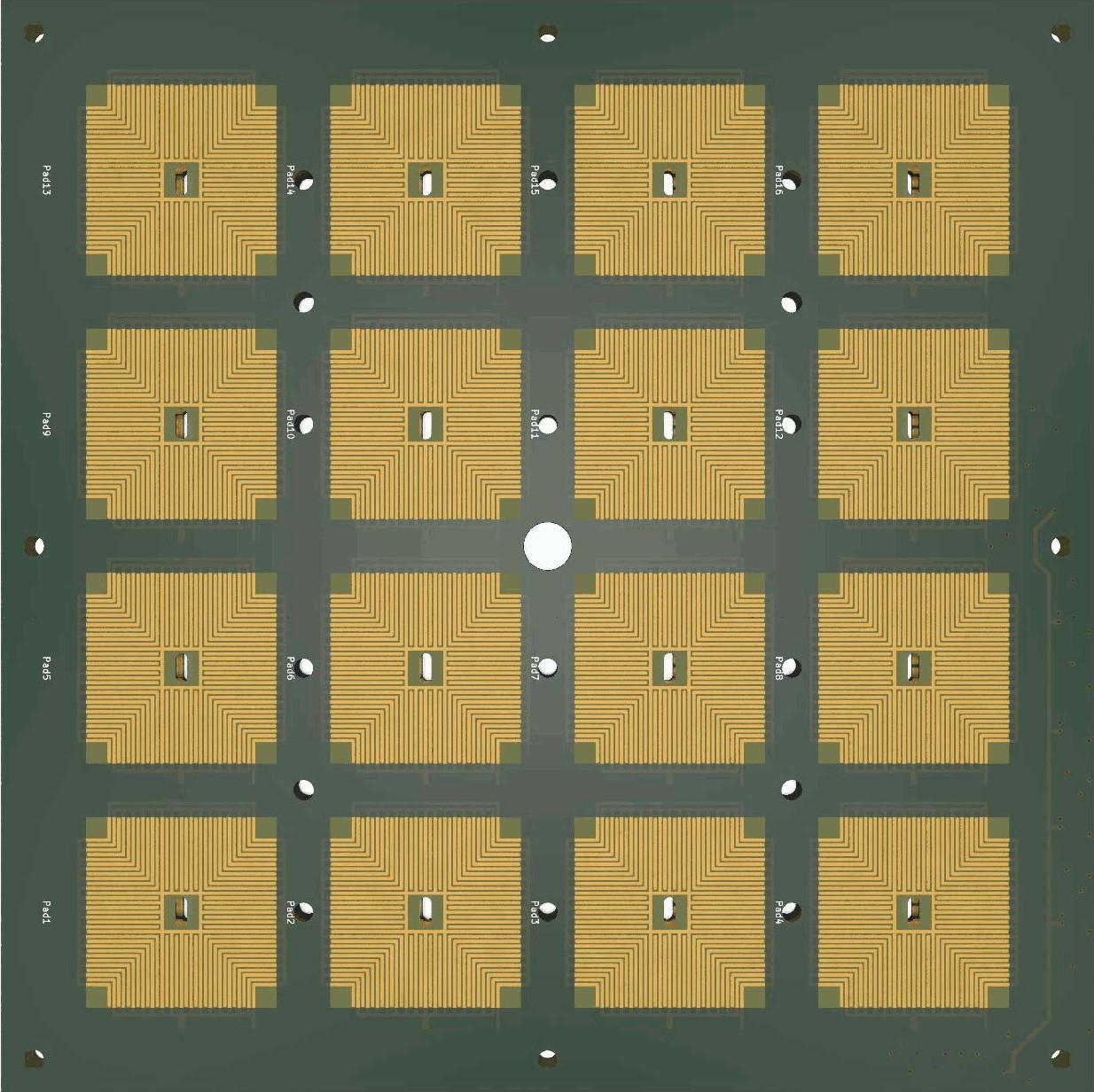
I made a teardown, searched on the MPC-Stuff website... and made PAD-Footprints for KICAD, made shematic and so on:
Result: OpenPAD
I dont use the same shematic as Akai did... the multiplexed 4 Inputs of a STM32F103 with some HC595. My goal is to use 2x MCP3208 and connect them without switching to the PADs.
SO I HAVE A QUESTION:
the akai Resistive Foil - has a resistance from 280 Ohm if you measure diagonal between the corners.
Our MCP3208 wants 0-5V.
How do i limit the current going thru the Foil, without reducing the 0-5V Range?
OP-Amps? how? Thx 4 Input
I too have drawn a Core PCB 4 Pick and Place... incl STM32F407VGT6 ;)
-
dont know anything about MBNG-Script, nor with Cubase (except that i tryd it - and had the feel "its not my workflow, and i cant customize my workspace here")
I had those Mackie MCUs and wrote a MaxMSP (standalone) Groovebox for it, that was 2012 - so the knowledge is anywhere in my brain.... http://wiki.midibox.org/doku.php?id=triggermatrix&s[]=triggermatrix
about MCU since it uses sysex, sounds do-able, what that means in MBNG-Script - you will have to find out, if you ever come to a point where you see that MBNG-Script cant do what you want (i dont know) , you can call me to discuss for a more custom code.
-
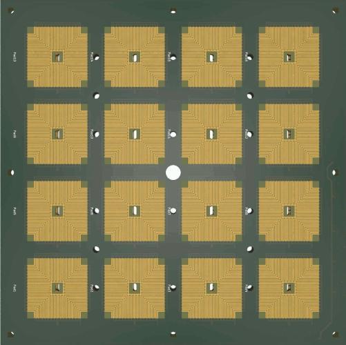
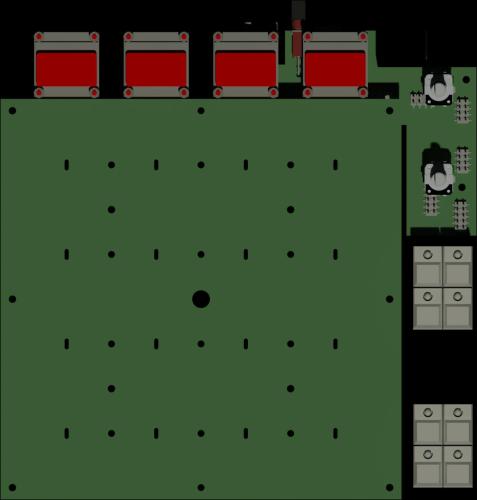
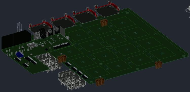
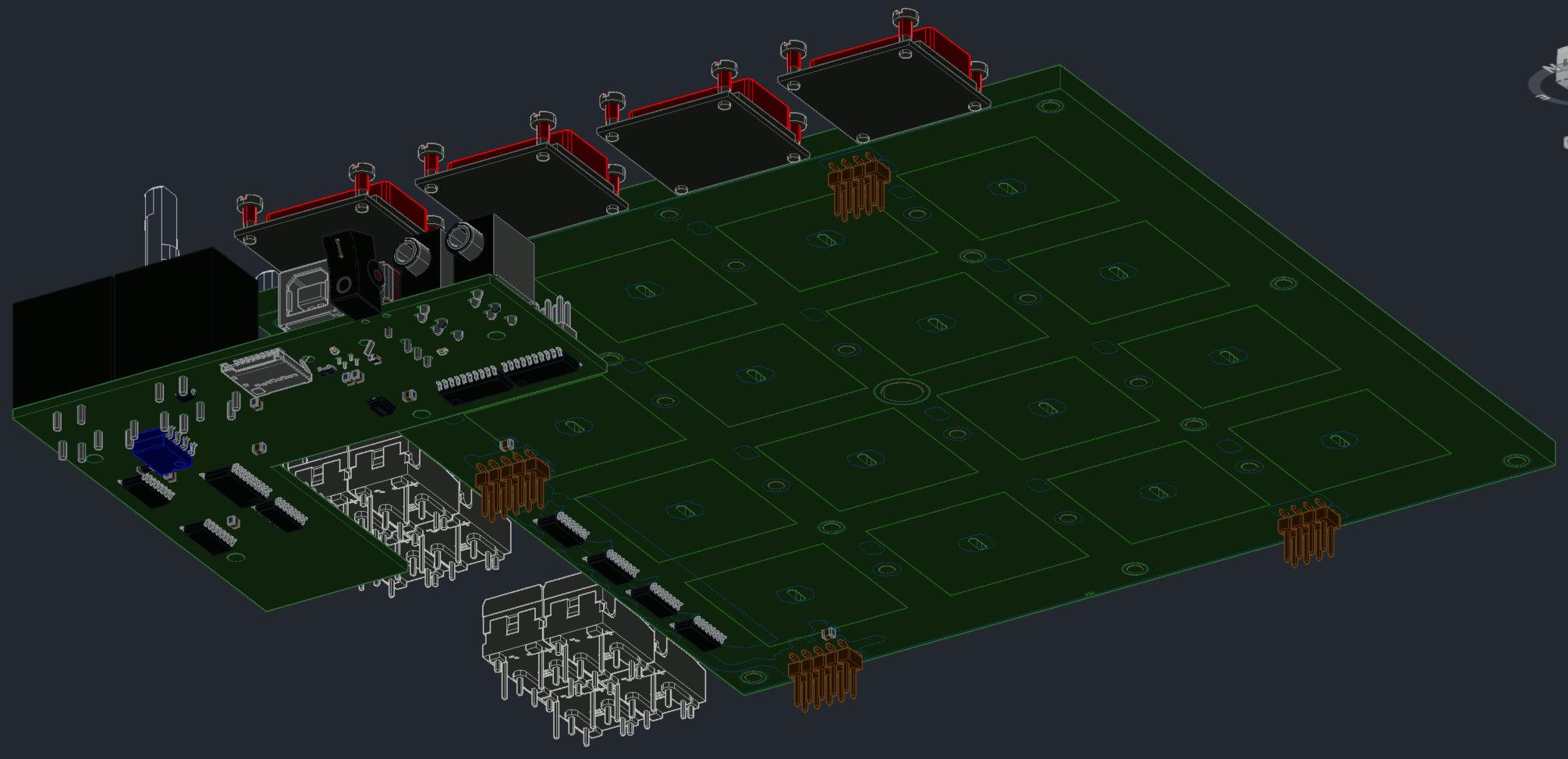
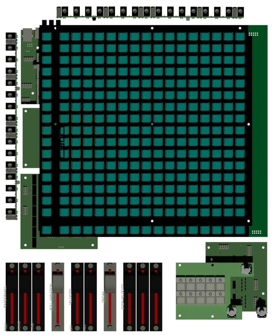
the next generation off Triggermatrix,
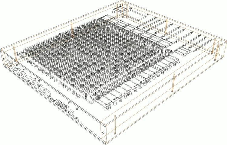

with insights to shematic, the board-files i will not set free... the Pictures from the Boards are for debugging reasons only.
where possible, i made pick and place ready boards - to reduce soldering time... at this point the big BLM16x16 board is not pick and place ready.
WIKI:
-
 1
1
-


Built a controller keyboard using NG (issue #1: low velocity resolution, issue #2: random pitch wheel values)
in MIDIbox NG
Posted · Edited by Phatline
look into ng documentation if there can be set a offset for the middle position so it stays on a position... because pots directly to the core is always a bit random... better use for example: http://www.ucapps.de/mbhp_ainser8.html
then you have less random values
also check the quality off PSU...off course a faulty pot can be the reason too