

Phatline
-
Posts
1,279 -
Joined
-
Last visited
-
Days Won
71
Content Type
Profiles
Forums
Blogs
Gallery
Posts posted by Phatline
-
-
@RIO linker? this is not a software swich/link... its a hardwareswitch, and if he had that switch in the firstcase, he might have solved the problem already.
Since he was talking about a new SD-Card, and of corrupted Files, i thought there is maybe no hardware-config file (or 0kb file) on the new card. --- later on he posted a picture of the SD-Cards filestructure... and yes i now see there is a 22kb File on it > so yes he dont need the Hardwarefile because there is one - congrats!
wilba: http://wiki.midibox.org/doku.php?id=wilba_mb_seq&s[]=wilba
-
Just now, phillwilson said:
im really sorry...im not sure what this means.... i assumed this was a link, but where is this /midibox_seq_v4_096/hwcfg/wilba/MBSEQ_HW.V4 ? on the card?on the site? sorry if im not understanding.
"
you may also need to put the hardware config file on the root of your new sd-card:
i guess its a wilba without track-position LED-Matrix?
then this is the hdwg-file:
/midibox_seq_v4_096/hwcfg/wilba/MBSEQ_HW.V4
(is in the zipped firmware)
"
i already wrote where it is (read! and take it serios), it seems that you dont have a Wilba-Interface, looks like a standard DIY-Interface?
i would first try to go into bootload mode via.:
http://wiki.midibox.org/doku.php?id=home:mbhp:module:bootloader-switch
build this switch, set the switch to bootload mode, reboot the core, then open mios studio, upload new SEQV4 code.
-
you may also need to put the hardware config file on the root of your new sd-card:
i guess its a wilba without track-position LED-Matrix?
then this is the hdwg-file:
/midibox_seq_v4_096/hwcfg/wilba/MBSEQ_HW.V4
(is in the zipped firmware)
-
ok i am in austria... so maybe a other one?
-
 1
1
-
-
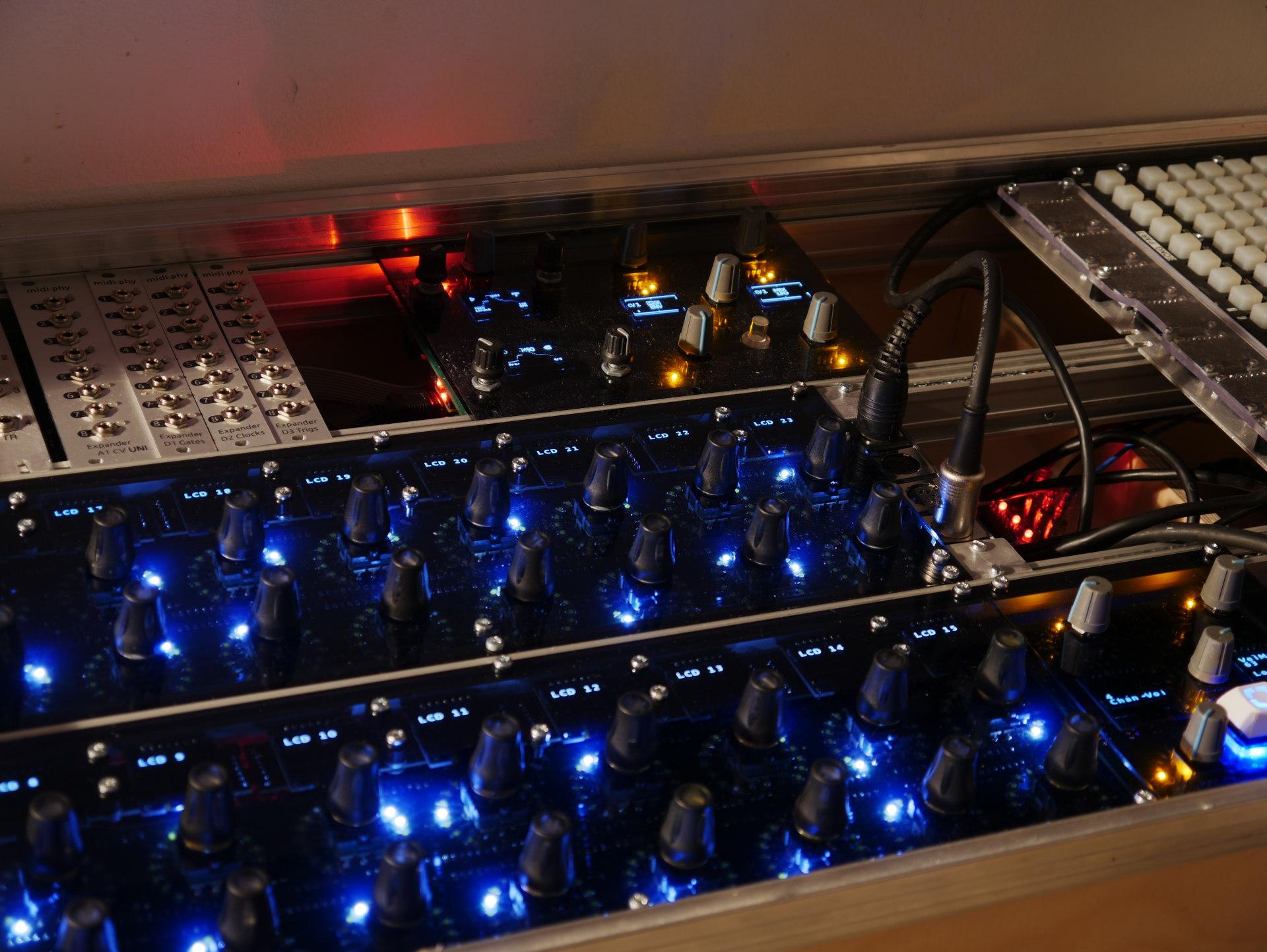
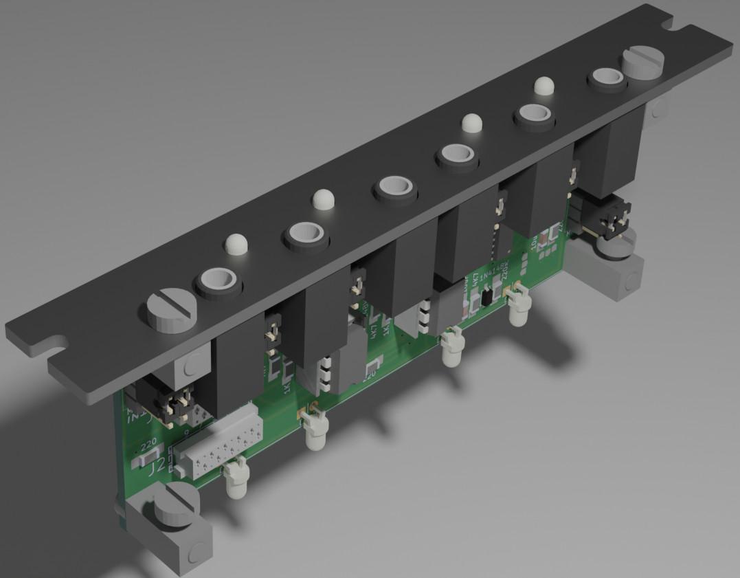
in a eurorack:
-
where you located?
-
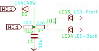
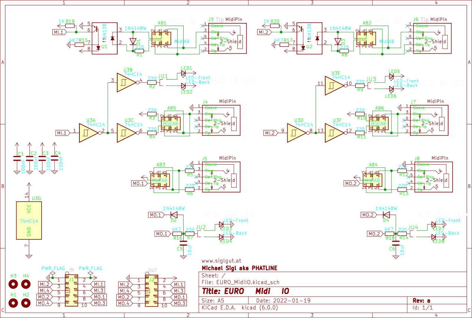
I tryd this Variant for Midi-OUT Activity LEDs... as it works with NoteON-OFF Messages, it comes to its limits when transfairing high datarate - like midiclock. The steady Charge and discharge of C5, messes up the Datasignal, so it cant be used.
Since i already used all Pins of 74HC14, i now need a second HC14, or some other Buffercircuit (for 2x Midi-OUT Activity LED) - any Ideas for that are welcome!
-
quick update... i debugged Rev.A with a view Wires
(and it works - almost),
by doing this i made Rev.B - and updatet the wiki.
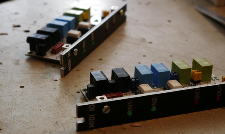
For Rev. B i have to Cross J1 to J2, since i made a 1:1 Connection between this 2 Headers... - and that is not true... true would be:
I2>I4, I4>I2, O2>O4... and so on
-
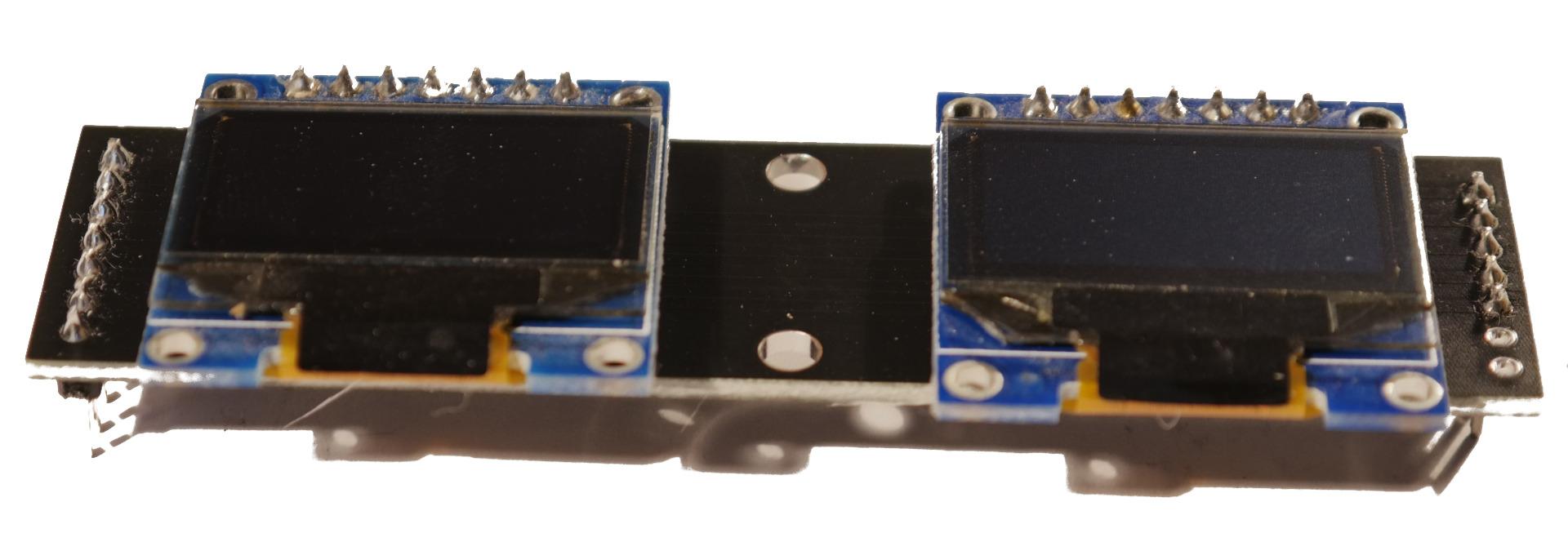
yes they worked...

and it looks very nice...

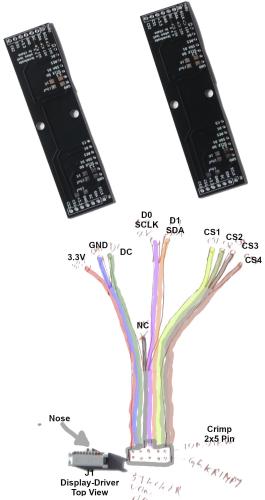
i highly recommend latigid onś Display driver: http://wiki.midibox.org/doku.php?id=display_driver
i tryed the multiplexing via J10B with a DoutX4 but i had walking lines here and there, so i took the display driver and it just works!
This is the pinout from the display driver J1-J8 to connect 4 screens aka 2 PCBs to it.
i made a video (build) - but i want to write some code first, so i have unit which i can work with it (to have a video jam for it...)
so you can order at least the PCBs - this take some time... in the meantime i change the frontpanel: i would remove the mounting holes for the LRE8x2 first...
-
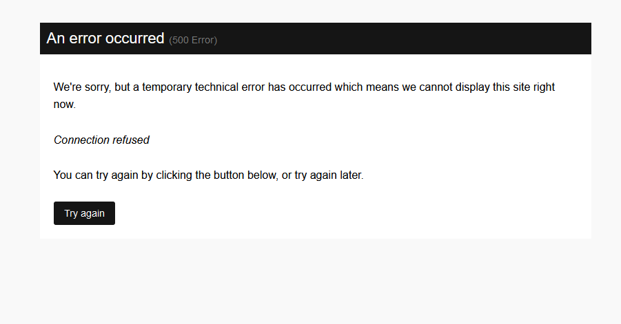
On 1/30/2022 at 10:06 PM, ssp said:
nowhere else for me to post but i keep getting site issues, anyone else getting this??

daily... have tok reload the side then it works
-
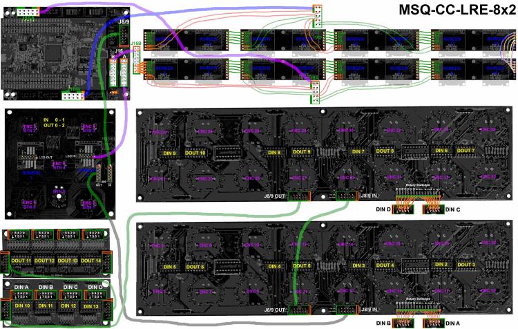
currently working on V2 (now with Displays), wiki and programming currently on development.... http://wiki.midibox.org/doku.php?id=msq-cc-lre-v2
much to programm... but it combines the last modules i designed - to get it into Eurorack...
-
http://wiki.midibox.org/doku.php?id=euro-aout-ng-connector-board
A Eurorack Connector Board and Frontpanel for the classic Aout-NG-PCB
-
u use custom code? or ng script? I dont have any knowledge of NG-Script nor offical apps... i program my own based on MIOS.
in my memory.... to get 8 additional only this is needet: (used in my filterbox - in my app.c in the init routine on startup....)
    // Set GPIO @ J10A
    for (x=0; x<16; ++x) {  // Turn on all PINS --- activate Bypass Relais ssm2044
    MIOS32_BOARD_J10_PinInit(x, MIOS32_BOARD_PIN_MODE_OUTPUT_PP); MIOS32_BOARD_J10_PinSet (x, 1); }

    // LCD
    xLCDSemaphore = xSemaphoreCreateRecursiveMutex();	    // create Mutex for LCD access
    MIOS32_LCD_DeviceSet(0);    MIOS32_LCD_Init(0);
    MIOS32_LCD_DeviceSet(1);    MIOS32_LCD_Init(0);
    MIOS32_LCD_DeviceSet(2);    MIOS32_LCD_Init(0);
    MIOS32_LCD_DeviceSet(3);    MIOS32_LCD_Init(0);
    MIOS32_LCD_DeviceSet(4);    MIOS32_LCD_Init(0);
    MIOS32_LCD_DeviceSet(5);    MIOS32_LCD_Init(0);
    MIOS32_LCD_DeviceSet(6);    MIOS32_LCD_Init(0);
    MIOS32_LCD_DeviceSet(7);    MIOS32_LCD_Init(0);
    MIOS32_LCD_DeviceSet(8);    MIOS32_LCD_Init(0);
    MIOS32_LCD_DeviceSet(9);    MIOS32_LCD_Init(0);
    MIOS32_LCD_DeviceSet(10);   MIOS32_LCD_Init(0);
    MIOS32_LCD_DeviceSet(11);   MIOS32_LCD_Init(0);
    MIOS32_LCD_DeviceSet(12);   MIOS32_LCD_Init(0);
    MIOS32_LCD_DeviceSet(13);   MIOS32_LCD_Init(0);
    MIOS32_LCD_DeviceSet(14);   MIOS32_LCD_Init(0);
    MIOS32_LCD_DeviceSet(15);   MIOS32_LCD_Init(0);
exotics:
example triggermatrix has 9 SSD1306 Displays so i needet one more the J15 can deliever the "Menue-LCD" ... my solution was to adapt the app_lcd.c (and .h) and includet it locally (in my project folder and changed the build path for it...)
Since i did not know what was going on, i reduce the code as much i can (deletet all not "universal" LCD code, all Rotated-Display - and non SSD1306 variants) - so i had the change to understand the "need to know" - i cant remember why i did it that way...dont ask - but maybe it helps
//	LCD driver for 9x SSD1306
// 		MIOS32_LCD environment variable set   to    "universal"
//		reduced by Michael Sigl

#include <mios32.h>
#include <glcd_font.h>
#include <string.h>
#include "app_lcd.h"


static unsigned long long display_available = 0;

static u8 prev_glcd_selection = 0xfe; // the previous mios32_lcd_device, 0xff: all CS were activated, 0xfe: will force the update


// pin initialisation >> Additonal CS-Line for the One MENUE-LCD
inline static s32 APP_LCD_ExtPort_Init(void) {

	MIOS32_BOARD_J10_PinInit(8, MIOS32_BOARD_PIN_MODE_OUTPUT_PP);
	return 0;
}


/////////////////////////////////////////////////////////////////////////////
// Initializes the CS pins for GLCDs with serial port
// - 8 CS lines are available at J15
// - additional lines are available J10
/////////////////////////////////////////////////////////////////////////////
static s32 APP_LCD_SERGLCD_CS_Init(void)	{

    APP_LCD_ExtPort_Init();

	int num_lcds = mios32_lcd_parameters.num_x * mios32_lcd_parameters.num_y;
	display_available |= (1 << num_lcds)-1;

  return 0; // no error
}


/////////////////////////////////////////////////////////////////////////////
// Sets the CS line of a serial GLCDs depending on mios32_lcd_device
// if "all" flag is set, commands are sent to all segments
/////////////////////////////////////////////////////////////////////////////
static s32 APP_LCD_SERGLCD_CS_Set(u8 value, u8 all)	{

    // Note: assume that CS lines are low-active!
    if( all ) {
			      if( prev_glcd_selection != 0xff ) {
														prev_glcd_selection = 0xff;
														MIOS32_BOARD_J15_DataSet(value ? 0x00 : 0xff);

														MIOS32_BOARD_J10_PinSet(8, value ? 0 : 1);

													 }
    } else {
      if( prev_glcd_selection != mios32_lcd_device ) {
	prev_glcd_selection = mios32_lcd_device;
	u32 mask = value ? ~(1 << mios32_lcd_device) : 0xffffffff;

	MIOS32_BOARD_J15_DataSet(mask);

	MIOS32_BOARD_J10_PinSet(8,  (mask >> (8)) & 1);
	}
    }


  return 0; // no error
}


/////////////////////////////////////////////////////////////////////////////
// Initializes application specific LCD driver
/////////////////////////////////////////////////////////////////////////////
s32 APP_LCD_Init(u32 mode)	{

		if( mios32_lcd_device >= 9 )	{ return -2; } // unsupported LCD device number

		// enable display by default
		display_available |= (1ULL << mios32_lcd_device);

		// the OLED works at 3.3V, level shifting (and open drain mode) not required
		if( MIOS32_BOARD_J15_PortInit(0) < 0 )	{ return -2; } // failed to initialize J15

		display_available |= 0xff;

		APP_LCD_SERGLCD_CS_Init(); // will also enhance display_available depending on total number of LCDs

		// wait 500 mS to ensure that the reset is released
		{
		int i;
		for(i=0; i<500; ++i)
		MIOS32_DELAY_Wait_uS(1000);
		}


		// initialize LCDs
		APP_LCD_Cmd(0xa8); // Set MUX Ratio
		APP_LCD_Cmd(0x3f);

		APP_LCD_Cmd(0xd3); // Set Display Offset
		APP_LCD_Cmd(0x00);

		APP_LCD_Cmd(0x40); // Set Display Start Line

		APP_LCD_Cmd(0xa1); // Set Segment re-map: rotated
		APP_LCD_Cmd(0xc8); // Set COM Output Scan Direction: rotated


		APP_LCD_Cmd(0xda); // Set COM Pins hardware configuration
		APP_LCD_Cmd(0x12);

		APP_LCD_Cmd(0x81); // Set Contrast Control
		APP_LCD_Cmd(0x7f); // middle

		APP_LCD_Cmd(0xa4); // Disable Entiere Display On

		APP_LCD_Cmd(0xa6); // Set Normal Display

		APP_LCD_Cmd(0xd5); // Set OSC Frequency
		APP_LCD_Cmd(0x80);

		APP_LCD_Cmd(0x8d); // Enable charge pump regulator
		APP_LCD_Cmd(0x14);

		APP_LCD_Cmd(0xaf); // Display On

		APP_LCD_Cmd(0x20); // Enable Page mode
		APP_LCD_Cmd(0x02);


  return (display_available & (1ULL << mios32_lcd_device)) ? 0 : -1; // return -1 if display not available
}


/////////////////////////////////////////////////////////////////////////////
// Sends data byte to LCD
// IN: data byte in <data>
// OUT: returns < 0 if display not available or timed out
/////////////////////////////////////////////////////////////////////////////
s32 APP_LCD_Data(u8 data) {

		// check if if display already has been disabled
		if( !(display_available & (1ULL << mios32_lcd_device)) )	{ return -1; }

		// chip select and DC
		APP_LCD_SERGLCD_CS_Set(1, 0);

		MIOS32_BOARD_J15_RS_Set(1); // RS pin used to control DC

		// send data
		MIOS32_BOARD_J15_SerDataShift(data);


		// increment graphical cursor
		++mios32_lcd_x;

		// if end of display segment reached: set X position of all segments to 0
		if( (mios32_lcd_x % mios32_lcd_parameters.width) == 0 ) {	APP_LCD_Cmd(0x00); // set X=0
																	APP_LCD_Cmd(0x10);	}
		return 0; // no error


		}


/////////////////////////////////////////////////////////////////////////////
// Sends command byte to LCD
// IN: command byte in <cmd>
/////////////////////////////////////////////////////////////////////////////
s32 APP_LCD_Cmd(u8 cmd)	{

		// check if if display already has been disabled
		if( !(display_available & (1ULL << mios32_lcd_device)) )	{ return -1; }

		// select all LCDs
		APP_LCD_SERGLCD_CS_Set(1, 1);

		MIOS32_BOARD_J15_RS_Set(0); // RS pin used to control DC

		MIOS32_BOARD_J15_SerDataShift(cmd);
		return 0;
}


/////////////////////////////////////////////////////////////////////////////
// Clear Screen
// IN: -
// OUT: returns < 0 on errors
/////////////////////////////////////////////////////////////////////////////
s32 APP_LCD_Clear(void)	{

    s32 error = 0;
    u8 x, y;

    // use default font
    MIOS32_LCD_FontInit((u8 *)GLCD_FONT_NORMAL);

    // send data
    for(y=0; y<mios32_lcd_parameters.height/8; ++y) {
      error |= MIOS32_LCD_CursorSet(0, y);

      // select all LCDs
      APP_LCD_SERGLCD_CS_Set(1, 1);

	MIOS32_BOARD_J15_RS_Set(1); // RS pin used to control DC

	for(x=0; x<mios32_lcd_parameters.width; ++x)
	  MIOS32_BOARD_J15_SerDataShift(0x00);

    }

    // set X=0, Y=0
    error |= MIOS32_LCD_CursorSet(0, 0);

    return error;
  }


/////////////////////////////////////////////////////////////////////////////
// Sets cursor to given position
/////////////////////////////////////////////////////////////////////////////
s32 APP_LCD_CursorSet(u16 column, u16 line)	{	return APP_LCD_GCursorSet(mios32_lcd_x, mios32_lcd_y);	}


/////////////////////////////////////////////////////////////////////////////
// Sets graphical cursor to given position
/////////////////////////////////////////////////////////////////////////////
s32 APP_LCD_GCursorSet(u16 x, u16 y)	{

    s32 error = 0;

    // set X position
    error |= APP_LCD_Cmd(0x00 | (x & 0xf));
    error |= APP_LCD_Cmd(0x10 | ((x>>4) & 0xf));

    // set Y position
    error |= APP_LCD_Cmd(0xb0 | ((y>>3) & 7));

    return error;
}


/////////////////////////////////////////////////////////////////////////////
// Initializes a single special character  // only for Character-LCDs
/////////////////////////////////////////////////////////////////////////////
s32 APP_LCD_SpecialCharInit(u8 num, u8 table[8])	{	return -3; }// not supported


/////////////////////////////////////////////////////////////////////////////
// Sets the background colour
// Only relevant for colour GLCDs
/////////////////////////////////////////////////////////////////////////////
s32 APP_LCD_BColourSet(u32 rgb) { return -3; }  // not supported


/////////////////////////////////////////////////////////////////////////////
// Sets the foreground colour
// Only relevant for colour GLCDs
/////////////////////////////////////////////////////////////////////////////
s32 APP_LCD_FColourSet(u32 rgb)	{ return -3; } // not supported


/////////////////////////////////////////////////////////////////////////////
// Sets a pixel in the bitmap
// IN: bitmap, x/y position and colour value (value range depends on APP_LCD_COLOUR_DEPTH)
/////////////////////////////////////////////////////////////////////////////
s32 APP_LCD_BitmapPixelSet(mios32_lcd_bitmap_t bitmap, u16 x, u16 y, u32 colour)	{
  if( x >= bitmap.width || y >= bitmap.height )
    return -1; // pixel is outside bitmap

  // all GLCDs support the same bitmap scrambling
  u8 *pixel = (u8 *)&bitmap.memory[bitmap.line_offset*(y / 8) + x];
  u8 mask = 1 << (y % 8);

  *pixel &= ~mask;
  if( colour )
    *pixel |= mask;

  return -3; // not supported
}


/////////////////////////////////////////////////////////////////////////////
// Transfers a Bitmap within given boundaries to the LCD
// IN: bitmap
/////////////////////////////////////////////////////////////////////////////
s32 APP_LCD_BitmapPrint(mios32_lcd_bitmap_t bitmap) {

  // abort if max. width reached
  if( mios32_lcd_x >= mios32_lcd_parameters.width )	{ return -2; }

  // all GLCDs support the same bitmap scrambling
  int line;
  int y_lines = (bitmap.height >> 3);

  u16 initial_x = mios32_lcd_x;
  u16 initial_y = mios32_lcd_y;
  for(line=0; line<y_lines; ++line) {

    // calculate pointer to bitmap line
    u8 *memory_ptr = bitmap.memory + line * bitmap.line_offset;

    // set graphical cursor after second line has reached
    if( line > 0 ) {
      mios32_lcd_x = initial_x;
      mios32_lcd_y += 8;
      APP_LCD_GCursorSet(mios32_lcd_x, mios32_lcd_y);
    }

    // transfer character
    int x;
    for(x=0; x<bitmap.width; ++x)
      APP_LCD_Data(*memory_ptr++);
  }

  // fix graphical cursor if more than one line has been print
  if( y_lines >= 1 ) {
    mios32_lcd_y = initial_y;
    APP_LCD_GCursorSet(mios32_lcd_x, mios32_lcd_y);
  }

  return 0; // no error
}
another example where i had to define CS pins, because i used Dipcore - with limitaded IO:
/*
 * fixed Hardcoded for 4x >>> SSD1306! > CV1 Project > DIPCORE F4!
 * ==========================================================================
 * Changed Version - Michael Sigl
 * ==========================================================================
 */
#include <mios32.h>
#include "glcd_font.h"
#include <string.h>
#include "app_lcd.h"

/////////////////////////////////////////////////////////////////////////////
// pin mapping
/////////////////////////////////////////////////////////////////////////////
#define SCLK_PORT      	GPIOD
#define SCLK_PIN       	GPIO_Pin_6

#define SER_PORT       	GPIOD        // used as DC (data/command select) for serial interfaces
#define SER_PIN        	GPIO_Pin_2

#define E1_PORT        	GPIOC        // used to control SCLK of serial interfaces
#define E1_PIN         	GPIO_Pin_1

#define E2_PORT        	GPIOC
#define E2_PIN         	GPIO_Pin_9

#define RW_PORT        	GPIOC        // used to control data output of serial interfaces
#define RW_PIN         	GPIO_Pin_12

#define CS1_PORT		GPIOB        // used to control SCLK of serial interfaces
#define CS1_PIN         GPIO_Pin_12

#define CS2_PORT        GPIOC
#define CS2_PIN         GPIO_Pin_0

#define CS3_PORT        GPIOC		// LED 0 - Extra CS-Line on Dipcore
#define CS3_PIN         GPIO_Pin_6

#define CS4_PORT        GPIOC		// LED 1 - Extra CS-Line on Dipcore
#define CS4_PIN         GPIO_Pin_7
// you could define here more CS PINS! but be sure to deactivate  the  "Orginal" function of it...


// following macros simplify the access to the pins
#define PIN_SER(b)  MIOS32_SYS_STM_PINSET(SER_PORT, SER_PIN, b)
#define PIN_E1(b)   MIOS32_SYS_STM_PINSET(E1_PORT, E1_PIN, b)

#define PIN_RW(b)   MIOS32_SYS_STM_PINSET(RW_PORT, RW_PIN, b)

#define PIN_CS1(b)   MIOS32_SYS_STM_PINSET(CS1_PORT, CS1_PIN, b)
#define PIN_CS2(b)   MIOS32_SYS_STM_PINSET(CS2_PORT, CS2_PIN, b)
#define PIN_CS3(b)   MIOS32_SYS_STM_PINSET(CS3_PORT, CS3_PIN, b)
#define PIN_CS4(b)   MIOS32_SYS_STM_PINSET(CS4_PORT, CS4_PIN, b)
// you could define here more CS PINS! but be sure to deactivate  the  "Orginal" function of it...


#define PIN_SERLCD_DATAOUT(b) MIOS32_SYS_STM_PINSET(RW_PORT, RW_PIN, b)

#define PIN_SERLCD_SCLK_0     { MIOS32_SYS_STM_PINSET_0(E1_PORT, E1_PIN); MIOS32_SYS_STM_PINSET_0(E2_PORT, E2_PIN); }
#define PIN_SERLCD_SCLK_1     { MIOS32_SYS_STM_PINSET_1(E1_PORT, E1_PIN); MIOS32_SYS_STM_PINSET_1(E2_PORT, E2_PIN); }

/// //////////////////////////////////////////////////////////////////////////////////////////////////////////////////

//////////////////////////////////////////////////////////////////////////
//	PINS for Additonl LCD 4 & 5 DIPCORE   if needet
//	MIOS32_SYS_STM_PINSET(GPIOC, GPIO_Pin_13, data & 1); // J10B.D8 = ser
//	MIOS32_SYS_STM_PINSET_0(GPIOC, GPIO_Pin_14); // J10B.D9 = 0 (Clk)
//////////////////////////////////////////////////////////////////////////


//
///////////////////////////////////////////////////////////////////////////////////////////////////////////
// Initializes the Ports/Pins (aka J15)  (which was once J15 in MIOS32_BOARD.c  but now integrated in this Program directly)
///////////////////////////////////////////////////////////////////////////////////////////////////////////
s32 PortInit(u32 mode) {

		// configure push-pull pins
		GPIO_InitTypeDef GPIO_InitStructure;
		GPIO_StructInit(&GPIO_InitStructure);

		GPIO_InitStructure.GPIO_Mode  = GPIO_Mode_OUT;
		GPIO_InitStructure.GPIO_OType = GPIO_OType_PP;
		GPIO_InitStructure.GPIO_Speed = GPIO_Speed_50MHz; // 25 is weak driver to reduce transients


		GPIO_InitStructure.GPIO_Pin = CS1_PIN;
		GPIO_Init(CS1_PORT, &GPIO_InitStructure);

		GPIO_InitStructure.GPIO_Pin = CS2_PIN;
		GPIO_Init(CS2_PORT, &GPIO_InitStructure);

		GPIO_InitStructure.GPIO_Pin = CS3_PIN;	// Extra CS-Lines
		GPIO_Init(CS3_PORT, &GPIO_InitStructure);

		GPIO_InitStructure.GPIO_Pin = CS4_PIN;	// Extra CS-Lines
		GPIO_Init(CS4_PORT, &GPIO_InitStructure);


		GPIO_InitStructure.GPIO_Pin = SER_PIN;
		GPIO_Init(SER_PORT, &GPIO_InitStructure);

		GPIO_InitStructure.GPIO_Pin = E1_PIN;
		GPIO_Init(E1_PORT, &GPIO_InitStructure);

		GPIO_InitStructure.GPIO_Pin = RW_PIN;
		GPIO_Init(RW_PORT, &GPIO_InitStructure);

		// Activate all CS Lines
		PIN_CS1(0);	// J15 CS1 Line
		PIN_CS2(0);	// J15 CS2 Line
		PIN_CS3(0);	// CS-Extra Line
		PIN_CS4(0);	// CS-Extra Line

		PIN_RW(0);
		PIN_E1(0);

		return 0; // no error
}


/////////////////////////////////////////////////////////////////////////////
// 	shift an 8bit data value to LCDs with serial interface
//! (SCLK connected to J15A:E, Data line connected to J15A:RW)
//! \param[in] data the 8bit value
/////////////////////////////////////////////////////////////////////////////
s32 SerDataShift(u8 data) {

  MIOS32_IRQ_Disable();

		  int i;
		  for(i=0; i<8; ++i, data <<= 1) {  PIN_SERLCD_DATAOUT(data & 0x80);
										    PIN_SERLCD_SCLK_0;
										    PIN_SERLCD_SCLK_0;
										    PIN_SERLCD_SCLK_1;
										    PIN_SERLCD_SCLK_1;
										  }
		  PIN_SERLCD_SCLK_0;
		  PIN_SERLCD_DATAOUT(0);

  MIOS32_IRQ_Enable();

  return 0; // no error
}


/////////////////////////////////////////////////////////////////////////////
// to set the RS pin
// \param[in] rs state of the RS pin
/////////////////////////////////////////////////////////////////////////////
s32 RS_Set(u8 rs) {	PIN_SER(rs);	return 0; }


/////////////////////////////////////////////////////////////////////////////
// Select a LCD  /  Select CS LINE
/////////////////////////////////////////////////////////////////////////////
static s32 APP_LCD_SERGLCD_CS_Set(u8 value, u8 all){

	// Activate ALL Screens @ once
	if( all ) {	PIN_CS1(0);
				PIN_CS2(0);
				PIN_CS3(0);
				PIN_CS4(0);	}

  else {	switch (mios32_lcd_device) {	case 0: PIN_CS1(0);			// the active Screen
													PIN_CS2(1);			// deactivate
													PIN_CS3(1);			// deactivate
													PIN_CS4(1); break;	// deactivate

											case 1: PIN_CS1(1);			// deactivate
													PIN_CS2(0);			// the active Screen
													PIN_CS3(1);			// deactivate
													PIN_CS4(1); break;	// deactivate

											case 2: PIN_CS1(1);			// deactivate
													PIN_CS2(1);			// deactivate
													PIN_CS3(0);			// the active Screen
													PIN_CS4(1); break;	// deactivate

											case 3: PIN_CS1(1);			// deactivate
													PIN_CS2(1);			// deactivate
													PIN_CS3(1);			// deactivate
													PIN_CS4(0); break;	// the active Screen
											break;
										}
		}
  return 0; // no error
}


/////////////////////////////////////////////////////////////////////////////
// Initializes LCD driver
/////////////////////////////////////////////////////////////////////////////
s32 APP_LCD_Init(u32 mode)	{

	        PortInit(0); // Init the Ports & Pins (aka J15 + extra CS-Pins)

	        // wait 500 mS to ensure that the reset is released
	        {
	          int i;
	          for(i=0; i<500; ++i)
	            MIOS32_DELAY_Wait_uS(1000);		}

	        // initialize LCDs
	        APP_LCD_Cmd(0xa8); // Set MUX Ratio
	        APP_LCD_Cmd(0x3f);

	        APP_LCD_Cmd(0xd3); // Set Display Offset
	        APP_LCD_Cmd(0x00);

	        APP_LCD_Cmd(0x40); // Set Display Start Line


			APP_LCD_Cmd(0xa1);	// Set Segment re-map: rotated
			APP_LCD_Cmd(0xc8); 	// Set COM Output Scan Direction: rotated

	        APP_LCD_Cmd(0xda); // Set COM Pins hardware configuration
	        APP_LCD_Cmd(0x12);

	        APP_LCD_Cmd(0x81); // Set Contrast Control
	        APP_LCD_Cmd(0x7f); // middle

	        APP_LCD_Cmd(0xa4); // Disable Entiere Display On

	        APP_LCD_Cmd(0xa6); // Set Normal Display

	        APP_LCD_Cmd(0xd5); // Set OSC Frequency
	        APP_LCD_Cmd(0x80);

	        APP_LCD_Cmd(0x8d); // Enable charge pump regulator
	        APP_LCD_Cmd(0x14);

	        APP_LCD_Cmd(0xaf); // Display On

	        APP_LCD_Cmd(0x20); // Enable Page mode
	        APP_LCD_Cmd(0x02);

	return 0;
}


/////////////////////////////////////////////////////////////////////////////
// Sends data byte to LCD
// IN: data byte in <data>
/////////////////////////////////////////////////////////////////////////////
s32 APP_LCD_Data(u8 data){

	APP_LCD_SERGLCD_CS_Set(1, 0);

	// RS pin used to control DC
	RS_Set(1);  //1: Data at D7 is treated as DISPLAY data,
				//   written to Graphic Display Ram (GDDRAM)
				//0: Data at D7:0 is transfaired to the command register - treated as command

	// send data
	SerDataShift(data);

	// increment graphical cursor
	++mios32_lcd_x;

	// if end of display segment reached: set X position of all segments to 0
	if( mios32_lcd_x  >= 128 ) {	APP_LCD_Cmd(0x00); // set X=0
									APP_LCD_Cmd(0x10);	}
	return 0; // no error
}

/////////////////////////////////////////////////////////////////////////////
// Sends data byte to LCD  --- Specially for Solid Oscilloscope Waves
// IN: data byte in <data>
/////////////////////////////////////////////////////////////////////////////
s32 APP_LCD_SCOPE(u8 h, u8 v, u8 pix){ // h=x, v=y, pix is 0 or 1 to activate a single pixel

	APP_LCD_SERGLCD_CS_Set(1, 0);

	//mios32_lcd_x = h;
	//mios32_lcd_y = v;

	// RS pin used to control DC
	RS_Set(1);
	// send data
	SerDataShift(pix);

	// increment graphical cursor
	// ++mios32_lcd_x;

	// if end of display segment reached: set X position of all segments to 0
	//if( (mios32_lcd_x % mios32_lcd_parameters.width) == 0 ) {	APP_LCD_Cmd(0x00); // set X=0
																//APP_LCD_Cmd(0x10);	}
	return 0; // no error
}

/////////////////////////////////////////////////////////////////////////////
// Sends command byte to LCD
// IN: command byte in <cmd>
// OUT: returns < 0 if display not available or timed out
/////////////////////////////////////////////////////////////////////////////
s32 APP_LCD_Cmd(u8 cmd){

		APP_LCD_SERGLCD_CS_Set(1, 1);	// select all LCDs

		RS_Set(0); 			// RS pin used to control DC
		SerDataShift(cmd);

		return 0;
}


/////////////////////////////////////////////////////////////////////////////
// Clear Screen
/////////////////////////////////////////////////////////////////////////////
s32 APP_LCD_Clear() {

		s32 error = 0;
		u8 x, y;

		// use default font
		MIOS32_LCD_FontInit((u8 *)GLCD_FONT_NORMAL);

		// select all LCDs
		APP_LCD_SERGLCD_CS_Set(1, 1);

		// send data
		for(y=0; y<mios32_lcd_parameters.height/8; ++y) {	error |= MIOS32_LCD_CursorSet(0, y);

												        RS_Set(1); // RS pin used to control DC
												        for(x=0; x<mios32_lcd_parameters.width; ++x)
												          SerDataShift(0x00);
												      }
		// set X=0, Y=0
		error |= MIOS32_LCD_CursorSet(0, 0);

		return 0;
}

/////////////////////////////////////////////////////////////////////////////
// Clear Screen --- Special Variant which clear only the current selected Screen
/////////////////////////////////////////////////////////////////////////////
s32 LCD_Clear(void) {

		s32 error = 0;
		u8 x, y;

		// Select the actually  Selected   LCD   ONLY!
		APP_LCD_SERGLCD_CS_Set(1, 0);

		// send data
		for(y=0; y<mios32_lcd_parameters.height/8; ++y) {	error |= MIOS32_LCD_CursorSet(0, y);

												        RS_Set(1); // RS pin used to control DC
												        for(x=0; x<mios32_lcd_parameters.width; ++x)
												          SerDataShift(0x00);
												      }
		// set X=0, Y=0
		error |= MIOS32_LCD_CursorSet(0, 0);
		return 0;
}

/////////////////////////////////////////////////////////////////////////////
// Sets cursor to given position
// IN: <column> and <line>
/////////////////////////////////////////////////////////////////////////////
s32 APP_LCD_CursorSet(u16 column, u16 line)  {
	// mios32_lcd_x/y set by MIOS32_LCD_CursorSet() function
	return APP_LCD_GCursorSet(mios32_lcd_x, mios32_lcd_y);
}


/////////////////////////////////////////////////////////////////////////////
// Sets graphical cursor to given position
// IN: <x> and <y>
// OUT: returns < 0 on errors
/////////////////////////////////////////////////////////////////////////////
s32 APP_LCD_GCursorSet(u16 x, u16 y){

      s32 error = 0;

      // set X position
      error |= APP_LCD_Cmd(0x00 | (x & 0xf));
      error |= APP_LCD_Cmd(0x10 | ((x>>4) & 0xf));

      // set Y position
      error |= APP_LCD_Cmd(0xb0 | ((y>>3) & 7));

      return error;
    }


/////////////////////////////////////////////////////////////////////////////
// Initializes a single special character
// IN: character number (0-7) in <num>, pattern in <table[8]>
// OUT: returns < 0 on errors
/////////////////////////////////////////////////////////////////////////////
s32 APP_LCD_SpecialCharInit(u8 num, u8 table[8]) {

    s32 i;

    // send character number
    APP_LCD_Cmd(((num&7)<<3) | 0x40);

    // send 8 data bytes
    for(i=0; i<8; ++i)	if( APP_LCD_Data(table[i]) < 0 )	return -1; // error during sending character

    // set cursor to original position
    return APP_LCD_CursorSet(mios32_lcd_column, mios32_lcd_line);
}


/////////////////////////////////////////////////////////////////////////////
// Sets the background colour
// Only relevant for colour GLCDs
/////////////////////////////////////////////////////////////////////////////
s32 APP_LCD_BColourSet(u32 rgb) {	return -3; }// not supported


/////////////////////////////////////////////////////////////////////////////
// Sets the foreground colour
// Only relevant for colour GLCDs
/////////////////////////////////////////////////////////////////////////////
s32 APP_LCD_FColourSet(u32 rgb) { return -3;  }// not supported


/////////////////////////////////////////////////////////////////////////////
// Sets a pixel in the bitmap
// IN: bitmap, x/y position and colour value (value range depends on APP_LCD_COLOUR_DEPTH)
// OUT: returns < 0 on errors
/////////////////////////////////////////////////////////////////////////////
s32 APP_LCD_BitmapPixelSet(mios32_lcd_bitmap_t bitmap, u16 x, u16 y, u32 colour) {

  if( x >= bitmap.width || y >= bitmap.height ) return -1; // pixel is outside bitmap

  // all GLCDs support the same bitmap scrambling
  u8 *pixel = (u8 *)&bitmap.memory[bitmap.line_offset*(y / 8) + x];
  u8 mask = 1 << (y % 8);

  *pixel &= ~mask;
  if( colour )
    *pixel |= mask;

  return -3; // not supported
}


/////////////////////////////////////////////////////////////////////////////
// Transfers a Bitmap within given boundaries to the LCD
// IN: bitmap
// OUT: returns < 0 on errors
/////////////////////////////////////////////////////////////////////////////
s32 APP_LCD_BitmapPrint(mios32_lcd_bitmap_t bitmap){

  // abort if max. width reached
  if( mios32_lcd_x >= mios32_lcd_parameters.width ) return -2;

  // all GLCDs support the same bitmap scrambling
  int line;
  int y_lines = (bitmap.height >> 3);

  u16 initial_x = mios32_lcd_x;
  u16 initial_y = mios32_lcd_y;
  for(line=0; line<y_lines; ++line) {	// calculate pointer to bitmap line
									    u8 *memory_ptr = bitmap.memory + line * bitmap.line_offset;

									    // set graphical cursor after second line has reached
									    if( line > 0 ) {	mios32_lcd_x = initial_x;
															mios32_lcd_y += 8;
															APP_LCD_GCursorSet(mios32_lcd_x, mios32_lcd_y);
														}
									    // transfer character
									    int x;
									    for(x=0; x<bitmap.width; ++x)	APP_LCD_Data(*memory_ptr++);
									 }

  // fix graphical cursor if more than one line has been print
  if( y_lines >= 1 ) {	mios32_lcd_y = initial_y;
						APP_LCD_GCursorSet(mios32_lcd_x, mios32_lcd_y); }

  return 0; // no error
}
-
ok kenn mich aus... das panel wird erst entworfen
natürlich möglich ist so wie ich das sehe ist das einfach ein http://www.ucapps.de/mbhp_midi_io.html
nur halt 2 auf einer platine
die line driver von midiphy kannst auch verwenden (obwohl ich einen da hätte den ich nicht mehr brauche - weil ich zwei habe)
vom midiphy core her weis i ned- müsste pin compatibel zum Discovery Board sein. - aber das orginal könntest auch von mir haben. http://www.ucapps.de/mbhp_core_stm32f4.html
da wäre halt sd slot und usb gleich auf einem board... musst selber nachmessen was von der größe her eher in dein Wunschgehäuse und Anschluss Panel passt.
@ gate: direkt aus dem gehäuse... ja entweder via Linedriver für extern - oder via DINX4 intern http://www.ucapps.de/mbhp_din.html
oder du baust dir https://www.midiphy.com/en/shop-details/121/50/seq-v4-eurorack-modules-essential-kit-midiphy-seq-v4-eurorack-modular-midi-cv-interface
direkt ins gehäuse.
für CV eben auch das midiphy module, oder halt. http://www.midibox.org/dokuwiki/aout_ng und dann verkabeln zu buchsen ihrgendwo im gehäuse
(da hät ich was daheim falls die auflösung für dich reicht)
in beiden fällen brauchst halt dann im sequencer die +-12V um das CV von 3V raufzuskalieren zu verwendbaren werten...
-
tirol... oberösterreich - ok englisch ist nicht dein ding -
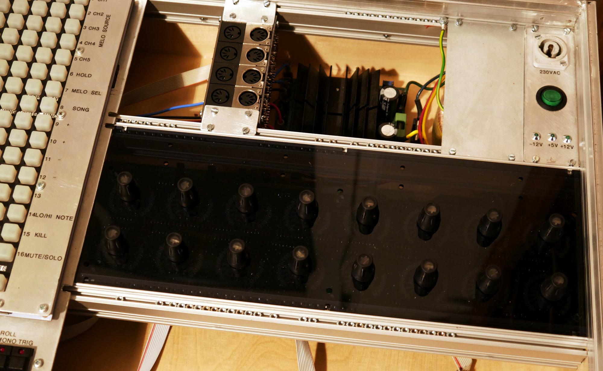
guad ich will doch nur die Anschlussblende sehen aka Backpanel
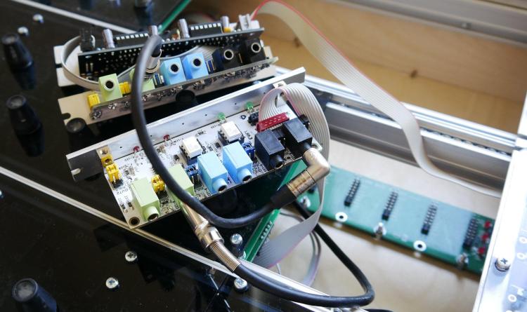
diese Rückansicht z.B.
ist für ein core stm32F4... und ist offensichtlich für 2x Midi IO Module geschaffen
für diese ausführung hätte ich alles daheim, bis auf das zweite MIDI IO...
-
nope that is a plastic case made by ponoko... so why you dont post the panel - else i am out!
why you want to use the midiphy core? use the orginal core? I ask because i have booth at home the lpc17 core (need different packbanel) the stm32F4 core '(need different backpanel)... the orginal stm32F4 core use the same microcontroller on a different developement board - like the waveshare from midiphy... ... i too have the linedriver pcb... i have a whole midibox labor with assembled modules at home - but if you wont show the backpanel - i cant help you anyway...
-
nope i cant find it - this is only the frontpanel.
i need too see your backpanel - aka the housing aka the aluminium plate for the connections... - about software: there is still a firmware for 4.096 so yes possible...
-
show me the connection panel of the device - so i see for what Core - Line-Trans it is build for...
-
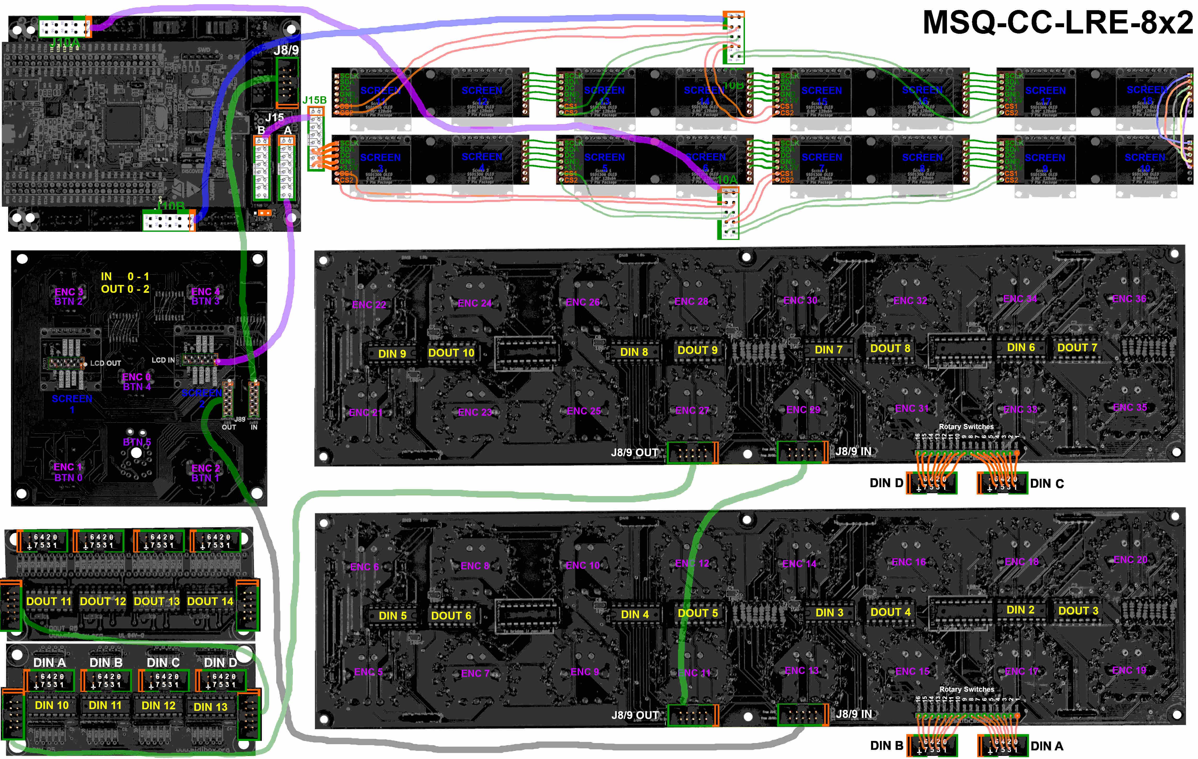
@latigid on http://www.midibox.org/dokuwiki/doku.php?id=display_driver
i have 2 off your boards assambled, right now i need 18x SSD1306 in my project,
but the wiki is a bit rare about how to connect the displays from there - I would expand a "how to connect Oleds to the board" if you explain it to me. thx!
-mike
-

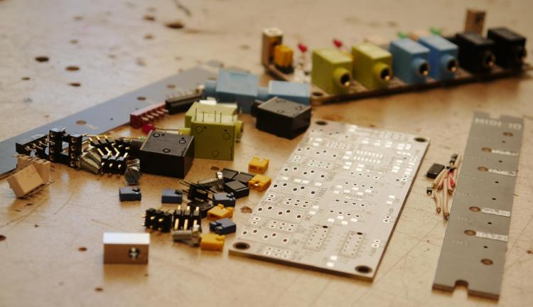
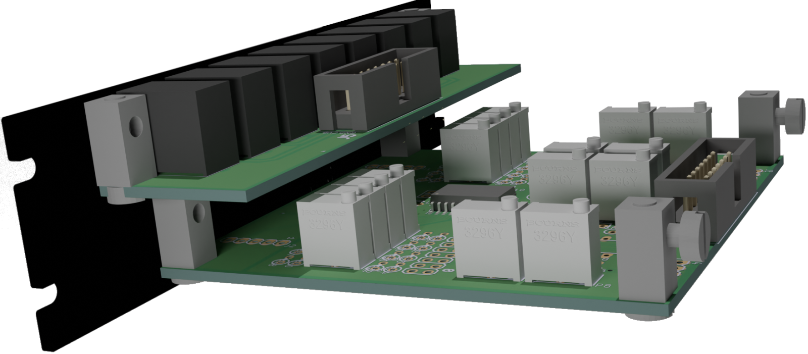
Made a wiki Euro-Midi-IO
Frontpanel and PCBs are ordered -l now wait for the prototype
can someone check the shematic - i may overlooked something:
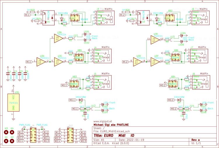
Thx.
-
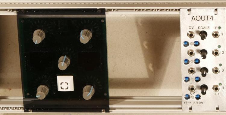
this time with the Matias-Switches known from the Midiphy Projects.
And the Acrylic Frontplate made by formulor.
-
@monokinetic I have ordered 5 Boards. 4 I need. 1 then left (1 board is for one LRE8x2) --- if you need more - or you are not in the EU, you know where to find the gerbers ;) and where to get the real cheap, but i suggest to wait untill i testet them.
still waiting for the PCBs (10-12 to ship...) - so 2 weeks or so there will be an update - if everything is right...
but i got the Acrylic Frontplate, and it fits for the LRE8x2... but the mounting holes for it are not necessery - because the Encoders hold the PCB

so the End version of the plate will not have this Holes.
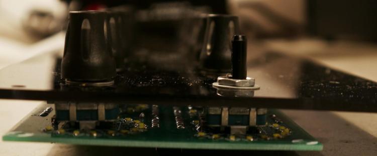
the Alps (SIDstyle) Buttons hold nice, and the travel for the inbuilt encoder-buttons are working - so there is no need to remove the Encoders "Noses"
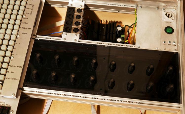
I have made a huge eurorack, so no space problems there... and of course the Panel fits (i let some Air for production)
-
currently untestet concept for a eurorack panel for the caseless LoopA.
-


MBCV v2.01 alternative concept
in MIDIfication
Posted
i am on work the last years, on my own midibox CV- project... since i am a one man show, and there are a lot of projects running in paralell - and money is aviable only all "holy times"... it is not finished, and will not be in near future, but it will be in far future, since it is a core thing in my setup. (since i am on the way to modular...)
http://wiki.midibox.org/doku.php?id=cv1
it has not much to do with a NG, or MB-CV2... but it is a CV-Envelope Generator, Recorder and Looper, LFO, and Mixer, and the future goel is to have one UI that remotes a lot of Core-Modules which are connected to independend Midibox-AOUT-Modules, so you could use One to build up a complete midified (so you can save and load presets) Analog-Synthesizer - a drumsynth for example, and multiply that by for example by 8 so you have a 8part Drumsynth with one UI - so you save space in your eurorack...
how ever not finished - if interestd follow this topic: