

Phatline
-
Posts
1,285 -
Joined
-
Last visited
-
Days Won
72
Content Type
Profiles
Forums
Blogs
Gallery
Posts posted by Phatline
-
-
very cool!
tomorrow i will order such a display, the rest i have @ home.
dont miss understand that as "auftrag" i write down my needings, and my idea, i need some simular device, and maybe the ideas which came up can bring us forward a bit...
I am thinking about to built that the device in a 19" case, with midi conection to my already built footboard (with virtual buttons and displays and so on....) - fully controllable over the 19" case, and via midi the most interesting record and loop features in a jam situation e.g. Start Stop Loops, Record Loops, changing Loop length (offset/shift, length)
yes the "always record mode"... i told my guitarist about that, and he was not very family with the idea, to always record, and then when he thougt it was good to press record and it was done >>> i think he learned it about the old way -press record, press stop > and now he cant think that there is a better way "was der bauer nicht kennt frisst er nicht..." - for me as a human that want to express my self ONCE - and once it is done i will express me a other way - because otherwhise it would be boring... ok for me as a ONCE-Man i want to express the holy vibration once - and in this moment it is perfect! (oh it is always the first time you press on a keyboard...) the Machine have to capture this moment and have to loop that moment over and over over - while my guitarist want to repeat and repeat and repeat it ever and ever he says that is ReProducing-ability or something... i think just make that the device and say "PLAY!"
i thougt about the idea the last years... and there came out a few designs..
-1 Button - Move all the data in a cycle reward - it make sense to install some scroll mechanism - e.g. longer press automatic continue the shifting stepwise
+1 Button - Move all the data in a cycle forward - --//-- --//-- - maybe other technologies have to be used - IR-Transistors and LED-Arrays....
when you have just pressed the Always Recording-Button , you use normally the +1 button to shift the last recordet notes to the start of the loop... and a loop is long maybe something aroung 512 (in steps) so it is generally not hearable... the last recordet notes generally are not played good, because you was focused to find the RECord button and press it... maybe a automatic mode with a standard +Offset that is triggerd with the REC-Button is a solution,
how much steps (3 4 6 8...) automatic offset? > that is a user definied question and depends on how fast can a musican act, and how far are the ways to the Record Buttons... so it has to be changed via the Display-Menue.
Yes and of course -16 and + 16 Buttons (in 3er Mode these are automaticly -12 +12) Buttons which change the loop length
thinkable extra buttons parallel to the -16 +16 Buttons would be "doubled Length" Buttons which change by the first step -32, - 64, -128, -256, -512
just to jump faster to the "right" positions - and as nice side effect - when you always use this "doubled Length" buttons the 4 Loops are always in "Sync" >>> a 48 step loop and a 64 steps are always shifting around, in its endless loopness.... a 64 length loop and a 128 length loop will always play stable in the same playing to gether ---- maybe by playing mono-lead or bass sounds it does not matter, but when you play rich cords with half tones and full tones.... and on the other loop also...you can think there are moments when it sounds not so good.
-
this is realtime record - no step based... but the length - i think - is step-counted (miditicks)?
if the 4 LEDs are showing this - i think it is counting in 4er...8 16 32 64
my quest: it would be nice if i could choose un-straight counting like 3er, 6er 12er... (the setupd- counter structure is saved in the song, if the song is 3er based all 4 loops in this songs are 3er based)
my synth-guitarist alwasys ask me to make un-straight beats... with my korg er1 it is possible...it just counts to 12 instead to 16...... in with his RC300 of course also 3er are possible... and i must say after one year playing with him i - am in love with 3er...
-
maybe... i got mine long time ago
-
Idea:
it is inpired by the work of Andreas Körber and his "WortKraftSchwingung"Input: Midi notes
Output1: DMX R-G-B values
Destination1: RGBW-LED-PAR.
Output2: LFO Audio Output 4 Bodyshacker
a standart audio setup with a Midi-Sound-Synthesizer which is tuned to a specific frequency, a=430-445hz
this tuning has to be set in the Converter-Software, because the converter gets only notes not frequencys...
Hardware:
switched to STM32F4Stairville LEDPAR36 - RGBW-LED-PARConverting Idea:
is to octave the sound frequency as long we see it... since all octaves are sounding great...and some greater...the visible frequency then maybe also...and anyway - its a cool effect on stage.
so what has to be calculated?
we have hearable-sound-frequency in Herz [hz]
we want to calculate the Visible color frequency in NanoMeter [nm]
for example:
1. a note produce a sound of 100hz:
float midi[127] = {}; //represent Midinote 0-127 - and its value is a Frequency in [hz]
u32 actualnote = 69; // where 69 is A3 named A (which is tuned with "tuning" Variable above)
s32 notecount = 0; // only a counter variable to calculate the note frequencys.
float tuning = 431; //represent the tuning of "Kammerton A3"

for (notecount = 0; notecount < 127; ++notecount) //calculte all 127 notes and frequencys
{midi[notecount] = tuning * pow(2, (float)(notecount - 69)/12);}

midi[actualnote] ///(=outputs the Frequency in [hz] for the actual played note
2. calculate the visible octave of 100hz& divide lightspeed by that frequency
(hz*42th octave) / 10^12 =THz >>>> (100hz*2^42)/10^12 = 439.804THz
lightspeed/THz=nm >>>> 299792,458/439.804 = 681.640nm
float nm;
long thz;

thz = ( (midi[actualnote] * pow(2, 42) ) / 1000000000000);
nm = 299792.458 / (float)thz;
is the result not in the visible Spectrum > not between 790 and 390nm? whats then?:::
i figured out that D2-D3 is the visible octave (midi nr 42 - 54)
@431hz A3 tuning:
F2=753nm, F3=376nm
is it under 42?
+12 notes until it is above or equal F2, how many octaves?>how many change the whithe LED-Level....
is it above 53?
-12 notes until it is under or equal F3, how many octaves?>how many change the whithe LED-Level....:::
     //transpose the note to the visible Octave (NoteNr41-53) and save the octave Nr for further LED-White Parameters.
     octaveCOUNT = 4; //4 is the visible octave
     visiblenote = midinote;
     if (midinote < 42) {visiblenote = midinote + 12; --octaveCOUNT; // below visible octave?
         if (visiblenote < 42) {visiblenote = visiblenote + 12; --octaveCOUNT;
             if (visiblenote < 42) {visiblenote = visiblenote + 12; --octaveCOUNT;
                 if (visiblenote < 42) {visiblenote = visiblenote + 12; --octaveCOUNT; }}}}

     if (midinote > 54) {visiblenote = midinote - 12; ++octaveCOUNT; //above visible octave
         if (visiblenote > 54) {visiblenote = visiblenote - 12; ++octaveCOUNT;
             if (visiblenote > 54) {visiblenote = visiblenote - 12; ++octaveCOUNT;
                 if (visiblenote > 54) {visiblenote = visiblenote - 12; ++octaveCOUNT;
                     if (visiblenote > 54) {visiblenote = visiblenote - 12; ++octaveCOUNT;
                         if (visiblenote > 54) {visiblenote = visiblenote - 12; ++octaveCOUNT;}}}}}}
3. RGBW Calculation
no matter which we use i have to offset the code with the real world the "RGB-LED-Spot"
we cant speak of a exact octaved visible Light colour... but maybe we fade in a range +-hz
so your mind find the correct colour itself....like a detuned unisono synth---there are frequencys sometimes that sounds great...
the other thing is: Frequencys below 400 are UV... a UV-LED-DMX light would do the job... maybe i get me one once the dam DMX-Code thing is done.
//MIX WHITE Light to the RGB, by using the Octaves, you may turn of that feature if you dont want.
      if      (octaveCOUNT == 0) {RGBWnm[3] =   0;}
      else if (octaveCOUNT == 1) {RGBWnm[3] =  28;}
      else if (octaveCOUNT == 2) {RGBWnm[3] =  57;}
      else if (octaveCOUNT == 3) {RGBWnm[3] =  85;}
      else if (octaveCOUNT == 4) {RGBWnm[3] = 110;}
      else if (octaveCOUNT == 5) {RGBWnm[3] = 138;}
      else if (octaveCOUNT == 6) {RGBWnm[3] = 166;}
      else if (octaveCOUNT == 7) {RGBWnm[3] = 194;}
      else if (octaveCOUNT == 8) {RGBWnm[3] = 222;}
      else if (octaveCOUNT >= 9) {RGBWnm[3] = 255;}
      //WHITE OFFSET:
      RGBWdmx[3] = RGBWnm[3] -(RGBWenc[3]) ;


      //convert [nm] 2 [RGB] --- the GAMMA is not calculatet so - the colors @ end of spectrum are static...but they
      //have to fade out....
      if      (nm < 380) {RGBWnm[0] = 0;    //if it is no visible spectrum
                          RGBWnm[1] = 0;
                          RGBWnm[2] = 12;}  //a UV-Source has alternativly to be activated

      if      (nm > 780) {RGBWnm[0] = 12;   //a IR source has alternativly to be activated
                          RGBWnm[1] = 0;
                          RGBWnm[2] = 0;}

      else if (nm >= 380 && nm < 440) {RGBWnm[0] = ((-(nm - 440.) / (440. - 380.))*255);
                                       RGBWnm[1] = 0;
                                       RGBWnm[2] = 255;}

      else if (nm >= 440 && nm < 490) {RGBWnm[0] = 0;
                                       RGBWnm[1] = (( (nm - 440.) / (490. - 440.))*255);
                                       RGBWnm[2] = 255;}

      else if (nm >= 490 && nm < 510) {RGBWnm[0] = 0;
                                       RGBWnm[1] = 255;
                                       RGBWnm[2] = ((-(nm - 510.) / (510. - 490.))*255); }

      else if (nm >= 510 && nm < 580) {RGBWnm[0] = (( (nm - 510.) / (580. - 510.))*255);
                                       RGBWnm[1] = 255;
                                       RGBWnm[2] = 0;}
      else if (nm >= 580 && nm < 645) {RGBWnm[0] = 255;
                                       RGBWnm[1] = ((-(nm - 645.) / (645. - 580.))*255);
                                       RGBWnm[2] = 0;}

      else if (nm >= 645 && nm < 780) {RGBWnm[0] = 255;
                                       RGBWnm[1] = 0;
                                       RGBWnm[2] = 0;}
        }
}
4. Sending DMX Values
when we have the RGB-Values we send it via DMX to a RGB-LED, by adapting this code:
http://svnmios.midibox.org/listing.php?repname=svn.mios32&path=%2Ftrunk%2Fapps%2Fexamples%2Fdmx%2F
& studying this code:
http://svnmios.midibox.org/filedetails.php?repname=svn.mios32&path=%2Ftrunk%2Fmodules%2Fdmx%2Fdmx.c
void APP_Background(void){
//DMX:
  // endless loop
  while(1) { for (count=0;count<4;count++)
             { if (RGBWdmx[count]!=RGBWenc[count]) //if something has changed - send the value via DMX!
               {   RGBWdmx[count]=RGBWenc[count];
                   DMX_SetChannel(count,(u8)RGBWdmx[count]);}
		     }
           }
}
that was not the complicated thing... the complicatect comes now!
-
Change Master tune possible?
(MB6582 V2)
-
hmmm... the timer or the shiftregister update are not working as i want... i want a stable blink...instead, it sometimes some blinks dont accour... it looks like the counter overlaps with the shiftregister update or so...maybe it is a priority question --- any idea?
here is the code: (attached is also the full project - it runs on a lp17 core with dio-shiftregisters connected-dout register 1 pin 0 is the blink-output... the din register 1 pin 0+1 = hz-encoder.... the used display is 2x40 signs...)
#include <mios32.h> #include <FreeRTOS.h> #include <task.h> #include "tasks.h" #include "file.h" #include "app.h" #include <portmacro.h> #include <queue.h> #include <semphr.h> #include <string.h> #include "mios32_timer.h" #define NUM_ENCODERS 9 //5 Menue Encoders are connectet const mios32_enc_config_t encoders[NUM_ENCODERS] = {//(SR begin with 1, ENC with 0) // setup the Pinout of that Encoders { .cfg.type=DETENTED2, .cfg.speed=FAST, .cfg.speed_par=4, .cfg.sr=1, .cfg.pos=0 }, //Menue Encoder 0 - only virtual, since they are mapped to differnt Variables... { .cfg.type=DETENTED2, .cfg.speed=FAST, .cfg.speed_par=4, .cfg.sr=1, .cfg.pos=2 }, //Menue Encoder 1 - ...if "Menue Page Encoder" has changed { .cfg.type=DETENTED2, .cfg.speed=FAST, .cfg.speed_par=4, .cfg.sr=1, .cfg.pos=4 }, //Menue Encoder 2 { .cfg.type=DETENTED2, .cfg.speed=FAST, .cfg.speed_par=4, .cfg.sr=1, .cfg.pos=6 }, //Menue Encoder 3 { .cfg.type=DETENTED2, .cfg.speed=FAST, .cfg.speed_par=4, .cfg.sr=2, .cfg.pos=0 }, //Menue Encoder 4 { .cfg.type=DETENTED2, .cfg.speed=FAST, .cfg.speed_par=4, .cfg.sr=2, .cfg.pos=2 }, //Menue Encoder 5 { .cfg.type=DETENTED2, .cfg.speed=FAST, .cfg.speed_par=4, .cfg.sr=2, .cfg.pos=4 }, //Menue Encoder 6 { .cfg.type=DETENTED2, .cfg.speed=FAST, .cfg.speed_par=4, .cfg.sr=2, .cfg.pos=6 }, //Menue Encoder 7 { .cfg.type=DETENTED2, .cfg.speed=FAST, .cfg.speed_par=4, .cfg.sr=3, .cfg.pos=0 },}; //Menue Page Encoder xSemaphoreHandle xLCDSemaphore; // take and give access to LCD u32 MenueUpdateCount = 0; u32 value = 0; //Encoder calculation... u32 i = 0; //Encoder calcualtion //WKS u32 hz = 428; u32 nm = 10; u32 rpm = 25680; u32 time = 2161; //setup timer time u32 timecount = 0; u32 hzcount = 0; u32 decaytime = 128; //Task Prioritys #define MUTEX_LCD_TAKE { while( xSemaphoreTakeRecursive(xLCDSemaphore, (portTickType)0) != pdTRUE ); } //a Mutex reserve a Resoure (LCD or SD-Card) for a task, until it is given away... #define MUTEX_LCD_GIVE { xSemaphoreGiveRecursive(xLCDSemaphore); } #define PRIORITY_StoreLoad ( tskIDLE_PRIORITY + 2 ) //3:Mios standart static void StoreLoad(u8 tick, u16 order); static void Timer(void); void APP_Init(void){ MIOS32_BOARD_LED_Init(0xffffffff); //initialize all LEDs xLCDSemaphore = xSemaphoreCreateRecursiveMutex(); //create Mutex for LCD access //initialize encoders i = counter for(i=0; i<NUM_ENCODERS; ++i) MIOS32_ENC_ConfigSet(i, encoders[i]); //initialize encoders MIOS32_TIMER_Init(1, 1, Timer, MIOS32_IRQ_PRIO_HIGH); //1uS Timer set MIOS32_SRIO_ScanNumSet(1); // limit the number of DIN/DOUT SRs which will be scanned for faster scan rate //speed up SPI transfer rate (was MIOS32_SPI_PRESCALER_128, initialized by MIOS32_SRIO_Init()) MIOS32_SPI_TransferModeInit(MIOS32_SRIO_SPI, MIOS32_SPI_MODE_CLK1_PHASE1, MIOS32_SPI_PRESCALER_64); // prescaler 64 results into a transfer rate of 1 uS per bit // when 2 SRs are transfered, we are able to scan the whole 16x8 matrix in 300 uS } void Timer(){ timecount = timecount + 1; if (timecount > time) {MIOS32_DOUT_PinSet( 0, 1); timecount = 0;} if (timecount > decaytime) {MIOS32_DOUT_PinSet( 0, 0);}} void APP_Background(void){} void APP_Tick(void) { //1ms Event Triggering MenueUpdateCount = MenueUpdateCount + 1; if(MenueUpdateCount > 650){MenueUpdateCount = 0; StoreLoad(0, 0);}} //update the Menue void APP_MIDI_Tick(void){} void APP_MIDI_NotifyPackage(mios32_midi_port_t port, mios32_midi_package_t midi_package){} void APP_SRIO_ServicePrepare(void){} void APP_SRIO_ServiceFinish(void){} void APP_DIN_NotifyToggle(u32 pin, u32 pin_value){} void APP_ENC_NotifyChange(u32 encoder, s32 incrementer){ if(encoder == 0){ value = hz + incrementer; // increment to virtual position and ensure that the value is in range 0..127 if(value < 0) {value = 999;} if(value > 999){value = 0;} hz = value; time = 1000000/hz; //we count in mikro Sekonds! rpm = hz * 60; } if(encoder == 2){ value = time + incrementer; // increment to virtual position and ensure that the value is in range 0..127 if(value < 0) {value = 3000;} if(value > 3000){value = 0;} time = value; hz = 1000000/time; rpm = hz * 60; } if(encoder == 4){ value = rpm + incrementer; // increment to virtual position and ensure that the value is in range 0..127 if(value < 0) {value = 100000;} if(value > 100000){value = 0;} rpm = value; hz = rpm / 60; time = 1000000/hz; } if(encoder == 7){ value = (incrementer * 2) + decaytime; // increment to virtual position and ensure that the value is in range 0..127 if(value < 0) {value = 99999;} if(value > 99999){value = 0;} decaytime = value; } } void APP_AIN_NotifyChange(u32 pin, u32 pin_value){ //AIN - - Potentiometer has mooved - - Analog InPut } static void StoreLoad(u8 tick, u16 order){ //Display MENUE, Store+Load Bank & Sys-Config if(tick == 0){//Menue MUTEX_LCD_TAKE; //request LCD access MIOS32_LCD_Clear(); //clear screen //1st Line = Encoder Variables....change something! MIOS32_LCD_CursorSet(0, 0); MIOS32_LCD_PrintFormattedString("%d", hz); MIOS32_LCD_CursorSet(10, 0); MIOS32_LCD_PrintFormattedString("%d", time); MIOS32_LCD_CursorSet(20, 0); MIOS32_LCD_PrintFormattedString("%d", rpm); MIOS32_LCD_CursorSet(35, 0); MIOS32_LCD_PrintFormattedString("%d", decaytime); //2nd Line = Menue Describtio MIOS32_LCD_CursorSet(0, 1); MIOS32_LCD_PrintFormattedString("%s", "hz"); MIOS32_LCD_CursorSet(10, 1); MIOS32_LCD_PrintFormattedString("%s", "usec"); MIOS32_LCD_CursorSet(20, 1); MIOS32_LCD_PrintFormattedString("%s", "rpm"); MIOS32_LCD_CursorSet(35, 1); MIOS32_LCD_PrintFormattedString("%s", "decay"); MUTEX_LCD_GIVE;}} // release LCD access for other tasks -
I also need a Loopa for my Synth-Guitarist... also realtime recording... and no need for edit and so on... (he is able to play it again if it was no good recording... while i cant...)
YESS!!! > http://svnmios.midibox.org/listing.php?repname=svn.mios32&path=%2Fplayground%2Fhawkeye%2Fmbloopa%2F
thankz for that, this could make it easier to adapt it to my guitarist whises (the whole seq4 is to complex for me...)
(ich brauch so ein teil schon seit dezember...zeitmangel, motivationsmangel, trägheit, und Komplexität vom SEQ4 und trozdem... und schwups die wups - ein paar monate später- gibts so ein Teil - Hoch Lebe DIY Open Source Kooperation und der Erfindungsgeist)
-
i want the to adjust the exact RPM of my Blender (up to 37500 rpm)
via a menu encoder i want to setup the exact hz,
the code displays then the RPM value,
the leds connected to a dout-module begin to flash
the combinations of different Dout-pins to one LED give the led more Current... dont know up to know... maybe i need this.
i now have to adjust the speed off the blender until the rotor seems to not moving anymore

some basics?
if (RPM==Blinkfrequency) {there will be No Motion}
RPM=Rotation per minute
1minute has 60000ms
RPms=Rotation per ms
1RPM is 60000RPms
38000RPM is 2280000000RPms
u32 range is=4294967295
1hz = 60RPM
38000RPM = 633Hz so the maximal range of this strobo will be arround 640hz
Frequency=1/Time
Time=1/Frequency
1000hz = 1ms
the protone resonance frequency of hydrogen (H) = 61779498184847720448 Hz
the 58 Octave from this is 428.681 Hz
taken from the free m.rauch software: http://aladin24.de/htm/res/index.php
428,681hz = 25720,86 RPM --- this is the speed i want to setup the mixer with water in it.
Time= 1/428,681hz = 0,002161316s x 1000 = 2.1613ms
that meens that
void APP_Tick(void)is not accorate for this, since it is called evy 1ms
the standart updaterate ot the
void APP_SRIO_ServicePrepare(void){ //called before the shift register chain is scanned
MIOS32_DOUT_PinSet( 0, LEDvalue[0]);}
is 1,28uS which is accourate enough to handle the LED-Status
u32=4294.967.295 wordlength.
seco.milis.mikro I think thats enough
so set up a timer @1uS rate:
void APP_Init(void){ //initialize
    MIOS32_TIMER_Init(1, 1, Timer, MIOS32_IRQ_PRIO_LOW); //1uS Timer set
then count (timecount) to a specific time... when reached: reset the counter, turn on the led...
the counter now counts again a specific time until it reaches the decay--time-mark (here 100uS) now it turn off the LEDs
...now it counts forwarde to the specific time...reset the counter, turn on the led....
void Timer(){
timecount = timecount + 1;
if (timecount >= time) {LEDvalue[0] = 1; timecount = 0;}
if (timecount >= decaytime) {LEDvalue[0] = 0;}}
next time some menus, encoders, display, and formulars...
for what a ocataved protone resonancy frequency on water? hmm someone sayed that on this frequency the temperature drifts down and water got lost... i want to proove that!
-
NICE!!!
-
Live-Arrangment:
AbletonLive=Mixer und MelodyLoops
Korg Electribe Rythm MKII = Drumsynthesizer and Triggersource
Triggermatrix=Midiprocessere which take the MelodyLoop and save it, until the a Trigger accours - then it sends the melodys to the synths....
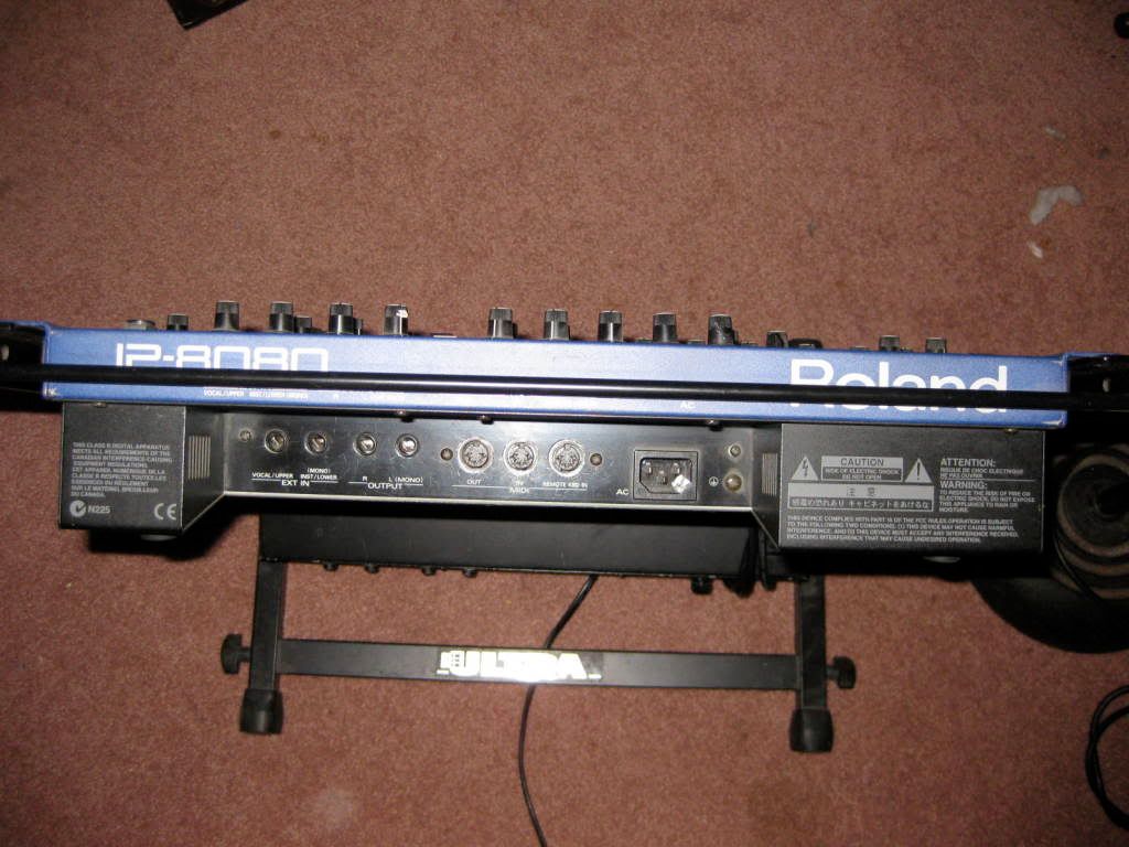
Synths: JP8080 (which u dont see)
NordRackIII - where the bass Part goes thru a modified FB383 (a 303 clone), and the Lead and Polypart goes to Abletons Reverb.....
TamaTechstar
KorgElectribeRythm thru a Spectral Audio Neptune (which acts as A-Fi-ADSR and Distortion-Unit)
Akai APC40 acts as Audio-Mixer
-
After a few months of jaming testing programming and debugging...
now a public beta of Version V1.0, which is specialised to work with the DI-OUt modules... see Attachment!
there is also a hardware manual -which meens what DOUT or DIN-Pin do what,
and the code itself is documented in app.c //...and so on
there is also a midi-implementation...that is a bit "beta" - not all controlls are sent out or can be received, some make no sense via midi (trigger indicators and other midi-stream shitting flackerings...)
how ever² if somebody wants to test it without havening the hardware: if somebody want to test it via OSC and a Tablet - then he must help me to get the OSC itself running --- (i already route the CCs internally to different functions, and midi is also no problem... the OSC-i-fiying of the program is no big deal, to initialze the ip and other ethernet basic thing is the hardest-for that i need help) i already own a lemur licensce and a ethernet wired tablet...
the manual and project describtion is deep beta...
Hm the future of the TM-CODE?
the Project-"TEKKSTAR" is done - except the OSC
A Triggermatrix-standalone-UI-PCB? maybe...but since i dont need that @ the moment, this will have to wait...but i must say - i like the idea of a handy 8x8 matrix and a lot of buttons, with triggerouts at the back... in the other hand - its a bit to small for a crown setup with synths, drummachines filters and so on...on the other side ... i thinked so much, and have a so "ready" concept/picture of this in my head - even i dont need it, even it is to small for my setup --- even off all - it could be a really cool midi-desktop tool that would make me happy to own it...just to say - no its not the Tekkstar --- yess thats the TRIGGER MATRIX! (without the analog drum-voices arround!)
the next extendet triggerMatrix -Code should work on the BLM-16x16 Matrix that a other user design @the moment..switchable from simple stepsequencer to TM-Mode
- on the code side a 16x16 matrix for trigger is no problem... just add more lines from the same code...replace some [1-8] to [1-16]
polyphone melodys are limited by ram and my code skills 6 channels i think are max...
@the moment:MidiChannel 4 5 6 7 and 8 are 128xPolyphonic Retrigger-channels for synth using --of course at the same time also Drumtrigger on the DOUT-Modules
how ever that could work:
Trigger 1-16 - DOUT Trigger
Trigger 1-10 - Midi-Mono-Retrigger
Trigger 10-16 - Midi-Poly-Retrigger
- thats big enough for everything i have and can think of....ok ok...8 polyphonic retrigger channels would be kick ass, by using 8 polyphonic synths that are exactly tuned-and are fitting together (change the master tuning > change the mood > make healing music and so on)
how ever here in action:
-
@jam-videos...
do you know a video-multi-track - software for Linux or in worst case "Windoof"?
I thougt of using multiple webcams @once, mounting them on my Rack-Lightnings "Schwanenhals" - after jaming -motion dedtection would also be nice...with motions-dedtection - morph between camera-streams.
maybe a miditrack, that detects CCs from Controllers or Synths - so if you touch one synth or CC the cam goes immediatly to your hand...so you dont have to cut the video later...
-love the synth sounds & the live play...
-
short answer - nope cant help...but in service manual the LCD part of the LCD-Assembly is named:
LCD: EDMMR03Y00
get the service manual, maybe you find the correct Pin-Out of the Display...
you can get the wrong dimensions... maybe the mounting holes are not on the correct position.... for that you have to unmount the unit, and make some measure on your own.
Then when you unmount the lcd...maybe there is some more info on it...maybe a graphical chip, that can tell us more...
if you dont find out what Display it is - you have to look into the service manual - pinout like i said.
good look
how ever this has nothing to do with midibox construction.
http://elektrotanya.com/yamaha_rs-7000_sm.pdf/download.html
"Display (LCD) 64 x 240 dot graphic LCD with backlighting and contrast control"
in the wiring sheet u see it is a 12pole(CN10) connector going to the LCD and a 2ple connector (CN17) (+5V Backlight)
we have to focus on CN10 ... the polarity of CN17 you can test with an Multimeter.
on site 18 of the service manual you can see that the Backlightpanel and the LCD panel are seperate parts
what brings me to the next step - is the backlight dead or the LCD?
on the site 28 you have the pinout of the LCD controller ... we want to find out the connector CN10 and the pinout of it... CN10 is situatet on the DM-Board....nope....no pinout in the manuel, so have to see on the chips - pinout.....
but bevore buy anything: take a look on the Block diagram on page 14: "cont.VR -12V" --- the contrast circuit is on the Digital Main board "DM"
so the crapical chip could be dead, the contrast circuit, the LED-Backlight, or the LED-Backlight - circuit (5V) - or the LCD-part
-
https://soundcloud.com/transistsyntandsampledrum/greatfulltekk-wauwauwud
Midiboxpart: "Tekkstar" (analoge Drums-DOUT) und Triggermatrix (MB-Hardwareplatform)
2 in 1 mix:
1.schneller 90er polyphonic trance (JP8080...)
2.Acid tekkno-trance...treibend
im prinzip sinds keine zwei lieder... einziger unterschied - loop länge und wilderer umgang mit der Matrix.
Die Melodie ist jetzt schon 8 Jahre alt... hab sie des öfters mal gespielt, aber nie soooo.. jetzt weist wies ist wenn ma ein halbes jahr seine geräte nicht zu hause hat.
-
i take a 8bit mini core - just to have one.
@mounting holes: there is a VESA - Standart outthere, and a lot of standoffs for it.... and so on:

maybe this is a idea for extra holes for the groundplate
-
There are different DIP-Sockets Types outthere, to be shure that most of them have place, you have to make more space arround them....For the 40Pin DIP Socket, and the Resistors and CAPS under/in it > move them to the middle of the socket as much as you can...For the case you have not the right CAPS ordered and the caps are to big, it make sense to make more place arround it...As I can see this changes are easyli...possible without changing the PCB-SizeWhen using Sockets for the DIPs you have to make more space arround them....It is always good to check the pcb design with other people ;) - technicly i dont have checked it.Have a nice weekend - phat
-
@Adafruit Model or Dimensions:
without YOUR pcb Files i cant design anything technicly/correct/exactly also it is a waste time.
A Design based on your PCB sent to "beastUk" or anyone else give us an offer... you dant have to do anything... http://thebeast.co.uk/?page_id=21
@Mounting the PCB:
There are more ways to dont need "mounting holes" on the frontside then JBWeld and Pressed/soldered screw threads.
e.g. with 3 U-bars on the back of the PCB that also strength the whole case to be like an Volvo240... with that the whole Frontpanel isnt static relevant anymore...
@Exactly what you want: 3 Letters "CAD"
@Core direct connections to UI-PCB: hell yea! flatter is better
-
well then lets see how many will be in.
in the meantime you could send me the PCB files, i convert it into DWG so i can try out different case variations, and maybe to test a protofrontplate (since 3mm 500x400 costs only 15€ material....) .... just to see what work in time it is, and how much it costs in Milling-Heads.
thx
-
@Contrast: a self made finish - Pink Black White with that Red Pink Blue LEDs..... like this LP:
:format(jpeg):mode_rgb()/discogs-images/R-40735-1241822599.gif.jpg)
@500$ - so you are from US? >>> I am from west-Europe, maybe we have in europe cheaper Supplyers(no inport tax...) or is this case custom made? (or what is a machined case?)
500 for Frontpanel drilling + Case?
@CAD, CAM and CNC > Case and Frontpanel:
Can you link a Vector-Based drawing, or something i can convert to a DWG DXF?
I want to check if my CNC can drill it (max 720x420x120mm Copper or Aluminium)
Silikon buttons: (5+10 +5+10 +5+10 +5+10)x4=240x240mm for the Matrix witout extra buttons... i think my cnc can make this.
ME: CAD=pro, cam=need to know, alu cnc materials speed...=bloody newbee >>> i will need a bit help to find the correct 3,2mm Aluminium, the perfect milling-head, drill speed, feed, cooling fluid pressure... i have this Mill 6 years now... but only used for wooden... this mill is built for at least aluminum...so its time to learn some more of it... (Mach3 and VectricCut2D)
@Rackmount:
For the case i make my own case(case²... wtf > english...) i would make a rackmount version with a "blind" Faceplate right or left to the matrix - to a. fill the empty space, b. make room for future exensions. c. make room for my own codes UI (e.g.like this shuttles) ---- the Desktopcase and Rackmount-case would differ, but the Frontpanel for the Matrix would be the same, with same mounting holes, so i can switch from Desktop to Rackmount, without taking a lot of money in hand...
Also I want to use the same Matrix-Faceplate-Design like yours, so others can switch or choose the other case.
@A other Case Design 2:
I thougt of a thunk-in Panel for the Connectors..for those who want to Rackmount, or just want to save space on the Desktop
example jp8080, of course there are more ways to thunk in without such complexity (e.g.whole sloped back panel, or make a step over the whole lengtho of the device... in the height of a core module+Midi-Connector....)
-
this:

or this

hmm, i want to make my own version of the Sequencer (softwareside) --- so the different colours symbolizes different velocity "ranges" <low mid hi>
from this point of fiew... Blue=Lo, Pink=mid, Red=HI
also Blue Light LED are not good for your Eye > specially in dark rooms where your Iris is open...
on the other side the green cyan blue are more simular (for me) it gives the device a more clean roundet look>Aluminum-white..... where the blue pink and red could fit very well in a contrast case/frontplate... (for me)
count me for the pinky (because of the subjectivly more difference between colours in a way of velocity ranges)
-
I AM IN:
46x Pads (4x4er)
2x PCB
2x Mini Core
800x RGB LEDs
2x Spacer plates
no case, no frontpanel.
-
I take 3 pairs
-
something like this:
this is for MIOS32... you can adapt the most of code by removing the "32" some synthax may changed like "=!" or the {{}} initalizing thing...
the code should (not testet) do:
pin 0 of the DIN Modul is the "noteGateSwitch" it is initalized with 1 - meens the Port 32In is in THRU-Mode to Port32 Out
while Port32In to Port33Out is always in ThruMode
The thing is when you interuppt the NoteStream/gate you loose NoteOffMessages - that mean your Synth will hang > sound endless!
So I addet a Buffer/array "u8 NoteState" it has 16Midichannels and for that 16x128 Note-States that are saved (notestate=velocity)
If you now Deactavete the NoteGateSwitch- a "for" cycle counts from 0-127 > it steps now in every NoteState and compare if one of the States is "ON/>0" if so it sends a noteOFF command out to the Port32Out
One Channel one Switch:
#include <mios32.h> #include "app.h" u8 NoteState[16][128]={{}}; u8 DumpNoteOutCounter=0; u8 NotePort = 32; //=Switchable NotePort u8 NoteGate = 1; u8 ThruPort = 33; //=OutPort which always thruput the NotePort-In! void APP_Init(void){} void APP_Background(void){} void APP_MIDI_Tick(void){} void APP_MIDI_NotifyPackage(mios32_midi_port_t port, mios32_midi_package_t midi_package){ if(port==NotePort){ //Save the Note-Velocity-State: if(midi_package.chn==0) {NoteState[0][midi_package.note] = midi_package.velocity;} //Always forward Port32In to Port33Out MIOS32_MIDI_SendPackage(ThruPort, midi_package); //forward Port32In to Port32Out - only when the gate switch is activated if(NoteGate==1) {MIOS32_MIDI_SendPackage(NotePort, midi_package);} }} void APP_SRIO_ServicePrepare(void){} void APP_SRIO_ServiceFinish(void){} void APP_DIN_NotifyToggle(u32 pin, u32 pin_value){ //Trigger the NOTE-OFF-Commands & Toggle the MIDI-STREAM-GATE if(pin == 0 && pin_value == 1){ //pin= your Hardware Switch 4 the Note-Gate NoteGate =! NoteGate; //toggle the Switch-State if(NoteGate == 0){ for(DumpNoteOutCounter=0; DumpNoteOutCounter<128; ++DumpNoteOutCounter) if(NoteState[0][DumpNoteOutCounter]>0){//Are there Note On-States? MIOS32_MIDI_SendNoteOff(NotePort, 0, DumpNoteOutCounter, 0);}}}} //Send Note Offs void APP_ENC_NotifyChange(u32 encoder, s32 incrementer){} void APP_AIN_NotifyChange(u32 pin, u32 pin_value){} -
sounds a bit psy trance - except that i dont like the part after 3:38 (stylish) > good 2nd piece.
sound 2 light converter (rgb-DMX-based)
in MIDIbox User Projects
Posted · Edited by Phatline
5. DMX - Part NOT SOLVED YET
the code which i cant compile if i activate the DMX functions: note2light-withDMX.zip
Connect a 3 Pole- XLR-DMX-Connector to a LPC17 board: >>>J4B???<< I moved to STM32F4Connect a 3 Pole- XLR-DMX-Connector to a STM32 board: >>>J4B???
do i need a IIC-Module? (RS485) >>> phil A other guy says that the voltage from lo to hi is a bit low... so it would only whith short cables... (a few meters...)
is following pinout correct?:<< I moved to STM32F4, but still dont know how to connect.under "dmx.h" there is the pinout for the DMX-Port definied:
The LPC17-core describtion says:<<<I moved to STM32F4The STM32F4 core describtion says:
I could use then J4B? > MIOS32_UART_NUM 4?
dmx.h is talking about RX, TX while a 3pole-DMX-XLR-Connector is symetric: Mass and - and +.
phils mios32 config: he disable uart...and disable with that midi of the whole board? can i workaround that?
my mios32 config: i need midi becaue notes triggering events... ---disable uart4 by Assigment 0 make the same? or 2 > com?