

Phatline
-
Posts
1,285 -
Joined
-
Last visited
-
Days Won
72
Content Type
Profiles
Forums
Blogs
Gallery
Posts posted by Phatline
-
-
5x350x350mm=233USD...ok good price...wtf how? ok i know how china...
yes start such a synth on this platform... because i dont know how to , but i like to watch and learn from... (grabbing the code)
cheers.
Edit: did you paid "zoll" (landed cost)???
evertime i order pcbs from smash tv (america) i pay "zoll" (to Austria) past week i paid for a 160$ order 40€ "zoll"
-
1st electronic labor jam
made with some parts of an old SIEL-E-Organ > spring reverb/driver > amp > filters
also a rose-crystal coil - transducer, which also act as a lopass filter when hold over a spring reverb...
korg electribe rythm and mbase...straight outha my electronic labor
3rdRootsJam
a midiboxified CRUMAR Model 198 e-organ triggerd with a kord electribe rythm... the program on it is the triggermatrix.
straight outa my sun room, more info about that in this forum article: crumar-198-electrical-organ-midification-triggermatrix
-
so then 32x
-
ok then reed relais - thankz folks.
-
you see right, but, thats also for some play-automatic thing which pcb´s i already trashed. the bass working great with only the middle row switch parts...
ya reichelt: http://www.reichelt.com/index.html?&ACTION=446&LA=446&SEARCH=jfet&OFFSET=16&SORT=artnr&SHOW=1
or english:
http://www.reichelt.com/index.html?&ACTION=446&LA=446&SEARCH=jfet&OFFSET=16&SORT=artnr&SHOW=1
but 2n 2p jfet > like i said > i know nothing about fet-types - is there a nother word for that 4channel type you suggested? I am interested in this because up to now it seems to be the cheapest solution.
-
yes i am sure... the other contacts are for rythm automatic, and autocord stuff... wich i completely replaced with my own things...
@reed relais as describet here 1,54€x13= 20€ http://www.reichelt.com/SIL-7271-D-5V/3/index.html?&ACTION=3&LA=446&ARTICLE=27672&artnr=SIL+7271-D+5V&SEARCH=sil7271
max4066 =15€
4N25 0,25€*13=3,25€ http://www.reichelt.com/index.html?&ACTION=446&LA=446
but i am doing hard to find a 2n 2p fet, and i dont have any expirence downside pipolar transistors
-
does it work?
depends on price,16 up to 64
-
hi!
Digital DC & Tranisostors: is there a change to clean that DC with a Capacitor? Transistor would be the cheapest soluditon
it is not necessery to be DPDT.... it is also possible to hear all notes together (i soldered 2 "Notes" together and there is no problem), i could do that software side anyway (but i dont need it)
6VAC peak...: @ the end of the day i need 0.26V to drive Bass-Post-Amp, so it want peak.
as far as i know from transistors is: that there is a BASE-Collector Voltage, even if there is no Voltage on the Emitter - so have a LEAK, i measured 20mv, which i alreaedy said - is hearable as silent bass (since the base is the bass-signal).... i was thinking to make a noise-gate circuit after summing all Bass-notes...but then i thougt when i summing all 13 Bass-Notes, with its 13 20mV leaks, it would be pretty loud, and maybe then i have to set the threshold to high...and also i will hear all notes together - of course the played note is louder then the other,there will be "hum" if i cant avoid the B-C-Leak.
i searched for analog switch ic, and found this:
MAX4066:
http://www.mouser.com/ds/2/256/MAX4066-MAX4066A-72194.pdf
...i am looking for a lofi locost solution.... when i want it better i just connect my waldorf pulse via midi to the pedal.
but 2.66€x5=14€... thats ok
do you think the max4066 could do the job?
optoisolators are to expensive (keep in mind there are x13notes)
-
i need some audio-switching in my crumars 198 organ,
the bass pedal is just a analog switching matrix, which decides which note will be played... to bad that all 13 notes via AUDIO are going to the pedal, not the other way around (not:pedal send gates to oscillator...this: frequencedivider sends audio signals to pedal)
i want to controll the bass section via midi... or better said via a doutmodule > 5V > sound, 0V > no sound.
so i need 13 Dout Pins = 2xHC595, done
i dont want to use releais to swich all the 13 audio signals...
i dont have a problem with distortion... ( i thought of Transistors???)
i want that it is quiet when the 595 is LO.
the Audio signals are coming from a frequenc devider IC that sends out 6V Sinus, the orginal shematic sends that signal thru a 100K resistor, and it ends with an voltage @ 265mV.... and the worst: the "orginal shematic" i buyd is not identical with the reality i have in front of me...


i thought of using a bc547, in a shematic like in the sid module... by feeding the emitter with the 5V from the dout-pin,... when i now switch the DOUT off (lo) or clamp it to ground, i get a Base-Collector voltage by around 20mV, which is enough to be heard.......a resistor @ audio-out from that circuit end up by lowering the loudness in hi-state...
a played around with potentiometers to set up the bc547...not worked @all, i think i have problem, which i cant solve alone > thanks
-
64 clear transparent
-
with 32F4 you have to solder as well, there exist also (like on the LPC Board) a "Motherboard" > the CORE.
the LPCore has 4 Midiconnections 2in/2out, on board, while 32F4 has none > where you have to built external Midi-IO-Boards....since for easier cable connections between the boxes you have to built external Midi-IO-Boards in any (your) way (LPC or 32F4)
For me, i dont buy LPC Cores anymore... because i need the additional Performance of the 32F4 for my programms.... anyway in the past it was a compact solution, witht that Midi-IO-s onboard.
-
CRUMAR 198 (1976)
i love that device... i did not learned keyboarding... but with that thing i start it by by doing... i was always a step-setter...so excuse that i dont find "the right notes" > newbee
well i have great planes with it.
built in my triggermatrix, which is some kind of play help, rythm automatic and so on... better you watch my video to understand....
@ the moment only the upper manual is midified with a Core32, and my program "triggermatrix" on it...
the basic idea is:
Connect a drummer, or rythm machine via midi to it, the drum trigger -"re-Trigger" the Key-notes which i press, i can deside via a Matrix which drumtrigger triggers which manual... also there are "song parts" to switch between Trigger-Presets, and Roll-Prests...also the gate length can be changed, and random trigger killer is also integrated... and much more...
how ever , i want leds duo-colour-leds over each Key to show me the last Keys i have pressed... because, when i press a chord-set, which get repeated via the drum trigger...no it sounds... and sounds... meanwhile i go to the lower manual and play, or do bass pedals, or do reverb or drumsequencing or drumsounding... after a few seconds i have vorgotten which dam chords i pressed on the upper manual... so this is a must, i know how to do that... soldering a few weeks of course...
also the leds will show me fittings notes in the circle fifth... and of course the pressed keys are indicated on the lower manual to over all octaves, in order to learn how to play, while i play... a circle of fifth note corection, which shifts the ohter manual when playing the other, and then falling back again...and also automaticly bass folwing is plan...
but up to now i am very happy with this upper manual and the midicontroll via bcr2000.
i think i will make the UI via designed PCB which i will order then, because i need 2time the same UI i think it is very clever to make that right......
i also want to replace those Registers via Potentiometers aka "Zugriegel"... also i want to add a triggered Lopassfilter for each manual...
and much more of course... but enough, now Videos for ears and eyes, and pictures for your eyes and brain - have fun! well i have.


 Swell pedal via foto resistor and a 24V light pulb!
 old psu amp and Loudspeaker, i romed amp and Louspeaker and replaced the power supply
the new one a "bit oversized"... but that parts i have lying around for 15years!!! (never realized amp project...)

spring reverb tank and foot pedals

spring reverb magnetic driver


removed rythm "engine" "walz tango march, slow rong swing rock genuine, bossa nova, bass-auto and chords will be replaced with a midibox core32 my program "triggermatrix" and real Drummachine!!!
 in order for that you can cut the whole cable-tree... but then you have to solder the orange and one of the dark green cables 2gether, in order to get the lowest octave from the lower manual to work..... there are 2 dark green cables, you have to take the one that goes to the lower manual to the manual - key spirals..
dout modules 5V and level shifter 15V (BC549)...there are 88 outputs for 44 keys, because, 44 are organ, and 44 are "piano" envelope types...while the piano swell down with the 100uF caps, the organs will be hold...

the selfe eteched din modules.

din wired, core mounted

the shematic to midified that thing:
THE 220 Ohm must be replaced via an 10-22K, and the 1K is also not right... i then used a 2K2... but that Transistor get warm and all 44 of them take a current from 0,5A!!!... the powersuplly was not strong enough for that (with the CORE and the LCD in addation...)... but i think that was of cours of dry electroly caps...


burned finger caps? no more!

video with jamsession is on upload...
-
yes it shares the same ground
anyway i realized via BC549 Transistors.
DOUT-PIN>10K>Base
+15V>1K>Collector
Ground>Emitter
the whole thing x44 = 500mA... seems the 1K is a bit low ;).... 500mA is not much but.... enough to screw my Powersupply with dry elkos.....
-
with midi you dont have to have chains... of course you can make chains....>>>>
just build more midi IOs on your MAIN-Box >>> http://ucapps.de/mbhp_midi_io.html....
-
i also would do it via Midi --- or better OSC or Networkcables, to reduce midi cables... but osc on midibox you have to understand first...
-
256 individual inputs, of course but, you can use matrixes and scan that via software, and so you get more that 256 individual inputs.... softwareside i dont have done this... but others have done it... (search for BLM)
256 individual outputs, also can be arranged to matrixes... (also BLM, or SID LED-Matrix, Triggermatrix...), the size of it depends on the Shiftregister (HC595) and its maximal current, but there also alternatives with more current, or transistor circuits to drive bigger matrixes...
networkcable - yes - make sure it has pair shields
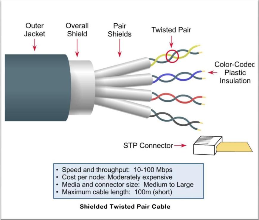
make sure that shields are connected to ground on one side of the cable
The DIN and DOUT Modules (digital in, digital out) has to be connected via Connector Socket J1 to the J8/J9 Sockt on the Core Module
J1 has 5 Contacts:
Put following cables in a pair:
VS, VD
SI
SC, RC
To get more Amperes over the cable make it like this:
VS
VD
SI
SC,RC
I dont know is it clever to put SC and RC in a own shield (pair?):
VS, VD
SI
SC
RC
tips... well read that: Midibox NG
for programming: I did not have to do with the Midibox NG... i took a MIOS32 skeleton and programmed my own concept. and it took a while to understand different things, and many things i dont understand up to now (like OSC and Ethernet)
best you use Midibox NG... they have thougt about how a Midicontroller should work.
when you want to use your concept of only core, and want to add more modules after time or on a running system, you have to add an "OFFSET to your shiftregister pin-outs) ....for example:
activate a LED on a new connected module:
LEDs are connected to Shiftregisters mainly "HC595" this registers have 8 PINs, you want to activate LED0 now, LED0 is connected to Shiftregister pin 0,
All Shiftregisters are in an chain >>> all registers are connected serial one after a nother...if you connect your EXTRA/Modular Midibox to your CORE/MAIN-Midibox - then the chain starts on the core modules, and goes thru all DOUT-Registers in the MAIN-Midibox, until it goes to a connector where you plug your EXTRA-Midibox... well lets say there are 4 Shiftregister in the Main Midibox, the EXTRA-Midibox now starts with the 5th Shiftregisters...
a LED gets software side activated in a way like this (pin, pin_value), so the first pin of your EXTRA-Midibox is: 32 (the pins start by 0, and 4 Registers * 8 Pins = 32 32+0 =32)
so the point is, you have to program a offset to this >>> pin+Offset=real pin >>> the offset could be set by a "Connector switch", a Switch which is Connected to a DIN-PIN, if this DIN-Pin is acticated the Software set a PIN-Offset .... like an DEVICE ID
that are my thougts...
a LED on a specific pin (maybe pin 0) on a shiftregister (a shiftregister has 8 pin
-
checked the datasheet... i tryed 1K Resistors to 15V on the output but with that i got in "low Mode" 1,5V.... high 15V.... but i need 0V @low?
a little bit info pleas- thankz
-
no i would go for twisted pair - shieldet in pairs, or better individually.
daisy chain... yes possible and necessery! all the used shiftregisters has to be connected one after a nother --- and if change the connecting you have to change your Coder!!!! (pin)
it depends on your code - (memory on ic) and on the hardware:
MIOS32 based applications typically allow to cascade up to 8 modules (=32 DIN SRs), makes up to 256 digital inputs
256 buttons or 128encoders.... the same for DOUts
but 16Led rings needs 24 dout pins http://www.ucapps.de/mbhp/mbhp_dout_8x16leds.pdf
i dont made ledrings up to now...so someone other can help!
MIOS32 based applications typically allow to cascade up to 8 modules (=32 DOUT SRs), makes up to 256 digital outputs
-
With one Brain hmm i see:
1. connect the boxes via 5pole shieldet cables (used for Shiftregister and Current) > CAT-Cable, and really keep them short!
or
2. Use LINE-Driver - Boards to expand the cable length http://ucapps.de/mbhp_line_driver.html -
a uln2803 for S-Trig... yes that makes the job

any idea for a transistor array for a V-Trig 15V? for my other organ?
@the moment i use BC337...by the way the Caps make the Piano-Trggers, while the standart output of the BC337 make the Hold-Organ-Trigger

-
the whole midibox hardware platform is modular.... they are all seperat modules that can be chained togehter with standart crimpable ribbon cables.
if you speak of modular you might mean the Case - the housing - the 19" Rack or so > i suggest a system that has a rail for free movable screw nuts, so you can replace frontpanel and backpanel parts when you update the system.... the wireing internal i would make with ribbon cables instead of "power rails" ---- e.g.:
http://www.schneidersladen.de/de/tiptop-audio-z-ears.html
http://www.schneidersladen.de/de/sb-rail-1m-ohne-kante.html
http://www.schneidersladen.de/de/sb-rail-19-mit-kante.html
i dont have tried this products... i only say it is a good idea
-
 1
1
-
-
Bei der Bildergallery gibts zwar das miniaturbild (übersicht/thumbnail), aber wennst dann auf eins drauf drückst sehe ich kein Bild.
-
bei mia föan´s ah ;) < Edit bei (neuen?) Posts sieht mas.
-
first thankz for replay...
1. Make the Organ a midi-soundmodule - means: play sounds via Midi
* i dont want to remote the Soundregisters - i will do that orginal on the device
* that means i Remove all "Gate"-Cables and rewire it via Digital-out-shift-registers
* integrate my trigger-melody software, and a midilooper
for 1 - no problem, except the Ground thing > 0V of the Shiftregister is not Ground enough...may it be the impedance i dont know. ;) i played around with potentiometers, and i got a impedance that worked, but with that the "high"-state is not high enough ... maybe the ULM will do the job!
2. Recable the orginal Keyboard with 3xDINX4Modules....
how ever in the meantime i got a "CRUMAR 198 Sustain" and this device needs +15V @ Gate Input.... a BC549 do the job for organ sounds...a extra10uF and 1K resistors gates the Fade-out sounds (Piano sounds)
the crumar sounds better and it costs me nothing except petrol...
but its good that you write about the ULM.
BLM 16x16+X PCB and case order [CLOSED/waitlist]
in Bulk Orders
Posted
ja ja jaaaaa!