

Zam
-
Posts
625 -
Joined
-
Last visited
-
Days Won
26
Content Type
Profiles
Forums
Blogs
Gallery
Posts posted by Zam
-
-
Well done! :smile:
TKS !!!
without your system it will never happen
Which MIDI events are you using to send & receive the value?For more than 7bit you need either NRPNs, Pitchbend or SysEx
Best Regards, Thorsten.
I use pitchbend of course
the AINSER respond to the bit resolution up to 8 bit but not more
if I set resolution=4 i got 16 PB value in the 16384 range, steeped by 1024, this is OK
If I set resolution =8, the step is 64 which mean 256 value in the16k PB range, this is OK
But if i set resolution= 9, 10, 11 or 12 the step 64 is the same as before with 256 value (8bit) !!! this is NOT ok
Any idea ?
Best
Zam
-
Teaser !!!
-
I'm close !!!
Until now it's a success! hard work but a success :rolleyes:
I'm on the soft side right now and there is something in don't understand about AINSER64
I check different bit resolution, but when monitoring the value I can't go better than 8bits ??? if I go less the value folow the bit resolution !!!
I would like to go up to 10 bit (1024 fader position), which is the MCU resolution.
Any ideas ?
Zam
-
Ok! tks for the clarification.
Hop we can have this one day :)
Best
JS
-
A 14bit map would allocate 32k RAM.
For STM32F1 and LPC17 it wouldn't be possible to provide such a feature, because memory is already completely used by the application.
For STM32F4 there would be a possibility, but it contradicts with other planned features, such as the .NGR bytecode interpreter.
And I got a request to provide individual delay parameters for each key of a keyboard which will consume some memory as well.
Therefore it's very unlikely that I will provide a map with such a high resolution - It's probably better to work on a dedicated application for this usecase.
Best Regards, Thorsten.
Ok i understand that.
Is 10 bit possible like the MF_NG with pic18 ?
But maybe I'm wrong? Is what you call "map" here the same as what we call "table" in mbhp_mf_ng_v1_005 ?
I request this same function but for mios32 and AIN-AOUT
Best
Zam
-
Hi,
it's currently not possible to map a AOUT value from a customized map with the required resolution - I added this to the wish list.
Best Regards, Thorsten.
It will be great !!!
Same principle as the one you made for MF_NG
Do you think it's possible to go up to 14bit map ?
I hope to use this kind of feature in my analog PI motor driver proto using AIN and AOUT
But in a more global view I think it will be a big step for lot of application, from exotic syth to modern analog desk with VCA automation.
Best
Zam
-
I'm in standby again on this, lot of work at the studio.
I'm also waiting to have a decent basket to order some component, I blow so many transistor in the proto :rolleyes:
Hope I can check everything left soon, and make the first 8ch batch (before summer...) then I plane around 6 month of daily use to be sure the system is strong enough.
-
Hey
some update
The analog PI driver work !!!
I have little hard time, with some error, and burning part, but i'm close to have a perfectly tuned motor driver and safe design
IT'S F....ING SILENT at acoustic side I mean, I don't plug it in the desk so I can't tell for the crosstalk at the audio analog side
I will add pic soon :)
Zam
PS: I spot an error in the AINSER64 board (make me fool for on day searching my pb...) at J3, RC1 and RC2 is inverted...
I don't know if it's already reported but It make sense to put some info/warning line at the AINSER64 MBHP description page !!!
-
Hello
I just have a look at .ngr , your right, maybe it's the solution
I just try to be little more familiar with .ngc before
Best
Zam
-
Hey Thorsten
I think I miss a clear explanation :rolleyes:
the MCU design don't have channel "read" and "write" button/led for the automation mode, but only "function" button (right hand) you have to press, then select the channel(s) you want to put in read or write automation mode with each channels "select" button.
My design use dedicated button/led for read/write automation for each channel.
For the moment the "trick" i find is to send a first note activating the "function" (D5 for "read" automation) then send the respective channel "select" note with the same button. It work in some way but my "select" led keep lighting.
The DAW only return the "select" note (I think that's why I can't shut this led off...) also a sysex (the label "read" to print to the channel HUI/MCU LCD)
I'm wondering if I can us this message as a "triger" to light up my "read" led when my daw have the "read" light on
all this is the same for "Write" automation, plus if I hit "write" i need the "read" to be activated (if not before) and if I suspend the read i need the write to be deactivated (if not before)
Hope I'm clear !!! I will study more the ngc user manual, i'm sure there is a nice solution
Zam .... ho! ...happy new year
 !!!
!!! -
AOUT arrives today :) i will test the motor driver soon !!!
My analog touch sensor work fine (on the bench)
I have some software question, is it possible to use a specific sysex message to light up a diode, (and another to shut down the same diode)
I try with event receiver and forward command but without succes.
Zam
-
It should work, latency shouldn't be an issue - but I never tested this by myself, and I can't exactly say how many MBHP_DRIVER modules can be used in a chain.
But with only two drivers in the chain it should work.
Best Regards, Thorsten.
Tks for info TK
I will try! just need to fix/test other part of my build before :)
best
Zam
-
In theory I think it should, although you may run into latency problems if you cascade too many chains. Are you planning to use two different cases? Can you not just run two Cores? Also AOUT is limited to 8 channels for most applications at the moment.
Hello
What amount of latency ? if it's in the ms range it's not a problem for me.
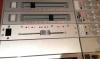
My built is an automated fader system for a 40 years old analog modular desk, I have some room issue in the frame, core and PSU have to be outside (maybe in a 19' rack few meter away), also interconnection/link between subframe (8 modules, channel/fader) need long wire due to mechanical restriction.
It's not really different cases but in fact I have to think like it was :happy:
Multi core is an available option
I read somewhere in the forum that someone run two chained AOUT_NG with succes
This line transmitter deserve a try in my build for sure...
Zam
-
Hey
Interested in this for my build, just have some questions :)
is it possible to chain multiple line transmitter like this ?
CORE<-->line<-->DIN/DOUT/AIN/AOUT<-->line<-->DIN/DOUT/AIN/AOUT
Zam
-
Some update
Today I receive the last components order
I've got 99% of the parts needed, except AOUT_NG... i got MF_NG pcb in place from Tim :sad:
Zam
-
Same as Kristal, isopropyl alcohol is the way to go.
Once I buy "special" flux cleaner, just melt the pcb varnish :angry:
best
Zam
-
Looks like an interesting project! I would be great, to use Motorfaders directly with the Core without having an extra microcontroller running.
Please keep us up2date.
Hello Fantom
My project is not an easier way than MF_NG with the PIC18
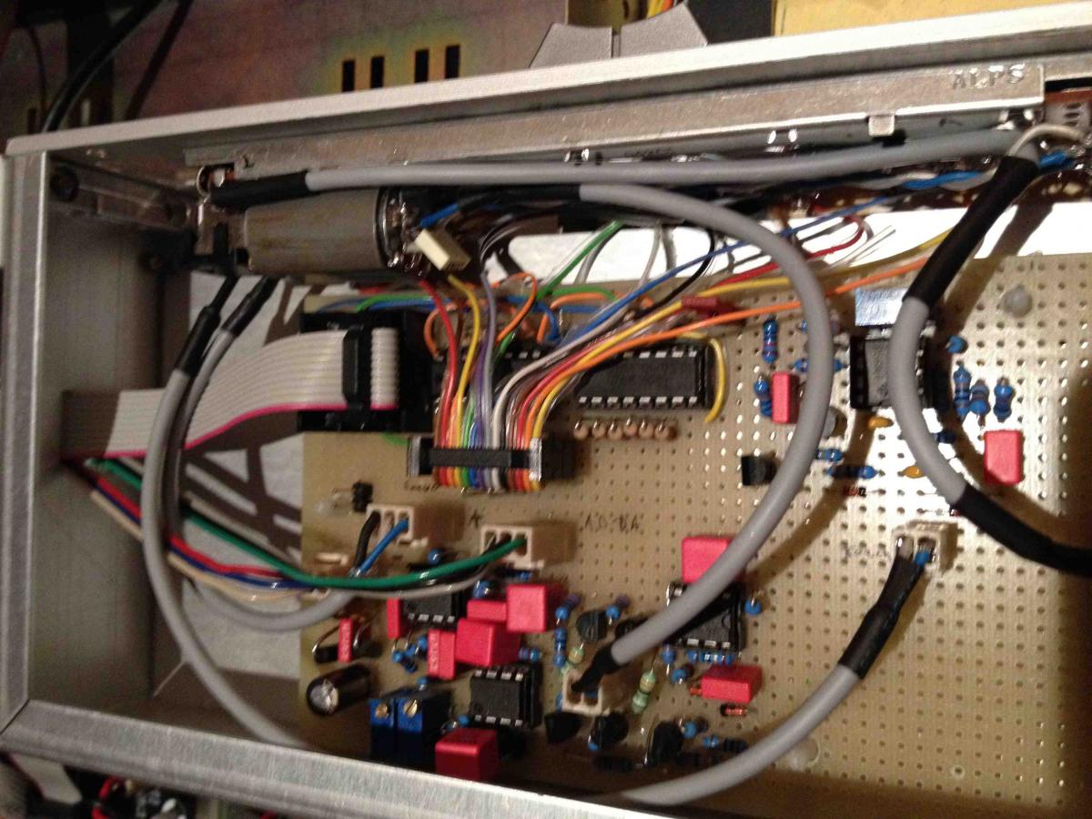
In fact there is more part involved, DA converter driving an analog PI controller for the motor (6 opamp 5 transistor).
Then AD converter to read the servo track position, this signal is buffered (analog side) and splited, AD input and PI comparator
MF_NG is a great system for digital controller only, but I need better noise floor for my analog console, digital/PWM noise leak badly to the audio side.
best
Zam
-
Hi Zam
Well the overall current will depend on the connected parts and modules like LEDs on DOUTs... I can measure the current of a single STM32F4DISCO if you need to know it exactly.
Best regards
Novski
hey
No need now to have exact current. If no table is available, I will do measurement when everything is hooked together.
I plan to order some 3 or 5A psu for the proto, way enough for one fader I think
then I will calculate for a complete system.
I plan to use:
one Dout and one Din, one opamp for touch, 6 button, 6 led, one relay. All this for one fader (proto) but if it's ok i go for 16fader...
One Ain (64 is enough for 16 ch !)
One Aout for 8 fader, two in total.
Best
JS
question for TK :rolleyes:
I don't remember if I ask before, is it easy for you to translate the MF table (to match fader curve) for Aout ?
Best
JS
-
Hello Novski :)
Tks for the power supply precision, now I understand why I never find the 3.3v Input :)
So I just need the 5v for all logic board, excelent !
By the way is there some info about current needed for each MBHP modules? Maybe i miss this too in my wiki search...
Now I think I'm ok with pin assignment for any 10pin J connector.
Best
JS
PS: STM32F4 is also available at RS http://fr.rs-online.com/web/p/products/7458434/
-
Hello
I decide to start a new topic around my fader automation.
As i don't plan to use MF_NG anymore it make sense to not saturate the dedicate topic.
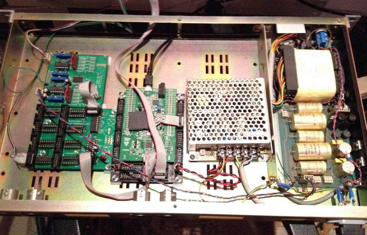
The "rev2" prototype is based around STM32 core
AIN for fader servo track
AOUT to drive my analog PI driver
D I/O for led, relay, button, touch
I design some Din/Dout board based on the matrix but with only 8in and 8out and with integrated touch detection circuit
By this I keep the whole system modular like my mixing desk, each fader will have a dedicated PCB.
80% of the parts and board are on the basket or waiting delivery
I hope running the first test before the end of the year :smile:
--------
Now the questions !
I start to read a little about the STM32 and MIOS32
Last revision include "toggle" mod, "on/off" capabilities for the AIN, acting like a DIN right ?
I'm wondering if it's also possible with AOUT ?
I'm already thinking of v3 proto, with "only" 1x 8AD chip and 1x 8DA chip per fader module, where I can manage ALL led, relay, button, analogPI and motor
Ending with a single "bus board" or "bus ribbon" to the core in a serial mode, (or multiplexer?)
second question is about STM32 supplly
I plane to use external 3.3v, 5v, and +/-15v (for AOUT and my motor driver)
I'm fine with the STM32 J2 description for 5v supply, but i don't understand where I plug 3.3v ?
and last... i can't find any specification for all J connector regarding pin n° and function, the GND usually use pin 1 and 2 or 9 and 10?
Best
Zam
-
 1
1
-
-
Hey all !!!
I'm back to this :)
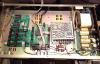
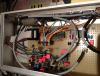
I just ordered pcb from smashTV, in fact a 32 core, AIN, AOU, and DIO
now have to order the BOM for all this, and finish the analog PI pcb under eagle,
Phase II "Studer Motion" on the way :)
Zam
-
Hi Zam
Can you explain me more bout the advantage of this?
I wold like to help you improve your Faders if i can learn something and maybe use it for my Fadercore afterwards..
br
novski
Hello Novski
i'm sorry to not be so active since few weeks, i announced analog PID proto for September, but I have lot of work at the studio, so it's delayed a little.
The advantage of analog driver (if it's the question), is a real variable DC signal. I hope both mechanical and electrical noise will be lowered.
After all test performed this summer I become convinced that analog audio signal and PWM/SH pulse are not friendly, I can't let this project with compromise. My "hi end" desk deserve the best.
Regards
Zam
-
hey Thorsten
you can find the schematic here ftp://ftp.studer.ch/Public/Products/Mixing_Analog/990/Manuals/990_Serv.pdf page 115
Ufader (P9-7) come from the fader, servo track 0-5V (look at page 89, signal is also send to some Ain).
Usoll (P9-1) come from the processor board, IntelMCU out, analog mux/demux and flipflop is folowing (starting page 141), don't know the signal but i think it's DAC 0-5V.
That's here i'm thinking to plug some AOUT with "simple" PitchBend to CV (log with the new table tool).
We just need one output, this is the the target position from 0-5v, the motor direction is given by the sum from this voltage value and Ufader voltage. With 2.5V offset I guess.
The "stop motor" is also at analog side troughs Q5, don't know how to implement this right now I have to think about.
You have the sensor detection circuit at the bottom of the shematic IC3 IC4 Q6 Q7, not sure how it work, but maybe we can use TOUCH (P9-6) going to some AIN or SR so computer and DAW know that something is touched, and route this trough another AOUT going to ENABLE (P9-2).
There is no need for script that stop the PWM or (AOUT/Usoll) at this point, but send some CV to active the gate, and ground the driver input.
Voilà !
I take time (and friend help me!) to understand the schematic, don't be fooled !!! it's not an H bridge (my first visual impression), the 4 transistor are just current helper for IC1-1 and IC2-1 output.
Best
Zam
PS: I'm off link for the next 3 days
-
Ok!!!
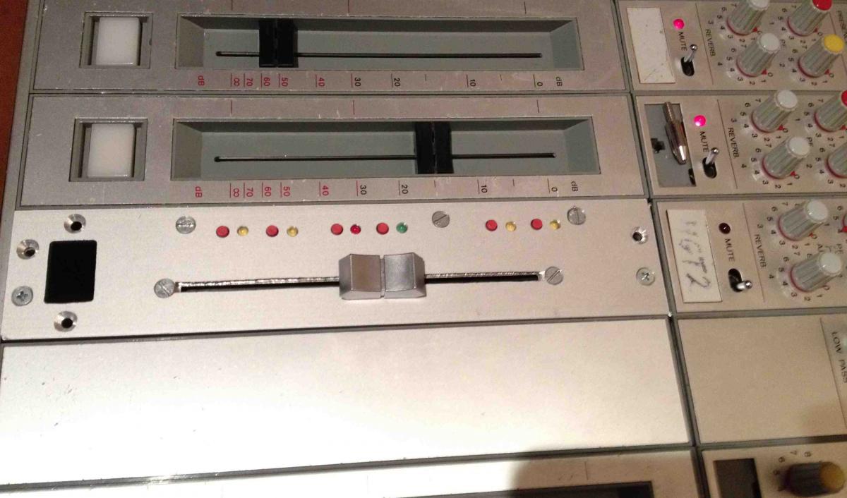
I made a 42 point table !!!, 1dB step from 0 (top) to -30 and 5dB from 30 to cut (bottom). the 0 to 30 dB is about 2/3 of the fader length.
I start with a 10-12 point, 5dB step table, but the 0 to 20dB is critical and realize that the audio taper from my fader is strange in this area, for example the 5 to 10 dB distance is smaller than the 10 to 15dB.
5dB table is accurate at the 5dB step spot but not between, so I decide "super accurate table"
Plus I have two fader so i measure both and made an average table
I have some listening test with stereo track send to both fader, channel full paned L/R, but unmatched level is made pre fader (test for 5, 10 and 15 dB L/R differential)
Then I compensate with fader, link them (group fader in DAW), and move one, the second fader follow the the touched one with accuracy and keep the relative gain with success.
The result is a solid L/R balance without excessive floating center. I think the audio log taper tolerance is the most important factor in this effect.
I don't measure this, but it sound excellent to me, let say not more than +/- 3 ° in my 60° equi triangle monitor installation. Of course it's not so accurate at the bottom of the fader, but I don't care, and I'm not sure a more accurate table will resolve this
Anyway stereo tracking is WAY better compared to my actual stereo fader loaded in the desk.
The matching between DAW fader value and real analogue attenuation is the other aspect of this new table tool, and it work fine
I still have 4dB offset from reading value because my fader DAW is +6 max, but I don't care.
I think "relative" (as dB are) and if I reduce 7dB in the DAW my audio fader move down at the right position to reduce 7dB too
On side effect I think I can't solve, it's the DAW interpolation value when you are in the "positive" side of the fader (0 to +6)
when you are in this area with one fader the other (linked) folow closer and closer to reach the +6 at the same time, killing the relative gain.
For me this function is a FULL success, exactly what I'm looking for, Thorsten you are a MASTER.
Maybe at the moment i'm the only one that have some interest in this but i'm sure all of you will find this useful for some function, like matching a specific dB scale label in your front panel even if it's only a DAW remote, or have some custom curve response under the finger, super accurate in some area...
Tks a lot :thumbsup:
I have lot of work in the next few week, but i'm still aroud. In september i will prototype an analog PI controller from latest 90' analog automated studer desk.
No PWM, no H bridge, no motor noise... smoooooooth DC
I have to think how to substitute the MF board with the AOUT and his DAC, but keep your wonderful soft side
Is that easy to "just" remove the PID controller in the MF soft and assign output not to the PIC PWM but AOUT ?
best
Zam
Upcoming MBHP_MF_NG module
in MIDIbox HUIs
Posted
hello
I find (in my particular situation) that motor EMI is a problem, especially when running PWM and H-bridge system close to hi gain analog audio, even with fully separate supply rail and ground, layout is important, also mechanical integration and room between both elecronic.
The "problem" is that there is one place you can do noting, it's the pot or fader himself, where audio track, servo track and motor share one mechanical system you can't change
After 6 month building a protoype, I can tell the ALPS fader don't do the job in this situation. I think it's mostly due to the motor position.
Rotary motor pot is different, I can't say, you have to try.
In other hand, an automated fuzz pedal with motor brush noise in an unique FX :smile:
Zam