

Zam
-
Posts
625 -
Joined
-
Last visited
-
Days Won
26
Content Type
Profiles
Forums
Blogs
Gallery
Posts posted by Zam
-
-
Hi mongrol
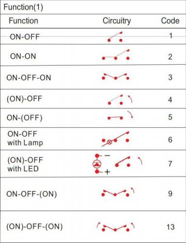
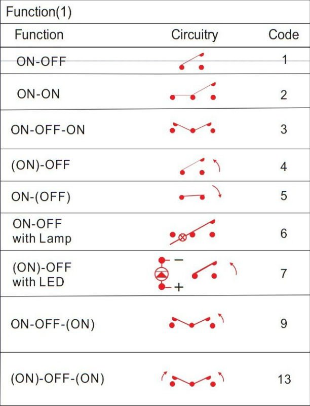
(on) mean momentary on
with on-(on) spdt, you have one position with on condition and one position with momentary (on), which come back to the first on position if you release the button :)
Best
Zam
-
 1
1
-
-
This project is absolutely wonderful

-
Hi
Just an idea, not a real need (but it can be fun, and i will use it for sure)
something like a led_mode=blink for .NGC with associate parameter blink:on:100:off:300 for time in ms for each led state?
or defined time with 2 value map
or just 3 "blink" predefined mod, blink_slow, blink_mid, blink_fast
Anyway, the idea is to have a blinking led function when led is on, because a NGR script (set led and delay) is stopped a soon as another section is called
Best
Zam
-
Hi all
Is a week without reply a yes or a no ?
I'm sorry to come back with this but I need to know if you guys are interested in this and if can extend my project to other ppl.
I have some request for It, ppls are waiting

Best
Zam
-
update
It's definitely liked to the optocoupler when I touch my fader, which have no link at all at ngc or ngr side.
If I remove the optocoupler from .NGC (event_led) the problem disappear.
Still don't understand how the manner of resetting the system have influence on this.
Anyway i believe it's part of my hw implementation, you won't be able to reproduce it I think ?
Maybe how the Din/out chain is scanned/setted up at reset, if I put the bug condition (led on, opto on, touch etc) at several fader, only most lower in the srio chain have the bug
Just forget it, I have no problem to type "reset" manually when I update my NGC.
Best
Zam
-
Ok
here is first test.
the flashing led don't react the same with SRIO num_sr=8 or without (less flash)
also
If I save an .NGC at file browser tool (with reset_hw command) the system return (at main window midi in monitor) a dozen of note off event (which some of them are not used by any event in my NGC)
If I reset with direct "reset" command at mios studio main window, the system only return two line F0 00 00 7E 32 00 21 F7 and FC
it seem the two way to reset don't do the same
Listen TK, if you have absolutely no idea about this it's not a problem, don't waste your time now, it's also possible it come from hw side (it's at some point dependant to the fader touch and optocouper, maybe AOP oscillation)
Best
Zam
-
Hi TK
it seem the issue arrive since I build more and more complex NGC/NGR, as I don't remember having it at the beginning when only few Din/Dout where assigned with event_
So I don't know if "minimal" will do the trick, I attach the actual NGC/NGR
In other hand I don't perform more test on this (as it's easy to solve with a mios studio command or core reset button)
I will try to see what config start to be a problem, by removing group of event
Best
Zam
-
Hi all
For info
I just check STM32F4disco at one of my regular component supplier, and there is a new one coming soon.
So I check at manufacturer and the board is now NRND, replaced by something looking absolutely the same but with STM32F407VG in place of STM32F407VE.
http://www.st.com/web/catalog/tools/FM116/SC959/SS1532/PF252419
I have no knowledge for understanding/comparison about change.
Just to let you know there is certainly a need to check what's going on, and be sure MIOS/MBHP will run fine with new STM32F4 board
Best
Zam
-
Hi TK
Yes it's the first command in my NGC
So this command should reset when loading an NGC not only at start-up/power-on the system ?
Best
Zam
-
Hi
I have a question regarding core update/reset
I notice that if I update an NGC file with mios studio, I have wink leds when pushing some buttons, this leds and buttons are not linked in any way at soft side.
But if I reset (via mios command or at core32 button) everything go fine after. It's like there is some phantom function after an update, which request a reset to definitely put in hell
I believe it's happening since I have a more and more complex .NGC/.NGR files, but I can't tell when I first observe this.
Is that a bug, is that normal ? To me it's not a problem, I just ask to understand

Best
Zam
-
Hi all
As maybe some of you guys here already see, my moving fader system is close to the development end
It use MIOS and some MBHP part (core 32 and line tx/rx)
In few point, it's not eligible for sale request
-it's not cheap at all
-I don't plan to share layout in a close time range.
I start to take temperature and interest at groupDIY forum, because it's a place were this kind of system can have echo too
I don't plan to sell, ready to go system, except if someone ask me but I don't believe it will happen.
The idea is more selling PCB or partial kit, nothing is decided yet.
There is interest for sure, at the end maybe 5 or 10 pple will effectively invest in this for a first run, it will not be a mass production at all...
So let me know what you think around here, because interest at GDIY is growing up, and If there is now way to do It I have to quickly stop all hope the guys have, to avoid disappointment.
Best
Zam
-
Hi Eric
I start a new thread at GDY
I don't see this chips when I look to smooth PWM 1 years ago.
Yes maybe it would simplifies the design, with less component. Still need to have "power" output to drive a 10 or 12 V motor at 200 to 500mA ! buffer and push-pull ?
Also the PID have to be at soft side then, I'm not a programming guy (that's why I'm here
).
Finally I don't find MSOP pakage so diy friendly with 0.5mm footprint.
It could be an interesting other route, if someone like to try it with actual MF_NG.
But what I see then, if you already have PID at soft side, just use a DA with powered output...no PWM
Best
Zam
-
Hi
It all work, it's just amazing, the new map are so great.
TK I really like to thank you, this was the final touch to the moving fader.
I have two fader with different log scale, both different to DAW fader scale, now everything is moving relatively (dB) the same.
Fader grouping keep gain staging at analogue side.
I now have to check how it change the steep definition, which is non longer linear.
Side note, can I say that -ainser pinrange- is redundant with map?
This new map just open a new world, I have to try to drive audio vca laying around with AOUT_NG !
What about a digitally controlled compressor/gate !!
Also I sea the abilities to use CV note with non tempered or custom scale !!!
Best
Zam
-
Hi TK
I will check this evening and report back
Many thanks
Zam
-
Ok the button/led pattern problem is spotted, it is linked with the map in 1.034
I use a map and 2 button toggle mode to swap 4 interactive state (2led/2button), calling meta script, like an "complex" radio function
automation Off/read/write-touch/write-latch
map is a simple two value -MAP100 1 2-
I just realise the whole function pattern where inverted so I try -MAP100 2 1- and it work like before !!!
here is NGC for one button/led pattern (have 8 like this in total)
QuoteMAP100 1 2
##########
#read
EVENT_BUTTON id=5 type=Meta range=map100 meta=RunSection:1 button_mode=Toggle value=2
EVENT_LED id=3##########
#write
EVENT_BUTTON id=6 type=Meta range=map100 meta=RunSection:2 button_mode=Toggle value=2
EVENT_LED id=6and corresponding NGR part
Quote########################################################
#Fader 1
#Readif ^section == 1
if BUTTON:5 == 1
change LED:3 127
change LED:6 0
send NoteOn USB1 1 0x4a 127
send NoteOn USB1 1 0x18 127
send NoteOn USB1 1 0x18 0
send NoteOn USB1 1 0x4a 0
change BUTTON:6 2
endifif BUTTON:5 == 2
change LED:3 0
change LED:6 0
send NoteOn USB1 1 0x4a 127
send NoteOn USB1 1 0x18 127
send NoteOn USB1 1 0x18 0
send NoteOn USB1 1 0x4a 0
change BUTTON:6 2
endifexit
endif############################
#Writeif ^section == 2
if BUTTON:6 == 1
change LED:6 127
change LED:3 127
send NoteOn USB1 1 0x4b 127
send NoteOn USB1 1 0x18 127
send NoteOn USB1 1 0x18 0
send NoteOn USB1 1 0x4b 0
change BUTTON:5 2
endifif BUTTON:6 == 2
change LED:6 127
change LED:3 0
send NoteOn USB1 1 0x4e 127
send NoteOn USB1 1 0x18 127
send NoteOn USB1 1 0x18 0
send NoteOn USB1 1 0x4e 0
change BUTTON:5 2
endifexit
endifBest
Zam
-
################################################################################
AINSER n=1 enabled=1 muxed=0 cs=1 resolution=10bit
AINSER pinrange=1:4:4088MAP122/HWORDI 0:0 160:320 319:570 535:1014 1026:1803 1515:3207 2019:5703 2479:7605 3037:10141 3521:12053 4047:16383
EVENT_AINSER id= 1 hw_id=1 ain_mode=direct type=PitchBend chn= 1 range=map122 value=0 if_equal=button:8:1
################################################################################
AOUT type=AOUT_NG cs=0 num_channels=8MAP123/HWORDI 0:0 320:160 570:319 1014:535 1803:1026 3207:1515 5703:2019 7605:2479 10141:3037 12053:3521 16383:4047
EVENT_CV id=1 type=PitchBend chn=1 range=map123 value=0
---------------------------------------------
Here it is, map 122 and 123 are inverted (i'm not sure about this?)
My map is fast done, 5dB then 10dB step according to fader real attenuation
The point is to have DAW and real fader attenuation matching, the sended data to DAW work fine.
This is for one fader, MCU protocole
Button 8 is just the touch sensor to send data only when touched
Best
Zam
-
Just now, TK. said:
CV: if you need special changes for your usecase, please let me know
Best Regards, Thorsten.
Yes, my system is bidirectional I "need" the map to also work for Aout, in fact I will use the exact same PB map for in and out
Best
Zam
-
first report Ain seems to work fine
have strange things with my button led NGR patter, but I don't look deep and it's another topic
Just don't see Aout/CV in the supported hw, I will try now
 , maybe with sender/receiver?
Best
Zam
-
Hi TK
I'm just lost my voice!!! 16 bit map

I report ASAP, I believe I will work late on this tonight.
Man...thank you
Zam
-
Yes I know you can help :)
Let see how groupDIY community react, i just ask for "interest" to see the potential of this project. there is so many things to coordinate if a release is made. Including bridge with community here at midibox
best
Zam
-
hey
No, I can't add another 5V rail just for servo, AD and DA chips reference will not be the same, or won't "move" the same.
For now I think something like a 5V "star" layout will be the best compromise, But the I/O board is just busy as hell, I design a 2 side PCB with ground plane for 64D I/O and 8 A I/O. and the ground plane is clean as hell !!! so just imagine the bottom side
yes that's my default... i'm a perfectionist...
your link is instructive... I just miss the 30% one years ago...
best
Zam
-
Hi Eric
I'm little stuck to fund a full 8 fader pack right now...(I have a desk for sell if interested
 )
)
I have two TKD fader loaded and it work great, I still have one issue, I reduce the problem a lot, I have to decide if I can keep it this way
I made few little mistake in the layout that require a rev 2 board for motor driver and I/O board. Main error was a buffer amp wired as inverter in place of non inverting, and some footprint error like wima filter capacitor with 2.5 in place of 5mm. I just cut trace and rework PCB for now, anyway, it need correction at KiCad schem and layout for a realease
The real issue I just talk about, is voltage drop at the 5v rail with all led ON, I also use it for servo without local regulation.
It just corrupt the AD side stability of the system, by changing the reference voltage, introducing comparator error and fader move.
Initial layout put this error in the mm range, completely unacceptable.
I was able to reduce this in non perceptible range by // 5Vtrace with 0.25mm2 wire and connect the SMPS sens at I/O board (prevously 3m away at the 19" rack with the core).
Now I'm in the 10mV drop range which still enough to introduce jitter at 12Bit AD and of course error at analogue comparator.
As I say it's non perceptible, at worst 2 step<=>0.2mm (7 led ON), and this "jitter" will always be the same.
I mean for example in read mode the green LED will always light on, introducing exactly the same error for each pass, without relative difference. The worst is with mute function which light a red LED and an optocoupler, but If I mute I don't care the fader move 1/10mm
So here it is:
Do I keep it like this, not so smart design, with my subjective knowledge saying "it's not the best possible", when objective observation show it's just out of human perception.
Or do I push a little more further and add local regulation, which will implies deeper modification.
I still have 5V layout modification to made, not easy to change the "basic" when all complexity around is done, maybe I have to go for 4layer pcb! I don't see to just add 5V wire jumpers a very professional design.
There is few option and I have to make the right choices to avoid V3 to soon...
Last important thing for the system is the the data mapping at soft side, also OSC, but that's another topic.
I have few call at groupDIY, I wish I can release this.
For info, I/O board is 250x85mm, not more than 30cm cable/ribbon from the fader/motor board.
Motor board is 34x120mm as close as possible to the fader,
and remote is 16x150mm as close as possible to the front panel :)
Best
Zam
-
1
-
-
Hi
Maybe I'm wrong but is't the DAW automation internally sinc'ed with MTC ? anyway MTC is 120 tick per sec at best (30f/s with quarter)
So using DAW is in a way the same as embedded MTC, just without all this code to write
Full range respond is 100ms for my system so the 10ms lag is negligible to me, and no need to be better. I don't plan tu use the fader as fast compressor :)
Regarding precision, I feel 10bit is way enough, it's 0.1mm steps !!!
The re-recording test show me that two pass reading the same automation with the same audio result in a phase cancellation that i'm not able to cancel better with +/-0.01 dB trim, at static step of course. I was myself very impressed whit this result (pcb version, protoboard was not as good)
For smooth and detail you have to see the fader with 30min ramp, you just don't believe it's moving, you come 5 minutes after and the fader had moved 1cm
For me the PID has nothing to do with the automation data, comparator is at analogue side, whatever data you print/sendback. What kind of error you have in mind? I'm not sure to understand what you mean.
Best
zam
-
Hi TK
I'm glad we find the problem. But I'm absolutely not in the hurry for this right now, so if I'm the only one having problem with this you can delay as you like.
I need to learn more about OSC anyway, I still don't get how to handle OSC strings with MBNG and .NGC
Best regards
Zam
89MotioN using MIOS
in Sale Requests
Posted
Hello Thorsten
That's great, thank you
Let's move forward then
Best
Zam