Nintendj
-
Posts
30 -
Joined
-
Last visited
-
Days Won
1
Recent Profile Visitors
986 profile views

Nintendj's Achievements
MIDIbox Newbie (1/4)
1
Reputation
-
Thanks all, for the patches!
-
Yup, audio input is shorted to ground.
-
No matter what I try, I can't get rid of hum on the audio. There's alot of it! The only way it seems to get rid of it is to run a 5V regulator on the output of the 12V regulator. Then I thought the old regulator and parts in the PSU were just done for, so I replaced them all. New regulator, new capacitors, resistors removed. Basically the only thing left original in the PSU is the transformer. No change. Still the same amount of hum. Then I thought it was crosstalk in the cable coming from the PSU, so I shortened it by half and resoldered the plug. No change. Then I measured the original power switch, which I was still using. There was crosstalk/leakage in it, removed it and put jumpers instead. No change. Now I still think it's the cable. There doesn't seem to be anything else left! Running everything off the 12V regulator is probably going to kill it, unless it gets some serious cooling. So now I'm thinking of running the display and LED's from the PSU 5V and the IC's from a 5V reg on the 12V reg output. I'll put a small heatsink on it. Hopefully that'll fix it. School's long gone and I failed the course... Still, I want this synth! This is driving me crazy! :pinch:
-
Another PCB problem.
-
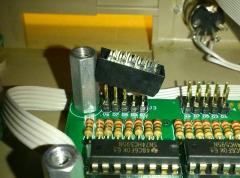
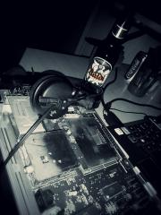
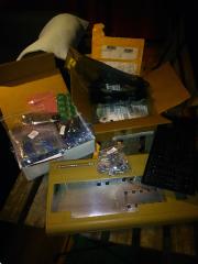
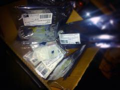
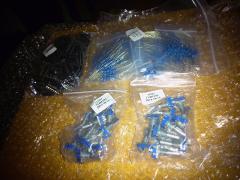
Pictures of my Midibox SID build. http://midibox.org/forums/topic/19104-build-anatomic-instruments-sid-build-thread/
-
-
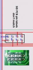
The pin labels on my SmashTV SID PCB don't match the schematics. I was going to ignore it but then I noticed that pin SC is on the PCB and the schematic, but not in the same place. According to the SmashTV PCB, Core pin MD gets connected to SID pin SC while Core pin SC is connected to an unlabeled pin on the SID PCB. Should I ignore the labels on the PCB?
-
I see that now. Thank you. :P
-
From the V1-to-V2 user manual: This is the only mention I've found on how the SID modules are wired to the CORE module. Is this correct for new V2 builds also? Is it SID J2 to CORE J10 pin to pin exact, except for the second SID module, which connects pin SO of J2 to the J14 pin on the CORE module? Is the module to module wiring discussed anywhere else in the user manual?
-
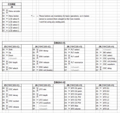
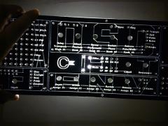
Thanks jjonas. The 'SID select' button in my layout is actually the 'SID L-R' button, because I'm simply building a single core stereo SID. Here's my revised pinout:
-
I guess not... :( That means I've got to compromise, to cut two buttons out so that it fits on two DINX4 modules. I'll cut 'SID select' out and then I'm thinking about cutting 'OSC sync/ring'. Those of you that have used the synth somewhat, how often do you find yourself turning on ring modulation? Also, since the sammichSID has no dedicated buttons, that means that you have access to all settings on the display/menu, right?
-
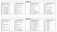
Thanks Imp. To clarify what I'm trying to do, here's my planned DIN pinout table: ...but as seen in the following picture: ...there doesn't seem to be a J5 function for digital input and all digital ins in the DIN tables are assigned to specific shift registers. Can I somehow utilize J5 for digital inputs, without coding the support myself?
-
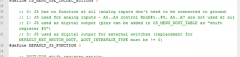
According to the http://www.ucapps.de/mios/j5_din_v1c.zip'>J5_DIN example readme, when J5 on the core module is configured for digital input, it will send midi notes for each button press. That is not how the DINX4/shift register modules work, is it? Also, does that mean that I have to specify the midi channel during compiling and then keep the synth configured to that channel indefinitely? Perhaps I'm misunderstanding this?
-
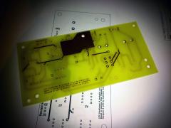
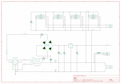
PSU I will be using the original C64 PSU that I got with the computer. I measured it using a multimeter and it seems fine. When I've built the regulator PCB, I will measure it's output with an oscilloscope. The 5V will go pretty much untouched to the Core module/PIC, as it is in the original C64 schematic and the Midibox schematic. The SID will be fed with 12V coming from a regulator. Here is my schematic for the PCB: I will release the complete KiCad project when it's finished.
-
He just updated his Status page. This means I might be able to finish the synth before school's out.
-
It's getting to a month for me also. I'm glad he's showing signs of life. :)