

mongrol
-
Posts
241 -
Joined
-
Last visited
-
Days Won
5
Content Type
Profiles
Forums
Blogs
Gallery
Posts posted by mongrol
-
-
Looks good. My desire would be to shrink the CS considerably (at least by a 3rd) and reduce the amount of buttons as well. However, button reduction would be a massive talkfest as it would require analysis and refactor of workflows which would impact a lot of code. Not being a modular guy I haven't considered Euro but I agree it would have to be a requirement. Rather than clutter the thread I'll go back into my cage and think for a while then write something up in design concepts.
Note: Sparkfun button pads have largers spacing and also come in 2x2 grids. The pcb pad footprint is also available.
-
11 hours ago, latigid on said:
A query, perhaps for v4+: would it be possible to handle track selection (1-16, not in Groups), trigger layers and parameter layers with 3 encoders rather than button/menus? If I was to design a new SEQ CS (just an idea for the moment) the left-hand buttons could be swapped out, reducing the overall PCB height = cheaper.
I'd love to do some design work around a new CS. Is there an archive of previous discussions? I presume a lot of talking was done to arrive at the current layout.
-
3 hours ago, jarvis said:
FWIW - I would not recommend these white on black LCDs from buydisplay.com - the refresh rate is terrible and there is significant bleed from the backlight
*facepalm*
-
Yeah fair enough. I'm having a grumpy day. :) Pulled my old Midirex out to get some jamming done and it kept hanging on me too. Just one of those days where nothing goes right. Although I do like these days in that they put things in perspective in how much "stuff" I have to maintain.
Will get some cheapo buydisplays and see how we go. Least I get 6 weeks piano practise waiting on them arriving. :D
-
One of them broke when I was removing cable. My cables are on angled pin headers to fit my enclosure and the little copper coil thingy close to the pins broke off as it was tight to the IDC socket. Tried to repair and replace it but too small and fiddly for my big ol'beef fingers. The other broke when I was changing the J80 jumper back to J68 and the pad came loose. Again, big ol'beef fingers.
So right now I have a choice. Go with some LCD's which isn't exactly plugnplay as I have backlights to deal with, or go with more Oled's. I've found RS sell Vishay brand for about $30 USD each (cheap or what!) and again, appear to be identical to Raystars.
What I don't get is how I had them working flawlessly before. 1 Raystar and 1 Midas, running off 3.3v with the jumper at the the default J68. 0x02 in bootloader and both displays worked everytime. Now I've replaced the core with a newly flashed one it all stopped giving me joy.
I have another choice. Sell the SEQ parts off and be done with it. :|
-
Hmm, my Winstars also have a jumper set to J68 (the pcb is exact same as the Raystars) but previously I had both working fine (after a lot of kerfuffle). Off to dentist, will change jumper when back.
Buffoon Edit: I don't have Winstars at all. I have one Raystar and one Midas.
UltraBuffon Edit: Now I don't have any oled's. Changing to J80 gave me the same odd chars as Jarvis but I broke one in the process. Then doing more elimination broke the other one. Bums, cheapo LCD's for me from now on. Oled's are too much hassle.
-
@tk. Yep, these Oled's were perfect before I b0rked by discovery board. I'd forgotten about the 0x02 though... so...
- Uploaded boatloader_update app
- Set lcd_type 0x02
- Store
- Reset
- Looked back in my enclosure thread and checked my previous voltage for my oled's (it's clear it's 3.3v on the pic).
Both screens still won't work at the same time. I remember having a helluva time when building this first time around and somehow in my build thread I came up back to 5V and 0x02. However, every photo I look back it it's clearly set to 3.3v.
Time for more oxygen I think.
-
What a timely coincidence. I'm repairing my SEQ atm and have the exact same issue. I have Winstar OLED's which are the same component as the Raystars. Here's the datasheet.
I've replaced a fried MB997C Discovery board with a brand new one labelled MB997D. I haven't changed any jumpers on the core board. OLED's are set to 3.3v. The result is the same if I run over USB or 5v direct power.
One OLED attached shows fine. Two just come up blank or the left one shows a few odd characters. Wasn't there a trim pot contrast adjustment thing at some point in the build or am I thinking of a differenet project?
-
Muha! Language is a beautiful thing.
The new discovery board I received was a MB997D. I was going down the Core page verifying my build when I noticed there was a firmware update to make the new model D run from USB. Downloaded from ST.com, flashed and it works!
TK: On the core page it states the new firmware is untested. This isn't true now. :)
Now to put this bloody orange box back together for the LAST time.
-
So my new DISCO arrived today and it does the same thing. Disconnected everything (OLED, MIDIIO, CS) and left it on the Core board and the same. No response from it. Remove Disco from the Core and it appears correctly in MIOS Studio. It appears a component on my Core board is fried. Time to follow the schematics. :)
-
It's toast. Good job these things are only $30.
-
I've been moving my battlestation back into my Cave this weekend after it was vacated by a "visitor". Unfortunately in my rush I plugged my SEQv4 into a 7.5v supply which I use to power the majority of my kit. Every light came on with no display. After realising my error and going back to the proper 5v supply I have the same result. Every LED on the CS lights up, no display or response otherwise.
Have I fried my Disco board?
-
#7 Final Assembly
Oh dear. Too many reserved posts. This one can get deleted.
-
#6 Finished
Here's the finished result fully assembled with dark grey tinted glass inserted. I don't gig so these just sit in instead of gluing with acrylic glue. I've tweaked the glass template so future cuts may snap in tighter.
OrangieBoomTish!
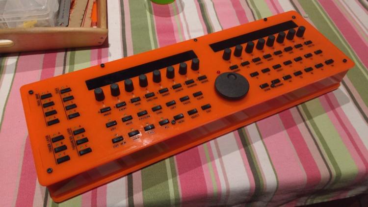
Thanks go to some named person who I've still neglected to credit properly in all my threads for the initial Ponoko panel template. :)
-
#5 Power Socket and Switch
teUSB power for the SEQ is rubbish. It ties up a socket that could be driving a synth (more synths!!!) so Mongbox comes has a back panel option with switch and DC socket holes.
These are fairly standard 6mm DC jack and a 19x13mm rocker switch.
- Make sure you remove the USB power jumper
- Ensure your external power supply is 5v only. STFM04 won't take more.
- Get the polarity round the right way.
- Route the positive through the switch.

-
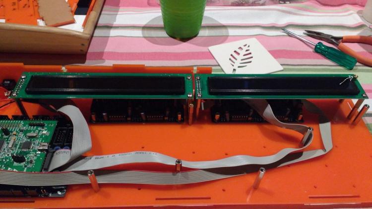
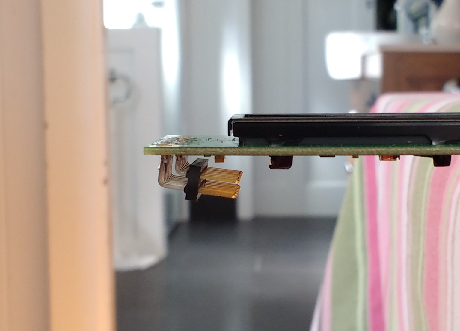
#4 Displays
This is where a custom part comes in. The displays sit on top of 35mm stand offs in order to not having any bolts on the top panel. However, this means the standard vertical IDC connector can't fit between the standoffs. So we need to fit an angled one, and it needs to go the right direction. These are just as common as vertical ones and can be picked up at mouser or any leccy store.
Observe the angle of the pins. They aren't quite right angled but point down a little. The is to allow the IDC female socket connector space to fit between the pins and the PCB which sometimes has little springs or other components.
Tips
- Solder the pins in place with a female socket connector on the pins. This ensures proper clearance from the display PCB
- If desoldering existing vertical pins be GENTLE and SLOW. Oled's especially DO NOT LIKE HEAT. Snip the pin array into little separate pins and desolder carefully.

Here they are mounted. Note the 5mm standoff on the back right corner.
-
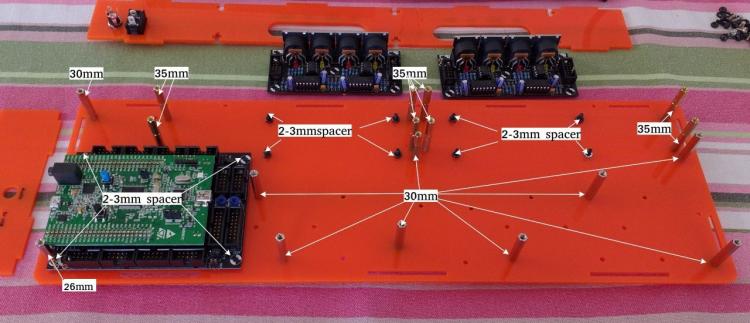
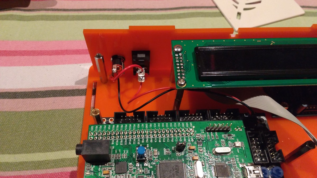
#3 Base Layout and Standoffs
The core sits on the left with the 2 MIDIIO's underneath the displays. The top panel only has holes for the corner standoffs and 2 along the long sides (rear panel are keyhole nut/bolt style). All the other holes can be used to hold the Wilba CS upwards without being exposed on the top panel. I only use the ones in the picture below but there are plenty spare if you like that extra structural stability. You can use a 30mm to CS then 10mm (male downwards) standoff to top panel. This gives good rigidity without needing more holes in the top panel. Recommended if you're a gigger.
Fixings detail
- The Core and MIDIIO's are on 2-3mm spacers. I use m3 nuts.
- All CS standoffs are 30mm with the exception of....
- ...the front left standoff on the core is 26mm (3mm spacer + 2mm core + 1mm washer + 25mm standoff + 2mm CS + 10mm = 42mm)
- From the CS to the top panel you need 10mm standoffs. This gives nice clearance for buttons. You can experiment here.
- The displays sit on 35mm standoffs.
-
The back right display corner needs a 5mm standoff/spacer to the top panel. This is a corner bolt.
Other Notes
- The sides are 43mm high.
- All my standoffs are female both ends with the exception of the 5mm LCD->Panel which is male downwards.
- Plastic spacers can be used instead of hex standoffs but are hella tricky to insert.
-
Ensure everything is tight. You have multiple parts screwed end to end. A middle one could come loose and spin leaving you stuck on the outside.

-
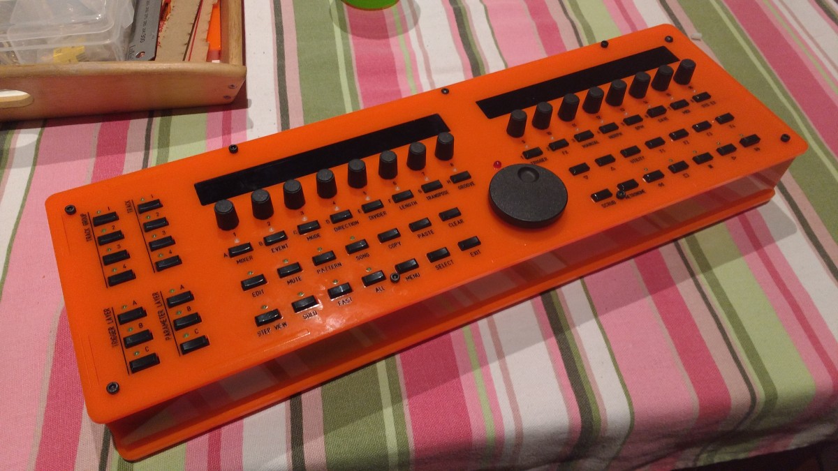
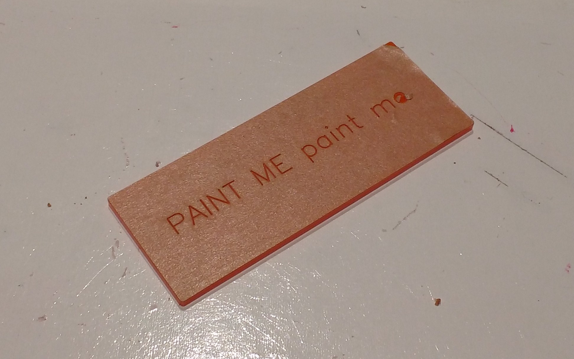
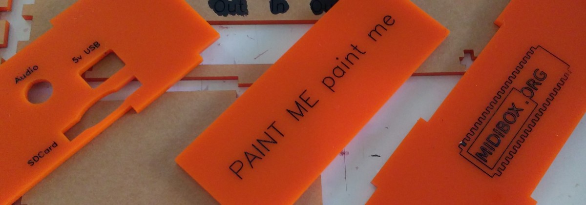
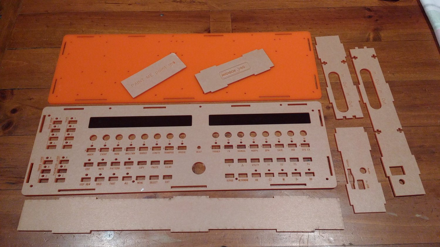
#2 Painting

The template includes a handy "Paintme" piece for you to practise painting the engraved labels. The last time I used hobby enamel paint and it worked great. Paint over the engravinga, wait a minute for it to dry a little then wipe over with a nail polish remover (acetone) on a soft cloth. Generally you need to do this about 3 times to get a good fill.
I've tested painting with both paper on and paper off. The results are almost identical but the process with the paper on is so much faster. Don't be afraid to dollop the paint on. It'll dry in and you'll have a good fill. Peel the paper off and scratch off the little letter loop paper dots with your nail. Borrow someone with nails if you don't have any. Children are good for this.
Afterwards you'll probably find little artifacts where the paint is thin. Paint over these, wait a minute then wipe off the excess with some paper towel and nail polish remover (acetone).

-
COMPLETE
Hi All,
In my build thread I designed and built a Ponoko enclosure and promised to make it public with a proper thread on it. That enclosure had some bugs which prevented me doing so until I'd revised and verified the design. So here it is. Nearly.
This enclosure is designed to reduce the amount of screws exposed on the top panel as much as possible without deviating too far from the original Wilba/Midibox design. To make it fit you will need some extra parts listed below. It comes with an option for rear panel power switch and socket cutouts. Also included is a "Paintme" piece for testing label painting.
Parts Required
- All screws, spacers and standoffs are m3 (3mm thread)
- 10mm screws and nuts. I like black hex socket heads.
- 1x 25mm standoff (f/f)
- 1x 5mm standoff (m/f)
-
Many 10mm standoff/spacers
- If using 10mm spacers beneath top panel you'll need 20mm screws to reach the standoffs under the CS)
- 4x 35mm standoffs
- 2x 10pin angled IDC male connectors
Note: You can make up standoffs from smaller lengths. Buy a kit from ebay around 200 pieces for <$10
SVG's on Github
https://github.com/mongrol/mongbox_enclosure

-
Thanks jjonas, somehow I missed that bit in your guide. Note Save & Take over patterns enters the current pattern set (and saves it) in the pattern mode slots, A1, B1, C1 etc. and it enters it in the same song slot (A1, B1, etc). It's not the same as "Take Over Patterns" which enters it in the currently selected song position. I've just tested the ToP and it's very nearly a Snapshot as it correctly copies the mute states into the selected song slot. The following long would enhance it even more.
Advance song position to next blank position (End position?)
If mixer map has changed from previous create entry with current mixer map
Advance song position
Take over patterns to position.
A default loop x option would be handy which sets the song slot to play X number of times.
Thoughts anyone? I'm trying to make a song workflow that gets a start to end song draft down as fast as possible with minimal interruption to the creative flow. Also hopefully with minimal development effort.
-
I've noticed in the Song mode there's already something existing that's almost Snapshots but not quite. Pressing SELECT in song mode brings up a utility menu with options on the right screen called "Takeover Patterns" and "Save & Takeover Patterns". I can't figure out what takeover patterns does as the manual doesn't elaborate it but "Save & takeover patterns" save's the current mutes, mixer and patterns into one of the bank slots.
It's not quite snapshots though as you only have 16 bank slots and a manually written song sequence could be much longer than that. This function could be tweaked a bit to provide a more fluid workflow. I shall read and think and come back.
-
Cool. I presume this uses the Pro's open firmware API that was released? Did you reuse any MIOS BLM code or have to reimplement from scratch?
(Now how to we scrape the labels off teh round buttons and light them up? :) )
-
Check the data sheets of your caps and knobs to see what size button and pots are needed. Also with knobs they will be Spline, or D-shaped. Then find the pots and buttons you like and check their datasheets to ensure your caps and knobs will fit. With knobs check the depth/height of the stem as well as the diameter.
-
I don't know why the data wheel is involved in this. I'd rather use the data wheel on select step but for some reason I need to have it on select page(?) in order to do ramps beyond 16 steps. Would be nice if it was decoupled entirely from this functionality.


MIDIbox SEQ new frontpanel idea
in MIDIbox SEQ
Posted
Ah yeah that is a bit smaller right enough. Maybe a bit more UI tweaking could rid us of the track buttons(or knobs) AND the datawheel as well chopping another 30mm off it. Of course, the display's still get in the way with that pcb surround. Hmm, I think my ideas warrant more of a major redesign and UI workflow more than current design optimisation. Still, with jelly cube buttons and led's your design would be a very nice modernisation.