

Noise-Generator
-
Posts
193 -
Joined
-
Last visited
-
Days Won
18
Content Type
Profiles
Forums
Blogs
Gallery
Posts posted by Noise-Generator
-
-
Why is it wrong? It just says "Hello World"
-
Indeed.
There is no magic setting up this thing, you just need to follow the instructions here http://www.ucapps.de/midibox_sid_walkthrough.html at
Setup the Core ...
Now you need to up...
-
Maybe it depends on your Midi Interface but if you could have uploaded MIOS 8, it should work.
Took a look at the White and Blacklist http://www.ucapps.de/howto_debug_midi.html (Blacklist Link at ...via Loopback)
-
24LC512 - 512K EPROM 8
Exactly, you need 7 and one 256, because the last bank is for ensembles and only needs 256kb but it's no problem to use a 512, it's just more expensive.
The Voltage Regulators depend on which SIDs you use.
Are you sure you need 2 7809? I'm too lazy to check this but I can't imagine that you need 2.
-
 1
1
-
-
Thank you very much Thorsten,
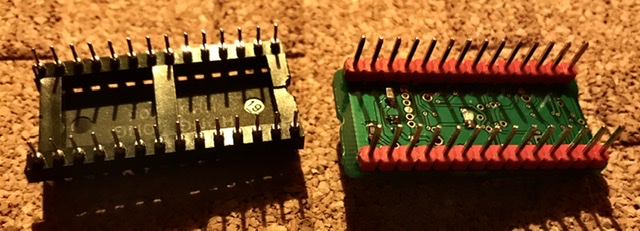
if I wouldn't be lost in Giana Sisters since an hour, I had postet that I found the problem. It's because the SwinSiDs I own do have very fat Pins and they gaped the holes in the IC sockets. I couldn't believe that but putting a SID in an extra socket, full contact and working. I just did that because I squeezed a leg and came to the idea...but anyway I wanted to do this years ago to protect the legs...
-
Hello again,
well, I thought I'm done and don't need to ask for some help for MBox SID again but I can 't understand whats wrong now and strugglng since a week now.
The problem is everything works nice with SwinSIDs but the real SIDs don't work. I've got some C64s and made full function tests with the SIDs and they work, but not with the Core and the SID modules...
First I thought it is because of my PSUs (because I guess I did read the SID needs about 5,1 V) and finally connected a real C64 PSU and the only difference is that you can hear some short "plops" by playing notes via MIOS Studio.
I've got 2 Cores and 2 SID modules (the slave Core is also midified) so I cross tested every combination and don't get any further. It seems that there is a small problem which doesn't affect the SwinSID but I don't know what I could change.
So maybe someone knows what I could do in this case.
-
Well it works now, seems I must first choose Bank A in the main menu, than I can change the Bank in the SID Menu...
You can erase this, if you like to, I would do it be my own, but don't know how...
-
Hello,
I don't understand why, everything is checked and measured, that's the case:
Bankstick A7 (256k H)
A0 and A1 (512k A, B) installed
Turning on, formating, done, uploading the vintage bank into Bank A, works
Trying to choose the Bank via Menu: SID, Bank, push button, message= Bank Pint, Lead Patch,
pressing Menu to go back, Bank=A
can't choose Bank B or H by Wheelpoti or pressing the button again
I can scroll trough the patches in Bank A and I can save a patch in Bank B but I can't access it...
-
Allright, now I understand
-
I wanted to post this some time before but I'm not really sure if this is a helpfull information but I was thinking about if it's possible to connect this one with the midi in/out pins of the core and feed it with 3,3v http://www.hobbytronics.co.uk/wireless/btmodule-bt05
-
I use a 12/5v Iomega PSU and it works pretty well.
-
I guess I understand now what you mean but you should explain why.
If we are talking about SwinSIDs as a SID replacement than we speak about already built ones which you can just plug and play inside the SID modules... but yes, a SwinSID is just an Atmega Uc with some added circuits and if you could built it on your own and connect it to the Core, than you might don't need 9V...or do they work at 5V and are just compatible with higher Voltages?
-
3 hours ago, gerald.wert said:
Swin sid is all 5v
9 or 12v doesn't matter because behavior is done by jumpers. Are you sure they work with 5 or did you mean 12?
-
Hi, I didn't build one, but I try to help you.
"Please note: the same keyboard driver is also available in MIDIbox NG. If you are searching for more capabilities (e.g. integrated controller with many pots, encoders, buttons, leds), consider to use the MBNG firmware instead of MBKB."
So it depends on what you want to do or better how much controls you want.
Take a look at the dinx and dout modules pages, they are the basic input output modules for the cores.
-
You need 5v to power the cores
You need 9 (and or 12v) for the sids
The C64 psu is not recommend anymore because they are old and can burn your sid -or just die.
If you buy a new one than this is not the case but they are big and expensive.
I use this and can't say any thing bad atm about it https://www.ebay.co.uk/itm/12V-2A-5V-2A-Mains-AC-Adaptor-Power-Supply-Unit-for-Iomega-MDHD500-TE-Hard-Drive/401392329621?hash=item5d74d8e395:g:BHYAAOSwuQxaYth~
It delievers 12 and 5v so you just need to convert the 12 to 9v for the 8580.
-
It's really necessary to read all the stuff online, also it's annoying. So take some time and do research.
-They run slower as ...? (Never heard of it, they sound cleaner than 6581 and have a better "working" filter. Also they are a bit younger and so will live a bit longer than 6581s.
-You have 2 Cores and 4 SIDs. The Master Core is your Mainboard. It delievers Midi and connections to LCD and other modules.
If you have built and connected this stuff you have a SID Synthesizer which can be controlled via midi (sysex/cc) https://ctrlr.org/midibox-sid-v2/
thats all. As far as I know changing the SID and saving patches doesn't work without a Control surface.
If you want to edit your SIDs without midi, you need to build a so called minimal CS with LCD and you need to built at minimum 2 DINX, (a half dinx 4 module which is sold out at mo addict). If you want some LEDs, you need the doutx module.
-for reverb and delay you should built or buy some guitar fx pedals or whatever, it's nothing midibox related.
-
Yes...Indeed.
Which Midi Interface you are using?
Take a look at the Whitelist and Blacklist http://www.midibox.org/dokuwiki/doku.php?id=midi_interface_blacklist
-
Is the Fan powered by 12v? Than I would use 5V to be on the save side if it´s summer. The oldskool PC Fan silent mod...
-
1
-
-
Unfortunately, not solved.
Looks like there is something getting hot and/or the 5v drops. The freezing happens by playing a patch continously and navigating thru the menu and switching knobs. Or maybe the 165 ICs are faulty...In standby nothing freezes.
I just ask if maybe someone knows this issue, I´ll hopefully figure it out, sooner or later.
EDIT
Seems to be that problem, found under MB SID Troubleshoot
LCD freezes immediately or after some seconds, synth still functional
A rare number of LCDs don't support 4-bit access mode properly. This has been noticed on two PLED displays and one VFD display so far, "normal" HD44780 or KS0066 LCDs are working stable. Sometimes nibbles are swapped, so that the communication with the CLCD driver of MIOS is disturbed. 4-bit mode is required, as pin RB2 and RB3 are used for the CAN interface. If you notice such an issue, you could activate the alternative "custom" LCD driver, which is already part of the MIDIbox SID V2 firmware. It uses 8-bit mode by using two pins on port E to replace the two pins being used by the CAN. LCD pins D0 and D1 should be connected to PIC pins RB0 and RB1, and LCD pins D2 and D3 connect to PIC pins RE1 and RE2. The driver can be permanently activated via PIC ID Header (LCD type 7, see also Bootloader page), or by activating the DEFAULT_USE_CUSTOM_LCD_DRIVER switch in the setup_*.asm fileBut if this is the case, how do I connect the CAN?
-
Solved, either they implemented it with the last update, or I was to stupid to scroll. Now it's a perfect app for designing cases or panels without an ipad.
-
Nee das is nich das Problem steht auch auf der Bankstick Seite, lag doch an meinem DinX.
Solved, Bankstick not the problem, seems like some bad DinX contacts
-
First I have to told you that I am using 2 Banksticks, just the first(A0 512) and the last(A7 256)
I did this to store ensembles in the last one and it didn't seem to be a problem. Both BS are recocgnized, for the last I just have to scroll trough the empty banks.
This seemed to be all working fine til the point I play the patch via Menu and scroll between the patches in the first Bank. The LCD freezes (and it looks like the whole Box freezed) but the sound is still playing and I can still change the patches via the Jogwheel/poti.
For recreating the issue I turn the Mbox on and play with the Menu, if I plug out the Bankstick-module, nothing freezes.
-
Btw someone is selling one at the fleamarket
-
1
-
-
Hello,
someone use it? I can't choose cm in the document setup, it just shows, yard, foot and inch...Am I stupid or do they did not check that there are just 3 countries on earth which don't use the metric system?
midibox 18f4685 LOAD software
in MIDIbox SID
Posted
No, you don't need to install more than setup 8580 or 6581 relating to the sid chip you use.
Do you know/use this panel?
https://ctrlr.org/midibox-sid-v2/