

Noise-Generator
-
Posts
193 -
Joined
-
Last visited
-
Days Won
18
Content Type
Profiles
Forums
Blogs
Gallery
Posts posted by Noise-Generator
-
-
Have you tested the detendend versions, too?
-
14 hours ago, eptheca said:
Here's the two versions of V2_044 compiled with settings for 4x20
Enjoy :)
Thank you very much eptheca - I love you!
I was trying to copy sdcc to the Developer dir, but get error messages, it does not exist. Well, I´m going to annoy you guys later with this stuff, sooner or later I want/need to modify code.2 hours ago, the_duckchild said:your build looks great btw!
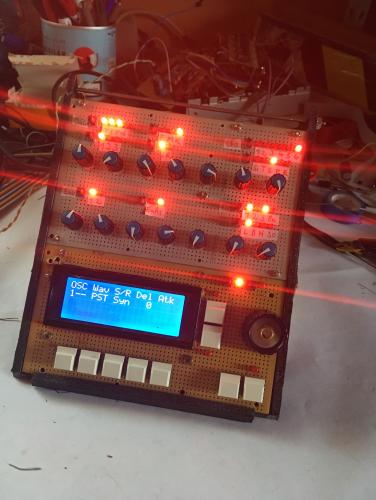
Thank you, it´s still a cardbox with cables and pcbs but I´m so glad all connections work...
-
 1
1
-
-
Ok, that means I really just have to change some lines but as I said I did not get the program chain working and I don't really know if I need to install all the stuff because this looks like installing stuff for realtime editing via mios studio. So I thought I just could open the asm file with the microchip ide and I need to include some files...
Whatever, one other way I imagined was to translate the lines to hex and just exchange them but this did not work because the translation was not "satisfying"
But if this the one and only way as it is described in the mios manual and still not obsolete ok, I will try to go trough this hell, again.
-
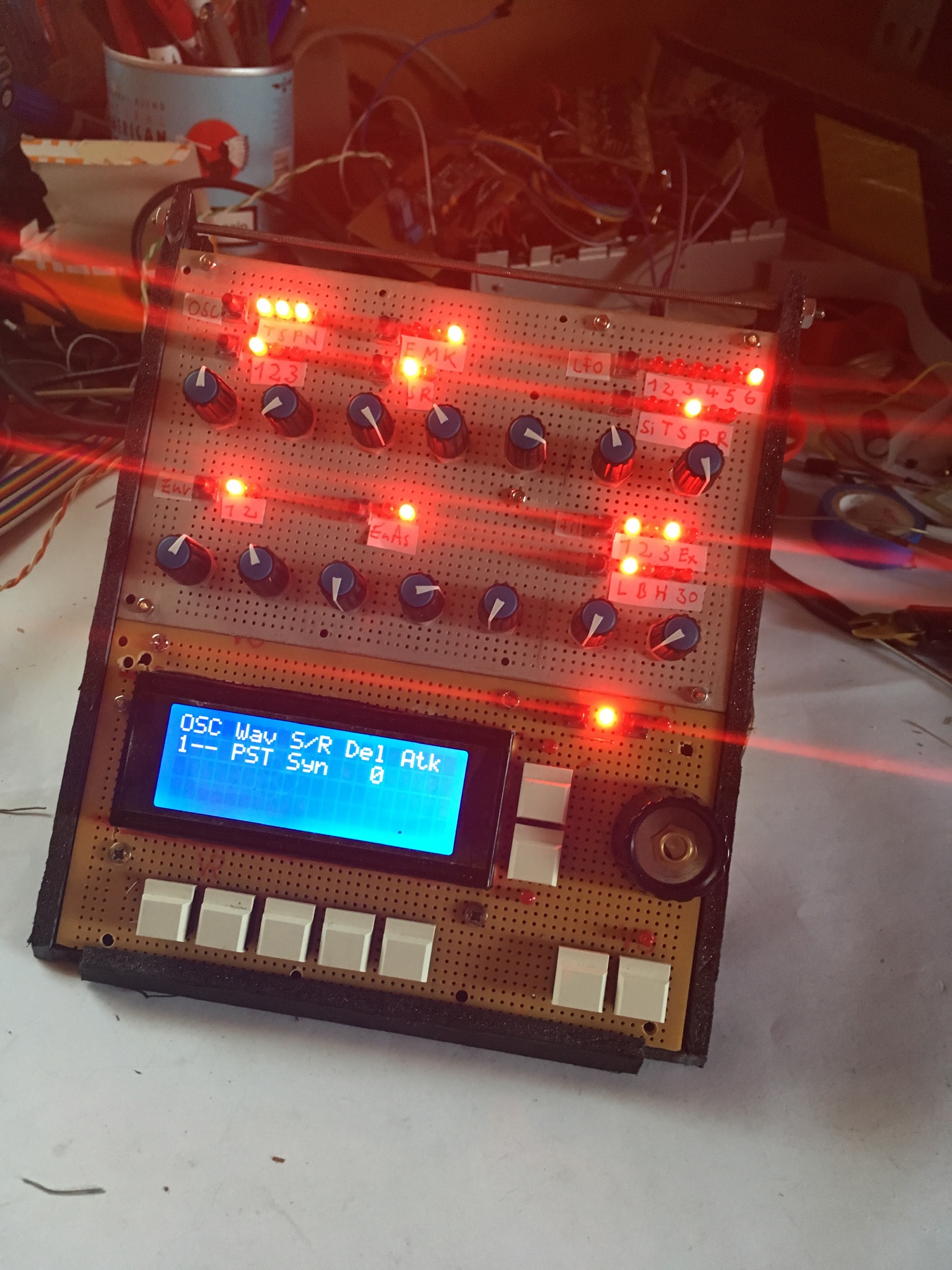
My MBSID is now ready to work.
Unfortunately I found out now that a 4x20 lcd is just supported by the wilba and the classic mbsid just supports a 2x20 by default "fimware"
(Its also cheaper than a 2x20)
I still struggling with programming, I tried to setup the win7 chain but I stucked as I couldn't activate some plug in settings as described and gave up.
I want to set it up at my mac but I'm not sure if the manual is still working with mojave.
Some things are also not clear to understand for me.
Do I just have to change the program line for initialising a 4x20 or do I have to crawl in the wilba code and copy/redesign the lcd code for showing up all the stuff?
If it would be so easy to just change a line would be someone so kind to edit the code for me?
-
It is normal that the Menu behaves like a "back" or more like an "escape" key. I don't know why the others won't work.
-
18f452 is for sid v1
Have you checked if all connections are good? If you use more than one dinx than built one more and check again.
-
1
-
-
I own some stacks of the old one sided pcbs from mikes-midishop (the same which are pictured in the documentation) but not the wilba. But shipping inside eu isn't that safe anymore and expensive, too. I have just a good feeling by shipping inside germany.
It depends on your design. It's possible to mix the sids as you want but you need 9v for the 8580 and 12v for the 6581 and 1 core can manage 2 sid modules (left and right) so both sids get the same controller values. If you want that they work independed, you need a core for every sid. The wilba pcb is a system of 4 hardwired cores and 8 sid slots.
I suggest to get a swinsid and if your setup works, you can get and test sids.
A swinsid is close to a sid but not 100% like a real sid. But cheap and you can use it as 8580 or 6581 by jumper setting.
A 8580 is the newer sid and more precise
The 6581 sounds more dirty and has more bass
-
Probier mal die zu kontaktieren ob sie dir die alte IDE geben können, oder hier im Forum auf englisch fragen ob die Jemand rumliegen hat bzw. in anderen Foren zB Mikrocontroller.net
-
-
Have you tried it without the SID?
-
Try it if you can risk 8$ ;)
-
Are you sure your SID is at full health?
I've got a 6581 with close symptomes but this shouldn't explain the encoders behavior...
-
21 hours ago, Antichambre said:
Hey! This is 20 years thing! TK did it like that for the people who don't know how to program and flash on the PIC. So he created a MIDI bootloader.(Yes there's a bootloader ;)
During some times the PIC was sold with the BL already flashed, then there was no need of a programmer, only a MIDI interface was necessary cause the MIOS8 and the App layer are uploadable with the MIOS Studio, the .hex file! Which is sent as SysEx to the PIC.
I was a bit lost too at the beginning, without any ASM knowledge. But I tried, failed, succeed, and finally learnt a lot more than I expected.
Most of the people don't want to change a line in the code, they just want a working machine after have building it.
Conclusion if you want to change some lines in the code, you must be interested in mios8 and what it is.
Follow the procedures, try, after a few steps, you will see everything lights up. ;)
BR
BrunoYes, I do understand this, it's no accusing, it's complaining ;)
It's not easy to understand and research this in a few minutes, it does need a lot of research...and you don't get the answers easy.
Sooner or later I must do this, just would be nice to have all the 4 rows of my LCD, now. There is just nothing atm I would change with the inputs.
-
Nice.
I tested the PSUs now in case of noise ratio. I can NOT recommend this cheap China PSU it makes a really loud high noise output but the JAZ PSU doesn't do this, it's pretty damn good, I couldn't recognize that the MbSID is powered with earplugs, just after sending some midi note.
Next I will test the power consumption with 1Core LCD and CS stuff, a slave Core and 4 SIDs.
-
I'm at the point now to have to change some stuff, too.
The official procedure looks very complex and I can't really understand why there is a mplab and there is source code in asm, and can't just edit and compile an asm file, and I think it's because I have to include the files in the project and the question is where...and I don't know why this should be so hard.
I don't want to reprogram mios, I just want to change some lines in the code...
-
Pretty much overpowered, but just 1A at the 5v. I also have an old psu which offers 12/5 (0,75/1A), which does more fit the needed power (could be a lil bit underpowered), it's the psu for an Iomega Jaz drive. At ebay someone is selling them in germany but with shipping 30€
As I wrote, I can't recommend those psus at this point because I did not tested it in all ways for a mixed sid setup, I just powered the core and one sid module.
Yes, I use the 5v directly to feed the core and the 12v for the sid.
So the only thing what is to do, is to regulate the 12v to 9. Should be also no problem, but can't say this for sure. I read a thread a few days before here, where smashTV, I guess, has written some words about that there are newer voltage regulators out there in case of having more psu options, today and also describes which capacitors can be removed/changed. Can't find this thread again but just looked inside the sid section.
-
Well, would be better he also paid the shipping if he sells broken psus, but maybe you can get some bucks for the broken one.
May you also have seen that there is a polish company selling new c64 psus on ebay (maybe not in usa), but those are really expensive.
It's unusal that they deliever less volts than 5, normally, if the 5v rail is broken (regulator), it delievers more than that and kills everything inside the c64 what needs just 5v. (rip sid)
Thats why c64 users today building "crowbar" protection stuff inside their psus and the community is still fighting each others solutions. As far as I read the last times...
For a c64, a combination of a 9vac and 5v psu is an alternative and usual but I don't want to contradict latigid on, in case of a midibox you generate 20v ac by a magic act of mixing dc and ac, therefore this solution is profen exclusively at this psus.
I do have some c64 psus but try not to use them.
They may have the best noise ratio, Thorsten wrote, but I want to use a Laptop psu with a 12v and usb 5v rail, it's smaller and you get them for 17€.
I can't recommend them at this point, I still did not tested em in mixed mode but 12 for the sid and 5v for the core, works (yeah, why shouldn't...). The question is still what happens by using the 12v for the old sid and transform this rail to 9 for the new sid.
-
That's not normal, a C64 PSU has 5.20V.
-
2 hours ago, Road_Kill1019 said:
I love forums like this. They so allow me to fully demonstrate my stupidity publicly.
Hell yeah, me too ;)
But next time you read someone, having the same issue, your first question will be…have you uploaded mios? It's better to upload first than to try uploading other stuff, uncessfully...
I can't say if it's written where you have looked, I can't find either a wilba documentation or a sammich. You need to understand that these are one pcb designs which did come later and are based on the modular designs of multiple components and the creators may think, it's logic, you just need to look at the pages which handle the topic.
I red it on the core page, setting up the core, mios8 and there are readmes.
Have fun with your Sammich
-
I'm just sceptic because you did need to install a special driver instead of a default. I'm used to have plugnplay with midi interfaces. Mios Studio worked good with my Win 10 but I don't like it and now my Windows machine has 7, and yeah, in case of old audio interfaces it's also the better choice.
Btw, there is a rumor that if you update your win7 to win10 (by a previous installed 7 and the drivers you need) the possibility is given that those drivers still work under 10 but not if you install them in 10, just if you upgrade.
-
You can read about the "Ready" Information at the LCD module page.
You really need to be sure that your midi interface is working correctly and that it is supported (whitelist) , don't you have a friend or a shop where you can lend (or abbility to give it back) one?
-
I´ve got a theory.
I think the PIC permanently restarts, thats why you get the upload request. Maybe it´s because of the 4,62v, the PIC can start, but breaks down because it needs constant 5v, so starts again...
I must correct what I said about the upload request first, may there is a upload request every seconds BUT you don´t see this.The message:[1355.224] f0 00 00 7e 40 00 0f 00 00 f7 just appears by booting, rebooting the PIC.
-
The voltages seems a bit low, especially the 5v rail, but if your pic work, than it's ok.
The more I think about your problem, I don't think it's the pic.
But as I said, I'm not a pro and it's a pity that no one - maybe also don't have an answer - can say some more.
I know how frustrating it is to stuck and start ordering things which might help, but it is like it is.
What you could do by your own is to build a minimal core setup with a breadboard, so you can exclude connection or wiring mistakes and you also learn what does this and that and so on. It's not as hard as it seems to build the core with midi by your own.
-
Ok, I did the lcd interconnection test. I refused to, because I don't understand what's the difference vs signal checking with a Voltmeter.
But first, results:
Sending 5v at d4 gives me just 1.65v and d5 has 0.8v
Sending 5v at rs = 0.20v
And now, I don't understand why the Voltmeter tells me the lines are not touching each other.. because of touching in a microarea?
Update, solved.
Thank you!
Data lines are more sensitive, right? I removed also the bridge pin 28 to j4.
Also I put in the 1k resistor and diode for can Interface bevor but Im kind of sure it's not necessary for the LCD connection.
Update,
Checked the second Core and rs just gave me, 0.80v. I was kind of sure it´s the connection to r4, cutted the wire and voila.
So, I still did not make an research by my own and maybe I overlooked something but either r4 is removed for the x4685 or I did a mistake.
Edit. Yes I soldered the bridge to the wrong pin at j4 at both cores...shame...sha...
Looking for tight / heavy encoders
in Parts Questions
Posted
You would have resistance :)