TK.
-
Posts
15,248 -
Joined
Content Type
Profiles
Forums
Blogs
Gallery
Everything posted by TK.
-
Hi Robin, could you please try again with the version I released at 18:34 (CET) (somehow I knew that you will face the error before I come back from a nice walk in the autumn sun ;)) Improved velocity support once pins are mapped correctly again. Thereafter you can integrate your own code. Best Regards, Thorsten.
-
P.S.: I changed the scan loop again, so that RC is also pulsed after SRIO shift. Approach: - latch DIN values - read DIN, shift next DOUT pattern - latch DOUT values - period it is possible to omit the second pulse (as we did before), but first I would have to know if the current version is working correctly! (as I cannot try it with real hardware, there is always the risk that I overlook something...) Best Regards, Thorsten.
-
Du hast wahrscheinlich ein Standardschreiben bekommen, in dem immer nach einer Rechnung gefragt wird. Wenn die Lieferung wirklich ein Geschenk war (kommt bei mir des oefteren vor), lasse ich mir vom Absender den Warenwert per EMail bestaetigen (dabei kann man ja ruhig mal ein wenig abrunden...) - die Zollbeamten geben sich damit zufrieden, und berechnen dann auf diesen Wert Zoll und Mehrwertsteuer. Falls Dir das zu heikel ist, zeige ihnen die PayPal-Rechnung und gib an, dass sich der Absender bei der Deklarierung der Ware wohl vertan habe... Gruss, Thorsten.
-
Hi Robin, I think that I found the reason why the row index started from 1 instead of 0. Before the first row was scanned, the selection pattern for row=0 was shifted into the DOUT registers, but it hasn't been latched. Accordingly, the first DIN scan started with the selection pattern for the last row (row=15, which is not connected at your side) Now I'm pulsing RC before the scan is started. At the beginning we will have two pulses, one to latch DOUT values, another to latch the DIN values of the selected row - this is correct and no programming error. so that we would get a notification about the potential programming error. You could please specify the measured delay instead of the velocity value? Because the velocity value is already a result of the formula which applies the delay value. We want to replace this formula, therefore we need the input parameter. Best Regards, Thorsten.
-
At least the MIOS32 implementation of the BLM_SCALAR driver provides equivalent functions: extern s32 BLM_SCALAR_PinSet(u32 colour, u32 pin, u32 value); extern s32 BLM_SCALAR_DOUT_PinGet(u32 colour, u32 pin); extern s32 BLM_SCALAR_DOUT_SRSet(u32 colour, u32 sr, u8 value); extern u8 BLM_SCALAR_DOUT_SRGet(u32 colour, u32 sr); [/code] they don't exists for the MIOS8 variant as I was too lazy for doing this. However, you've direct access to the LED arrays: [code] extern unsigned char blm_scalar_row_red[5*8]; extern unsigned char blm_scalar_row_green[5*8]; which works much faster anyhow. let's assume the pin number is stored in a 16bit variable: unsigned short pin; pin = 0; // as an example) [/code] then you can set a "green" LED with: [code] blm_scalar_row_green[pin >> 3] |= MIOS_HLP_GetBitORMask((unsigned char)pin)); and clear a "green" LED with: blm_scalar_row_green[pin >> 3] &= MIOS_HLP_GetBitANDMask((unsigned char)pin)); [/code] Best Regards, Thorsten.
-
Hi Robin, as mentioned earlier, you will have to change your hardware connections to get the pin numbers matching again. Previously the first pin was in row 1, although the software already started to count from row=0 (so, it was the second row) Just check your DOUT connections, all pins have to be shifted by one. Alternatively try following change: // will be called on button pin changes (see TASK_BLM_Check) void BUTTON_NotifyToggle(u8 row, u8 column, u8 pin_value, u32 timestamp) { row -= 1; // we don't know why rows are starting from 1 on Robin's Hardware [/code] Best Regards, Thorsten.
-
I updated the files so that they are matching with your pin table. And I copied the .doc file into the doc/ folder. Probably you have to change some matrix connections on your hardware if this hasn't been done yet. To determine a suitable logarithmic curve it would be interesting which delay you measure for different pressures, e.g. "hard", "normal", "semi", "soft", "very soft" - and which velocity values should be output in such cases. Best Regards, Thorsten.
-
Seems that you haven't installed the arm-none-eabi-gcc toolchain yet. See also this document: http://svnmios.midibox.org/filedetails.php?repname=svn.mios32&path=%2Ftrunk%2Fdoc%2FMEMO resp. this Wiki page: http://www.midibox.org/dokuwiki/doku.php?id=installing_gnu_on_osx Best Regards, Thorsten.
-
Following variables have to be set in addition: export MIOS32_FAMILY=STM32F10x export MIOS32_PROCESSOR=STM32F103RE export MIOS32_BOARD=MBHP_CORE_STM32 export MIOS32_LCD=clcd [/code] Best Regards, Thorsten.
-
Hi Robin, I'm glad that the code is working, although I never had the chance to test it by myself. Your descriptions and comments made it easy to follow the progress remotely! :) Using different methods (e.g. faster scan speed, faster update cycle, using DMA) will lead to a lot of extra work for that I think it isn't really worth the effort! From my experience I can already say that this won't improve the results, and Duggle confirmed this in his comment. By scanning the complete matrix within 1 mS you've already a very optimized version, with common MIOS32 SRIO driver it would normaly take 16 mS (since a single DIN pair of the matrix would be scanned each mS) which is slower than the shortest possible delay. Now you've a version which scans faster than the shortest delay. To your table: could you please also count the pin numbers from 0 instead from 1? This would simplify the documentation as well, because currently I had to add some comments into the source code to explain the difference, which might be confusing. Starting note: ok, will be changed to 0x15 Velocity curves: good point! It could make sense to apply a logarithmic curve, so that short delays lead to higher differences than long delays - I will check later today (or tomorrow) if it's possible to calculate the curve during runtime instead of using a pregenerated table to allow finetuning w/o recompilation. Best Regards, Thorsten.
-
Yes, exactly! :) I'm using following formula to determine the velocity value: // determine velocity depending on delay int velocity = 127 - (((delay-KEYBOARD_DELAY_FASTEST) * 127) / (KEYBOARD_DELAY_SLOWEST-KEYBOARD_DELAY_FASTEST)); // saturate to ensure that range 1..127 won't be exceeded if( velocity < 1 ) velocity = 1; if( velocity > 127 ) velocity = 127; [/code] So, the minimum and maximum delay is scaled to a velocity value between 1..127 The constants are defined in the header: [code] #define KEYBOARD_DELAY_FASTEST 3 #define KEYBOARD_DELAY_SLOWEST 100 If you notice different min/max delays, just change these constants (and let me know so that I can insert them into the original file) Note that you could try to play a software synth with your keyboard now. It's also possible to control a common MIDI device, just replace: #define KEYBOARD_MIDI_PORT DEFAULT [/code] by: [code] #define KEYBOARD_MIDI_PORT UART0 and MIDI events will be sent to the MIDI OUT1 port of the MBHP_CORE_STM32 module. Best Regards, Thorsten.
-
Note Off events: stupid error from my side, these events should be sent now. Velocity: it would be important to know which delays have been measured (messages should be short enough now) Best Regards, Thorsten.
-
Ok, it seems that the code is working (are MIDI events sent? The MIDI IN Monitor of MIOS Studio should show them), just the debug message which will show the delay was too long. Could you please try the updated version? Best Regards, Thorsten.
-
I added another debug message, could you please try again? Best Regards, Thorsten.
-
Thanks Robin, the informations were really useful to understand the mechanism! The updated version can now be found in the repository: http://svnmios.midibox.org/listing.php?repname=svn.mios32&path=%2Ftrunk%2Fapps%2Fexamples%2Ffastscan_button_matrix_16x16%2F The comments should be sufficient to understand how I implemented the "simplified" state machine. Some more debug messages are print, the velocity is calculated and a note on/off events should be sent. It would be interesting if this routine is working correctly, and if not: which debug messages are print when a key is pressed/released. Best Regards, Thorsten.
-
As Nils wrote: on a reply, please remove the text between the quote tags, it doesn't need to be duplicated (as you would normaly do when replying to an email) Could you please write some comments between the debug messages, because I'm unable to find out, when you pressed a key, when it has been released. Somehow it looks like the keyboard isn't connected correctly, because I would expect that one contact is closed when the key is pressed, another is closed when the key is not pressed. Only this will allow to measure the delay correctly. In other words: the two pin_values should alternate between pressed/depressed, they shouldn't have the same value. Best Regards, Thorsten.
-
For those who haven't noticed this yet: sounds like a great deal! :) Best Regards, Thorsten.
-
Hi Robin, let's do some additional experiments before deciding if the pins have to be scanned faster, and accordingly a timer function has to be used instead of a FreeRTOS task. It's also not clear yet, if the scan gets unstable if SPI is clocked faster - it could be that you won't notice any difference, as only two DINs and two DOUTs are connected. All these assumptions are based on theoretical thoughts, the final result could be much easier that expected! :) You will find an enhanced version in the respository now which decodes the pins according to your table. It also measures the delay between pin events. -> http://svnmios.midibox.org/listing.php?repname=svn.mios32&path=%2Ftrunk%2Fapps%2Fexamples%2Ffastscan_button_matrix_16x16%2F It would be interesting if the pin numbers are calculated correctly according to your table (I tried to program the required bit-shifting on an easy-to-read way, therefore a bit more code is required, but the compiler will optimize it anyhow so that performance isn't affected) Then the measured delays are for interest of course. Please show us the MIOS terminal output when a key is pressed fast (so that a high velocity value should be generated), and very slow (for the lowest velocity) It's important to see the timestamps/delays for a 1->0->1 transition of both pins (6 debug messages) Best Regards, Thorsten. P.S.: the "status" variable was just an artifact, I removed it
-
Access to programmers lounge should work now - have fun! Best Regards, Thorsten.
-
Problem: STM32 hasn't enough internal RAM for a proper C64 emulation which is required to playback a .sid file. Possible solution: dump any SID register change and delays between register writes to a file - this can be streamed from a SD Card and forwarded to the SID(s) The same mechanism can be used to playback samples. Best Regards, Thorsten.
-

Simple Transport controller for Ableton/logic/protools?
TK. replied to Googleberry's topic in MIDIbox HUIs
Here is the "meta thread" - would be nice if you could help to keep it up-to-date, because it seems that it hasn't been updated for 4 years http://www.midibox.org/dokuwiki/doku.php?id=forum_highlights Best Regards, Thorsten. -
The MIOS32 variant of BLM_SCALAR firmware is ready for use: http://svnmios.midibox.org/listing.php?repname=svn.mios32&path=%2Ftrunk%2Fapps%2Fcontrollers%2Fblm_scalar%2F It works exactly like the PIC based version, but provides USB in addition (for those who are interested ;) For your usecase, just remove the code inside DIN_BLM_NotifyToggle() and APP_MIDI_NotifyPackage(), and add your own button/led handler Best Regards, Thorsten.
-
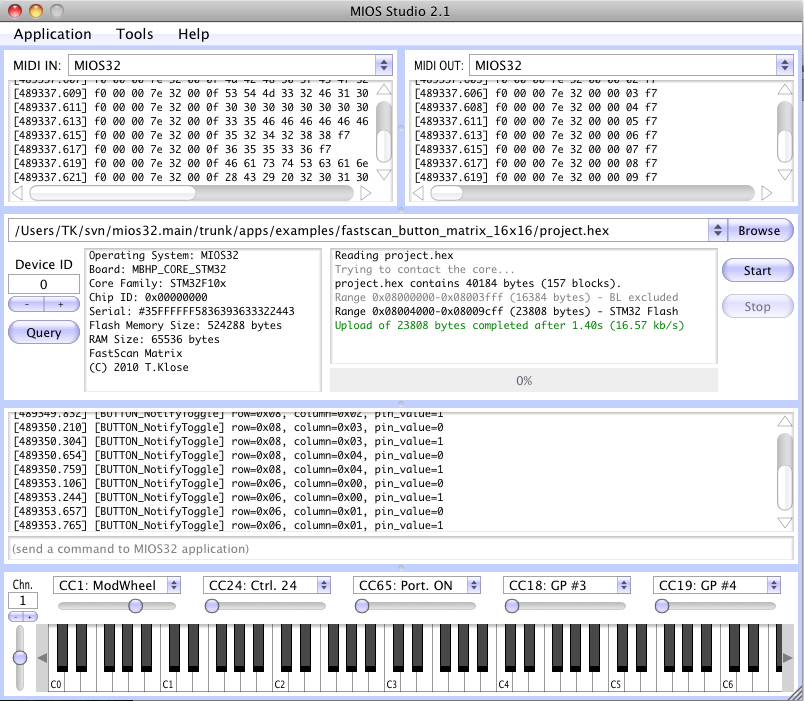
Alright, here the application: http://svnmios.midibox.org/listing.php?repname=svn.mios32&path=%2Ftrunk%2Fapps%2Fexamples%2Ffastscan_button_matrix_16x16%2F You have to update the complete repository, because I added a new switch (MIOS32_DONT_SERVICE_SRIO_SCAN) to programming_models/traditional/main.c It's set in mios32_config.h and disables the scan routine which is used by MIOS32 Instead we use our own scan routine now, In order to keep it simple, we use MIOS32_SPI_TransferByte() accesses directly without DMA and without callbacks. It's fast enough for your usecase. The TASK_MatrixScan() task handles the transfers and calls BUTTON_NotifyToggle() whenever a change on the DIN pins has been determined. This task performs the scan each mS - which means in other words, that the worst-case latency is 1 mS which should be acceptable. My scope tells me, that the 16x16 scan takes 400 uS (*), which means that the core is loaded by ca. 40% and could do (many) other things in parallel... (*) speed could be significantly improved by selecting a faster SPI clockrate, but for your usecase the current speed setting is acceptable (and it leads to more robust results!) BUTTON_NotifyToggle() will be informed about the row, column and pin_value They will be print in the MIOS terminal like shown in this example: Once we know, in which rows and columns the keyboard keys are located, a note number can be derived - either table or calculation based. But for the first experiments the debug messages will be mored helpful. unconnected pins won't cause a problem. Best Regards, Thorsten.
-
I think that the easiest way to clarify this is a small example application which is tailored for your usecase - I can program this :) But I would have to know how your keyboard is connected to the DIN/DOUT registers - did you already document this somewhere? Best Regards, Thorsten.
-
It's never to late, as we are always able to order new batches :) Current state: we got 10 black cases. Unfortunately they were a bit more expensive than expected (overall costs ca. 75 EUR per piece, this includes taxes, shipping Heidenreich->Nils, etc..) Next week I will know the costs for a batch order with >= 50 cases - they should be less expensive. Best Regards, Thorsten.