

TK.
-
Posts
15,248 -
Joined
Content Type
Profiles
Forums
Blogs
Gallery
Everything posted by TK.
-
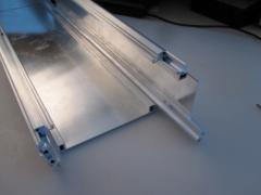
From the album: TK: MBSEQ Aluminium Case
This picture demonstrates the construction system nicely. :) -
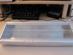
From the album: TK: MBSEQ Aluminium Case
Note that there are some "movable slides" (or how you would call them) which would allow to mount the frontpanel with screws. -
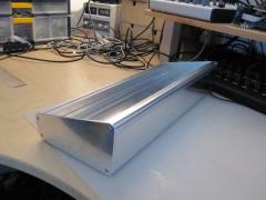
From the album: TK: MBSEQ Aluminium Case
From the other side - the case looks very robust! -
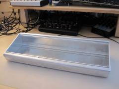
From the album: TK: MBSEQ Aluminium Case
The prototype consists of untreated aluminium. I prefered this option due to the faster delivery. The final case will be black anodized aluminium -
Following orders have been shipped today: orgelman dcer10 (via Nils) phunk skennedy Following orders will be shipped next weekend (once I got the money...) ssp runinit potain Best Regards, Thorsten.
-
Mouser berechnet auf dem Gesamtpreis eine VAT. Wie die sich genau zusammenstellt ist nicht ganz transparent. Doch sie liegt i.d.R bei ca. 21..22% - insofern stimmt das mit Seppos Erfahrungen ueberein (19% + X) Auch den schnellen Versand kann ich bestaetigen - nach 2 Tagen steht der Fedex-Mann vor der Tuer (und i.d.R. am naechsten Tag schon wieder, da Fedex zu unmoeglichen Zeiten liefert) Leider ist mein Bedarf momentan ebenfalls gedeckt - vielleicht im Winter wieder :) Gruss, Thorsten.
-
wegen des Pull-Up Widerstands solltest Du am RX Pin auch ohne den PIC ca. 5V messen - wenn das nicht der Fall ist (ich bin bei meinen vorigen Aussagen davon ausgegangen...), dann liegt das Problem woanders. Verfolge mal mit dem Messgeraet saemtliche Leiterbahnen die 5V und Masse fuehren. Irgendwo hast Du eine Loetstelle vergessen, oder die Leiterbahn ist beschaedigt. Wenn der TX Pin auf 5V geht, laeuft der PIC. Ohne Programmiergeraet gibt es keine andere Moeglichkeit. Um eine Vss (Masse)-Verbindung zu ueberpruefen, schliesst Du den Plus-Pol Deines Messgeraets an einen 5V Pin (bspw. J2:Vs), und greifst mit dem Minus-Pol die Spannung an der Vss Leiterbahn (bzw. an dem Pin) ab. Gruss, Thorsten.
-

MBHP_ETH, MBHP_SDCARD, SSM2044, SSM2164 PCB Bulk Order
TK. replied to seppoman's topic in Bulk Orders
fixed Best Regards, Thorsten. -
Should get his nice looking MBSEQ V4 metal desktop case prototype in ca. 3 weeks - feel prepared for a bulk order! :-)
-
Nein, an TX solltest Du keine Spannung messen, wenn der PIC nicht eingesetzt ist. An RX misst Du in diesem Fall wegen des Pull-Up Widerstands R6 ca. 5V Wenn die Spannungen an den Vdd/Vss pins passen, kann es eigentlich nur noch an der Oszillatorschaltung (C1/C2/Q1) liegen - oder der PIC wurde nicht sauber geflasht (-> der MIOS Bootloader laeuft nicht an) Gruss, Thorsten.
-
W/o the risk for drifting too much into an off-topic discussion: two years sounds realistic - not to complete all of your vague ideas, but at least to find something which works at your side. And I'm sure that you will gain a lot of experience by starting from scratch. :) Have fun and don't hesitate to ask for details if something is unclear or not working, and/or to share your code (write permission to the subversion server is available for all programmers) Best Regards, Thorsten.
-
Thanks for the introduction, now I understand why you asked this question. Welcome to the wikipedia generation! ;) It will be hard for you to find an explicit answer in the internet, since a DMA peripheral is used for multiple purposes. There are differences between chip families and there are different usecases. You probably know from your AVR history, that as long as the CPU handles a data transfer with the polling method, it would get frequently interrupted by interrupt service routines. As a result this reduces the bandwidth. Even interrupt based transfers can block each other, they lead to unwanted dependencies (-> complex, inflexible, intransparent, timing critical, hard to maintain code) and they reduce the performance of the main thread(s). In the MIOS32 specific context you have to consider that functions are running in FreeRTOS based threads that are timespliced. By using a DMA (which you probably don't known from AVR controllers) data transfers will be handled in background >>immediately<< w/o using the CPU. A CPU thread typically waits until the complete transfer (with a definable number of bytes) has been finished. While doing this it can be interrupted by other threads/ISRs - but the bandwidth won't be affected. Nils is still our No#1 layout slave and deserves my full trust! :) Your idea doesn't sound so unusual to me. If you would know my applications better, you would know that the concepts are already available (e.g. search for MBNET and the appr. source codes - it exists for "low-cost" PICs and STM32), resp. that complete applications already exist. The reason why I don't "sell" this as a "workstation concept" is just that I know that people would expect a bit more than just some programming experiments, but a complete "plug&play" infrastructure for cheap money, similar to Yamaha MLAN. What I can already tell you: such a infrastructure will cost a lot of money (since multiple chips are involved), a lot of programming effort and at the end also chip resources (more flash/RAM memory for higher flexibility during runtime) The art (and you will see this point in 10..20 years) is to create a simplified infrastructure which doesn't support everything, but which makes most people and especially yourself happy, for as less money as possible with as less effort as possible. But I don't really want to reduce youthful enthusiasm - maybe you will find a clever solution which hasn't been found by somebody else before by working on a high-level approach based on existing concepts, and/or just by ignoring any objections! :) Best Regards, Thorsten.
-
Hi, Not yet, but soon. Only the USB driver has to be overworked due to the new peripheral version. It's hard for me to explain you the details if I don't know your background knowledge. Could you please introduce yourself first, tell something about your skills and what you already realized before so that it's easier for me to give you individual help? A chip select line can be located at any free IO pin. There are so many different applications that I'm sure that you won't find any free pin which is not allocated by any of them ;) Therefore pins (and SPI ports) are usually mapped via #define statements that can be overruled in a mios32_config.h file The next MBHP_CORE_STM32 module (planned for next year) will use at least a 100 pin device. More details about such topics can be found in the programmers lounge. I already gave you access to this hidden forum section. Best Regards, Thorsten.
-
Hallo, 4.6V ist ein wenig niedrig, doch noch im erlaubten Bereich. Wie hoch ist eigentlich die Spannung an J1? Am besten verfolgst Du nun mit Deinem Messgeraet die Leiterbahn zwischen dem Tx Pin und der restlichen Schaltung - siehe Schaltplan: http://www.ucapps.de/mbhp/mbhp_core_v3.pdf Vielleicht ist Pin #25 nicht richtig verloetet, oder zwischen diesem Pin und dem MIDI Ausgang befindet sich aufgrund eines Loetfehlers ein Kurzschluss nach Masse? Gruss, Thorsten.
-
SD Card and Ethernet are usually connected to J16. It is possible to connect a third device, but it should be clear to you that this slows down the overall performance of your application. J8/9 would be an alternative solution - you haven't listed DIN/DOUT, so this port is free. You would use the MIOS32_SPI* function to configure the SPI interface: http://www.midibox.org/mios32/manual/group___m_i_o_s32___s_p_i.html Configuring SPI for ca. 10 MHz clock isn't a problem (-> MIOS32_SPI_PRESCALER_8) MIOS_SPI* transfers data via DMA, so that this clock rate indeed improves the performance. Interrupt line: check which pins are free on your board, search in the STM32 datasheet for possible routings. On the other hand: I would prefer STM32F105x for this usecase. It has two integrated CAN controllers, and there is no conflict with USB. Accordingly the transfer performance will be much better, and the complexity will be reduced -> improved robustness. Disadvantage: it only has 256k flash maximum (yet) But since you are planning to split tasks over multiple chips anyhow, this shouldn't be a problem for you. Best Regards, Thorsten.
-
I guess that the blue "Luftpost" priority sticker speeds up the delivery dramatically! :) Following orders have been shipped today: drsyncenstein julianzizko chrisbob12 pataroulis lameth Joe56 Wild_Weasel Lu Taska grizz zen_audio kaleaf sunflower rhinoceros gomiboy99 Acidtracker shipped via Nils (soon): dcer10 Following orders will be shipped next weekend (once I got the money...) ssp runinit potain Best Regards, Thorsten.
-
With the session concept the format function under UTILITY->DISK got obsolete, therefore I removed it from the application (but haven't updated the documentation yet). E3 means that the volume information (part of the filesystem) couldn't been read E11 means, that a file couldn't been written Probably E11 is a side effect of E3 - means, there seems to be an issue with the format. Phil has created an application which formats a SD Card properly, it can be found here: (please continue discussion there) Best Regards, Thorsten.
-
Some informations are located in the hidden programmers section: Some others in a german thread: therefore you haven't got useful hits with the search function. Please keep us updated - you could create a blog to document your experiments, this would result into a handy link for me to give other people some more informations about this topic. I keep my own documentation effort low by setting the "not more than 16 DINs/DOUTs" rule ;) Yes, using multiple SPI ports would solve this as well. Best Regards, Thorsten.
-
Hi Doug, It's hardcoded in mios32_srio.c, but already configured for the lowest frequency. However, reducing the clock rate won't allow you to extend the chain, because the impedance is the parameter which limits the length! A refresher (I wrote about this multiple times in the forum, therefore only the reduced summary): See this snapshot (measured on a PIC with a superlong SRIO chain, but for STM32 it would look similar): The transients on SCLK line overshoot VH/VL, this will lead to non-deterministic clocking of the serial registers. For STM32 the situation is even more critical if SPI pins are configured for push-pull mode, where signals are working at 3.3V Therefore I decided to configure the pins for open drain mode, and to pull the signals to 5V. This results into such sexy curves: But experiments showed me, that the Logic-0 and 1 get above/below the threshold levels of the HCT chip family once more than 20 DINs and DOUTs are chained. Yes, using buffers will cost you some additional chips, but it will help. Take care that SCLK/RCLK have to be buffered separately for DIN/DOUT chain. And buffers should be integrated along the chain, don't use starlike wiring, because this can result into setup/hold violations caused by unbalanced delays between FF clock and input! Buffer IC: I tried a 74HC541 some time ago - it works, but has more buffers than really required (as mentioned earlier, starlike wiring, resp. using one buffer IC to distribute the SCLK for all DIN/DOUT chips is not recommented) There are probably similar chips with lower pin-count If you've SMD soldering experiences, such an option would be preferred Best Regards, Thorsten.
-
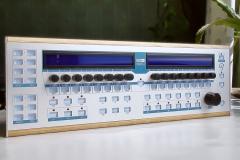 wow! Great choice of colors and nice buttons! :)
 -
The usage of serial registers give us the advantage that remaining IOs are free for other purposes. Since most of bigger applications get use of all available pins, SRIO is the first choice and therefore the standard. (*) Scanning the SRIOs doesn't really take that much CPU time, as MIOS32 handles the (hardware) SPIs via DMA transfers in background. While the complete SRIO chain is scanned, the CPU is doing something else. Therefore the serial clock rate doesn't matter (I selected a slow clock rate to make the transfers more robust). Only the propagation of pin changes to the application takes CPU time, but a handler for parallel IOs would have to do exactly the same! Note that it is possible to call MIOS32_SRIO_ScanStart() from the application to scan the SRIO more frequently. This will require to remove the MIOS32_SRIO_ScanStart(SRIO_ServiceFinish); call in vApplicationTickHook - I could add a #ifndef based switch if you want, so that this code doesn't need to be modified. Instead you would enable this switch in your mios32_config.h file, and call MIOS32_SRIO_ScanStart from a timer function (-> MIOS32_TIMER) embedded into your app.c file at the desired frequency. I don't see the need to integrate an alternative method into MIOS32, but nobody prevents you (or somebody else) from writing a driver for parallel scanning and to put it into $MIOS32_PATH/modules so that other applications can access it. In difference to MIOS8, MIOS32 is very modular (e.g. it's possible to remove the software parts which scan the SRIO chains from the binary). Or to disable the default scanning method and to do it on a different way (e.g. more frequently) as described above. Everything which is special and not used by most of the applications should be located under $MIOS32_PATH/modules This has the advantage that multiple solutions for the same "function(s)" can be provided and selected by the application. You are writing that there isn't a MIOS32 equivalent to STM32F10xgpio c This isn't completely true - because this driver provided by STM is already compiled into each application (the sources are here) so that you can already use these functions w/o Makefile modifications. You are even able to re-use most of the example applications provided by STM for the first experiments if you remove the system initialization parts that are mostly located in the main.c file of these examples (because the system is initialized by MIOS32_SYS_Init) Best Regards, Thorsten. (*) another reason for using SRIO is, that they are working at 5V level instead of 3.3V, and that 74HC595 can drive multiple LEDs w/o loading the microcontroller. This isn't relevant for your plans, but I think that I should highlight this to make clear why SRIO is better for most applications.
-
Shipped today: rmouneyres michael123 afx socrates antix Napiks meimaddin reincarnate glacial23 efluon altitude jrock keyg artyman henk gomiboy99 tamiflu paulb Buriedcide Boops shipped via Nils (soon): dcer10 Following orders will be shipped next friday (once I got the money...) julianzizko lameth ssp Joe56 runinit Best Regards, Thorsten.
-
I described the details somewhere in the forum, but I'm too lazy to use the search function. ;) Changing channels: can be done via CCs CCs can be sequenced. CC Layers are stored in a track. So: yes, it's already possible. Best Regards, Thorsten.
-
I will ship already paid GM5 orders probably this Thursday. Next shipping day would be friday next week. The ordering procedure is described in the Wiki: http://www.midibox.org/dokuwiki/doku.php?id=tk_gm5_bulkorder Best Regards, Thorsten.
-
Gridracer: your idea isn't lost - I like it and will see what I can do. Echopraxia: the recommended method is to store the complete track from which the drum map should be exported into a preset (MENU->EVENT->PRESET->SAVE AS NEW PRESET) Now you can import the drum map into another track with the PRESET function as well. Note that you will be asked for several import options, e.g. you can exclude the pattern import (Steps: no), etc. This function not only works for importing/exporting drum maps, but for anything related to a track. It's the most powerful copy function (especially since you are able to edit preset files with a text editor) - you will like it! :) Best Regards, Thorsten.