TK.
-
Posts
15,248 -
Joined
Content Type
Profiles
Forums
Blogs
Gallery
Everything posted by TK.
-
The distance between DIN7 and MIDI connectors is not correct, it seems that you added the size of the clip at the left side by accident: Best Regards, Thorsten.
-

MIDIbox of the Week (MIDIbox SEQ V4 of sineSurfer)
TK. replied to sineSurfer's topic in MIDIbox of the Week
I must say that I'm really impressed about this nice woodwork - very well done! :) Once I got the wordpress blog fixed, I will publish the pictures :) Best Regards, Thorsten. -
MBSEQ V3 stores global settings (which are not part of a pattern) into internal EEPROM, address 0xf0000200 upwards. No configuration data is stored in flash. You are using the SysEx request for a PIC18F452 which only contains 256 byte. For the 1k EEPROM of PIC18F4620 following request should work: F0 00 00 7E 40 00 01 20 00 01 00 F7 Best Regards, Thorsten.
-
The long summer break is over and I continued with MBSEQ development :) Beta24 is available now: o support for OSC (requires MBHP_ETH module) 4 OSC ports are available, currently they only send MIDI packets. A MIDI<->OSC proxy is currently only available for MacOS (on request) An easy to use Juice based Proxy is planned and will be released soon. (Firmware-)configurable OSC packets will be available in one of the next releases. o new network configuration page for the MBHP_ETH module o the debug terminal now supports a "network" command to retrieve the current status of the network configuration. o now we have global configurations which are stored independent from the session configuration in the "/MBSEQ_GC.V4" file Following parameters have been moved to this file: - MetronomePort - MetronomeChannel - MetronomeNoteM - MetronomeNoteB - RemoteMode - RemotePort - RemoteID - BLM_SCALAR_Port - ETH_LocalIp - ETH_Netmask - ETH_Gateway - ETH_Dhcp - OSC_RemoteIp - OSC_RemotePort - OSC_LocalPort o probability parameter now incremented correctly in edit page o if the track plays multiple notes, gate is only cleared if all notes are set to "---" o BLM: triggers now displayed correctly in all stepviews [/code] The new network configuration page can be found at the end of the menu pages list (press EXIT button, scroll the list to the end) One issue isn't fixed yet: you will find it in the TODO list at the end of the CHANGELOG.txt file. Here some technical notes: [code]The handling of loopback tracks differs from normal tracks. MIDI Events are sent immediately to the transpose/arpeggiator function instead of using the scheduler, so that note changes take place immediately and independent from the track number before new MIDI events are scheduled. Disadvantage of this method: note off events won't be generated, accordingly the gatelength won't be considered and HOLD/RESTART of transposed tracks won't work as expected. Possible solution: gatelength counter for note off events, only used for loopbacked tracks. Problem: how should polyphonic loopback tracks be handled? It could be sufficient to call SEQ_MIDI_IN_ResetTransArpStacks(<bus-number>) depending on the gatelength So - a proper solution will need some time, because I'm currently not sure about the side effects. Best Regards, Thorsten.
-
Please move the BLM connector to the left side of the PCB! :) (-> right side of the backpanel) Best Regards, Thorsten.
-
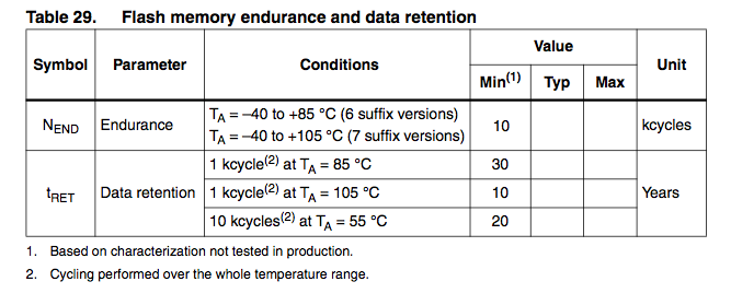
According to the datasheet STM guarantees 10k cycles at typical conditions (55°C) for 20 years Best Regards, Thorsten.
-
Not yet, but currently it isn't relevant. It's only important that the socket can be mounted and soldered. You could add a 7-pin SIL header, the connections can be defined later (there is no equivalent socket on the core module anyhow, cables have to be soldered directly at different places) This socket could be used for other purposes as well by people who don't own a BLM. yes, thats allow. yes Best Regards, Thorsten.
-
Nice idea, I'm interested on a board for my MBSEQ :) Proposals: Currently the jumper settings are ID 10, 12, 14, 16 - I would place the first IIC port at the right, and the last IIC port at the left side (ID 16, 14, 12, 10), so that the ports numbers are in the right order if you look to the sockets from the backpanel side if people don't like this order, just add the jumpers again ;) if no jumpers are required, you could also leave out the pull-up resistors and clamp the appr. ID pins directly on Vdd (+5V) would it be possible to consider a 5th DIN socket (but with 7 pins) at the left side for an optional BLM connector? Distance between the IIC sockets and the BLM socket should be one "left out" socket distance between mounting holes and "socket side" should be at least 20 mm (like on the MBHP_CORE_STM32 module), or better: 25 mm for compatibility with the MBSEQ aluminum case add 2 additional mounting holes at the other side for more robustness (it's worth the PCB area) make jumper J2 compatible with J4 of the core module (the middle pin is used for a receive interrupt, but the MIDI IN option isn't used anyhow) See also my backpanel as reference: http://www.ucapps.de/midibox_seq/mbseqv4_backpanel.png Best Regards, Thorsten.
-
Hi, considered that bit #6 will be set on values >= 64, you could write: movlw 0xb0 call MIOS_MIDI_TxBufferPut movlw 0x53 call MIOS_MIDI_TxBufferPut movlw 127 btfss this_value, 6 ; bit 6 is set on values >= 64 movlw 0 call MIOS_MIDI_TxBufferPut [/code] Btw.: you split the range between 0..62 and 63..127, but it's better to split it at 64, since it's exactly the half of the value range. Best Regards, Thorsten.
-
No, I don't have the old code anymore !!!!!! But probably it looked somehow like this one ?????? void ROUTER_Rx_IIC3(unsigned char ptype, unsigned char evnt0, unsigned char evnt1, unsigned char evnt2) __wparam { unsigned char transposed_note; // IIC3: connected to my Yamaha AN1x // lock/release this routing path on SysEx streams ROUTER_LockPathOnSysEx(PORT_IIC3, ptype); // filter clock if( evnt0 == 0xf8 ) return; // apply exactly the routing as documented under http://www.ucapps.de/midi_router/midi_router_default.gif // note: parameters selectable on the UI are not taken into account here // if this is desired, replace constants by router_flags.* variables as in the original router.c file if( ptype >= 0x08 && ptype <= 0x09 ) { if( (evnt0 & 0x0f) == MIDI_CHN16 ) { if( evnt1 < 0x3c ) { ROUTER_Tx_IIC0(ptype, (evnt0 & 0xf0) | MIDI_CHN9, evnt1, evnt2); transposed_note = evnt1 + 2*12; // if value >= 0x80, decrement 12 until we have reached the range <= 0x7f again while( transposed_note & 0x80 ) transposed_note -= 12; ROUTER_Tx_IIC2(ptype, (evnt0 & 0xf0) | MIDI_CHN1, transposed_note, evnt2); } else { ROUTER_Tx_IIC1(ptype, (evnt0 & 0xf0) | MIDI_CHN13, evnt1, evnt2); } } } // forward data (also) to the Core MIDI OUT #if 1 // if no FE if( evnt0 != 0xfe ) #endif ROUTER_Tx_INT0(ptype, evnt0, evnt1, evnt2); } [/code] Best Regards, Thorsten.
-
Yes, the released code always contains the current routing I'm using by myself. I don't see a need for keeping the diagram up-to-date, since every user would adapt the routing for his own requirements anyhow. I'm not sure if you are asking for somebody who programs the code for you, or if you just only wanted to mention the differences. If you need a different implementation, you could consider to customize the routing as you really need it - the routing in the diagram is only an example, there are many more possibilities. Best Regards, Thorsten.
-
Good to know that this is really not related to a firmware issue (I already feared that my AOUT_NG is somehow different from others...) Attached you will find a modified version of the mbhp_core_stm32_module IO check application. Before upload remove the AOUT_NG module from J19. I reduced the list of pins which are checked to J19 IOs: static const io_pin_t io_pin_table[] = { { "PB5", GPIOB, GPIO_Pin_5, (1 << EXPECTED_FAIL_IPL) }, // On-Board Pull-Up connected { "PB6", GPIOB, GPIO_Pin_6, (1 << EXPECTED_FAIL_IPL) }, // On-Board Pull-Up connected { "PB7", GPIOB, GPIO_Pin_7, 0x00 }, { "PC13", GPIOC, GPIO_Pin_13, (1 << EXPECTED_FAIL_IPL) }, // On-Board Pull-Up connected { "PC14", GPIOC, GPIO_Pin_14, (1 << EXPECTED_FAIL_IPL) }, // On-Board Pull-Up connected }; [/code] It automatically detects shorts on the board and sends error/debugging messages to the MIOS terminal (-> MIOS Studio). Checks will be done with a period of 5 seconds (not immediately) And now the trick: just use a cable between Vss and a J19 data pin to force a short - the application should notify this. If you don't get a notification, you know that the connection between STM32 and J19 doesn't exist (-> open, e.g. bad soldering) If you always get a notification for certain J19 pins, you know that there is a permanent short (-> check solderings between these pins) Best Regards, Thorsten. j19_check.hex
-
I knew that somebody will request such a mode sooner or later ;) No, such an option isn't supported yet, and I'm unsure if I really should add this to the firmware, or if people could just use existing Max/MSP patches to access the BLM directly for highest flexibility. Best Regards, Thorsten.
-
Of course - just try out some examples from this page: http://www.ucapps.de/mios8_c.html E.g. Sending MIDI events on button movements Controlling 128 LEDs via MIDI Sending 7bit MIDI events on rotary encoder movements Printing values on a LCD You can combine these examples to a bigger firmware and you could also adapt it for your own controlling requirements of course. You won't need a Core32 for such experiments, and the 32k flash of PIC18F452 should be sufficient for your firmware. It's really worth a try (as Ilmenator highlighted) :) Best Regards, Thorsten.
-
Hi, the vector table pointer is set in MIOS32_SYS_Init() The same function is used for Bootloader and Applications; the vector itself will be defined in the .ld file for highest flexibility (e.g. the application could locate the vector into SRAM if desired, e.g. for ISR pointers that are changed during runtime) Best Regards, Thorsten.
-
btw. (I just remember that I haven't mentioned this yet): there is a topic which has to be considered when using serial resistors at signal sources for smoothing the signal edges: higher resistances will make the transmission line less robust against noise resp. they will worsen EMC. In other words: a long transmission line acts like an antenna, and then higher the resistance between driver and logic inputs, than higher the danger that shift registers will get additional clocks (sporadically) in noisy environments (e.g. if you turn on/off another device) I agree that it makes sense to add line drivers for the "next generation" core32 module. It will be at least a 100pin device, so that we don't need to consider different SRIO routing options - we can just use one dedicated SPI port for this and it never has to be changed (e.g. if I2S audio chips should be accessed as well) We could even consider to add line drivers on each DOUTX4/DINX4 module - this would lead to the highest robustness and would also allow longer chains. Yes! Best Regards, Thorsten.
-
Port #3 is working like intended - from router.c: void ROUTER_Rx_IIC3(unsigned char ptype, unsigned char evnt0, unsigned char evnt1, unsigned char evnt2) __wparam { unsigned char transposed_note; // IIC3: connected to my Yamaha AN1x // lock/release this routing path on SysEx streams ROUTER_LockPathOnSysEx(PORT_IIC3, ptype); // filter clock if( evnt0 == 0xf8 ) return; if( ptype >= 0x08 && ptype <= 0x0e ) { // check if channel should be forced to specific value if( router_flags.IIC3_FWD_FORCE_CHN ) { evnt0 = (evnt0 & 0xf0) | (router_iic3_fwd_force_channel & 0xf); } // check if note should be transposed if( router_iic3_fwd_transpose != 8 && ptype <= 0x09 ) { if( router_iic3_fwd_transpose >= 8 ) { evnt1 += (router_iic3_fwd_transpose-8)*12; // if value >= 0x80, decrement 12 until we have reached the range <= 0x7f again while( evnt1 & 0x80 ) evnt1 -= 12; } else { evnt1 -= (8-router_iic3_fwd_transpose)*12; // if value < 0, add 12 until we have reached the range >= 0 again while( evnt1 & 0x80 ) evnt1 += 12; } } if( router_flags.IIC3_FWD_MBSID ) ROUTER_Tx_IIC0(ptype, evnt0, evnt1, evnt2); if( router_flags.IIC3_FWD_MBFM ) ROUTER_Tx_IIC1(ptype, evnt0, evnt1, evnt2); if( router_flags.IIC3_FWD_MBSEQ ) ROUTER_Tx_IIC2(ptype, evnt0, evnt1, evnt2); } // forward data (also) to the Core MIDI OUT #if 1 // if no FE if( evnt0 != 0xfe ) #endif if( !router_flags.IIC3_FWD_MBSID && !router_flags.IIC3_FWD_MBFM && !router_flags.IIC3_FWD_MBSEQ ) ROUTER_Tx_INT0(ptype, evnt0, evnt1, evnt2); } [/code] If you want a similar behaviour like for IIC2 (note splitting; just replace the code of ROUTER_Rx_IIC3 by the code you will find in ROUTER_Rx_IIC2 [code] void ROUTER_Rx_IIC2(unsigned char ptype, unsigned char evnt0, unsigned char evnt1, unsigned char evnt2) __wparam { // IIC2: connected to my MIDIbox SEQ // lock/release this routing path on SysEx streams ROUTER_LockPathOnSysEx(PORT_IIC2, ptype); // forward MIDI clock/start/stop/continue to all IIC modules if( evnt0 >= 0xf8 && evnt0 <= 0xfc ) { ROUTER_Tx_IIC0(ptype, evnt0, evnt1, evnt2); ROUTER_Tx_IIC1(ptype, evnt0, evnt1, evnt2); ROUTER_Tx_IIC2(ptype, evnt0, evnt1, evnt2); ROUTER_Tx_IIC3(ptype, evnt0, evnt1, evnt2); } // if IIC2_FWD_CHN8_16 flag set: if( router_flags.IIC2_FWD_CHN8_16 && (ptype >= 0x08 && ptype <= 0x0e) && ((evnt0 & 0x0f) >= MIDI_CHN9) ) { // directly forward MIDI channel #9..#16 messages to MIDIbox SID and MIDIbox FM only ROUTER_Tx_IIC0(ptype, evnt0, evnt1, evnt2); ROUTER_Tx_IIC1(ptype, evnt0, evnt1, evnt2); } else { // forward all other events to the Core MIDI OUT ROUTER_Tx_INT0(ptype, evnt0, evnt1, evnt2); } } or create your own "routing logic" - by changing the source code this MIDI Router is completely configurable! :) Best Regards, Thorsten.
-
Hi Simon, it was always unclear to me why you are not writing the whole application in C - it's much easier than adapting the assembly based MB64E firmware for your needs (especially since this firmware includes 90% features which you probably never use). Another advantage: once you learned programming in C, you can re-use your code (and knowledge) for MIOS32 based applications later. :) If you are searching for a text adventure, try the assembler approach. But if you are searching for some sparetime fun (!), you should definitely go for C :) Best Regards, Thorsten.
-
Hi, the most simple way to find this would be to change the MIOS32 environment variables before compiling any application (such as apps/templates/app_skeleton) So, instead of: export MIOS32_FAMILY=STM32F10x export MIOS32_PROCESSOR=STM32F103RE export MIOS32_BOARD=MBHP_CORE_STM32[/code] you would write: [code]export MIOS32_FAMILY=MYFAMILY export MIOS32_PROCESSOR=MYPROCESSOR export MIOS32_BOARD=MYBOARD All source codes and Makefiles which are checking/referencing to these values will print out an error message (sometimes very verbose since they are generated with #error) This simple check also gives you the files locations or directories where something has to be changed, resp. where a new directory with similar files has to be created. E.g., usually MIOS32 based applications don't refer to any driver functions under drivers/$MIOS32_FAMILY - this is only done under mios32/$MIOS32_FAMILY (the HW adaption layer, take the files in the mios32/STM32F10x directory as a reference), the programming_model/traditional (which will need some #ifdef statements for your environment) Means: probably you don't need to refer any "driver" functions at all if your SoC doesn't support such a library. Instead you would have to configure/access peripheral functions directly in the MIOS32 HW adaption layer Best Regards, Thorsten.
-
Simon asked me for help, but it's currently very difficult for me to find the time for giving an explicit example. However, here some hints: You need a variable which stores the patch number, another one which stores the bank number. Search in app_defines.h for free locations. E.g., 0x1d and 0x1e are not used yet (in MB64E!) - by adding MY_PATCH_NUM EQU 0x1d MY_PATCH_NUM EQU 0x1e[/code] these addresses are now yours! :) Now you have to create branches for all 4 buttons, similar to this example: http://svnmios.midibox.org/filedetails.php?repname=svn.mios&path=%2Ftrunk%2Fapps%2Fcontrollers%2Fmidibox64e%2Fmeta_examples%2F2%2Fmb64e_meta.inc but you only need to consider the first four (MB64E_META_Handler_00 .. MB64E_META_Handler_03) - all others are not relevant and can be removed. [code] JUMPTABLE_2BYTES 4 ; 4 entries rgoto MB64E_META_Handler_00 rgoto MB64E_META_Handler_01 rgoto MB64E_META_Handler_02 rgoto MB64E_META_Handler_03 Now you implement the functions based on Nil's pseudo code. "inc" (increment) can be done with "incf <variable-name>, F", such as "incf MY_PATCH_NUM, F" "if( patch_num > 127 )" is a bit complicated in assembly language. The easiest way is to check if the 8th bit is set, such as btfsc PATCH_NUM, 7 clrf PATCH_NUM [/code] (see datasheet for a description of these instructions) Such a simple check isn't possible for checks != 2^n, such as "if( bank_num > 5 )" There are instructions for such comparisons, and I also have some macros, but they are complicated to use (if I haven't programmed assembly for more than one year - like currently - I would need at least two tries to get this working ;)) So, it's easier to make an equivalence check, such as "if( bank_num == 5 ) bank_num = 0" Resulting instructions: [code] movf MY_BANK_NUM, W xorlw 5 skpnz clrf MY_BANK_NUM Best Regards, Thorsten.
-
Shipped today: potain Duggle ted53 Eddie Chubaka psyreactor Will be shipped once I got the money: ssp runinit Please note: all PCBs are sold out! (the 4 last v1.1 PCBs are reserved for ssp, one for runinit) I've still 89 GM5 chips, + 20 that I already sent to Nils Since it's unlikely that we get 100 orders for the "mini PCB", the GM5 chips are now all reserved for next GM5x5x5 run and can be purchased via Nils. Best Regards, Thorsten.
-
After I read the blog and want to thank you for starting this report! It makes the signal integrity issue better understandable and will help us to give newbies some arguments, why SRIO chains are usually limited to 16 shift registers (longer chains could require expert knowledge and technical equipment to get stable transfers) There are two points I would like to add: we get a more difficult situation once a DIN chain is clocked by the SCLK signal in parallel to the DOUT chain: parallel chains can result into two "ringings" (one from the DOUT, one from the DIN chain - if they have different lengths resp. impedances. The situation will become even more difficult if DIN/DOUT registers are connected to SCLK in mixed order, in this case it can happen that the serial data won't be shifted correctly anymore due to setup/hold time violations caused by unbalanced clocks (with different delays) at SR inputs. This results into the effect that bits could be missed or added in the DIN and/or DOUT chain at random moments and positions (-> flickering LEDs, random button events) - this effect could vanish if you put your finger on the SCLK line (see also next point) by probing a signal with your scope you will add a capacitance to ground of ca. 10..100 pF (so far I remember, the value could be wrong or different for your scope). This has to be considered while comparing waveforms with theoretical calculations. This means in other words: currently your waveform looks nice, but once you remove the probe the "untouched signal" could be bad again. You won't see it (as you removed the probe ;)) Seppoman recommented AC termination to solve this - it works! E.g., at the end of the chain add a 100R +100 pF to ground (so far I remember, meanwhile he even prefers higher capacitances) Best Regards, Thorsten.
-
Great! And now have a lot of fun! :) Note: the labels are SI (like serial input) and SO (like serial output) Best Regards, Thorsten.
-
This feature which was available in V3 isn't implemented in V4 yet Best Regards, Thorsten.