

TK.
-
Posts
15,248 -
Joined
Content Type
Profiles
Forums
Blogs
Gallery
Posts posted by TK.
-
-
You've to specify the first ID to which the LEDs should be assigned with "led_emu_id_offset=<id>" in the DOUT_MATRIX configuration.
Best Regards, Thorsten.
-
Ok, I can add these special LED functions without much effort.
Feature request: CV inputs can act as momentary or latching "switches" to enable outputs or operate internal controls. As a crude example, see Doepfer's A-151 sequential switch module. (This just distributes a signal to one of four outputs stepped through by a clock.)This is already possible in conjunction with the modulation matrix! :)
Several operators are available, such as >=, <= but also S&H (Sample & Hold)
The operations can be applied on two analog inputs, but also between an analog input and an internal modulation source (such as a LFO or ENV)
Best Regards, Thorsten.
-
Yes, V1.017 is the latest one.
Could you please try the following:
press & hold the blue button on the STM32F4DISCOVERY board, and then shortly trigger the black button (to reset the device)
Keep the blue button pressed! This enforces bootloader mode.
Now re-open MIOS Studio. Maybe you've to select a new MIDI IN/OUT device (but mostly the previous setting will work as well).
Check query (blue button still pressed) - does this work?
Upload a firmware (blue button still pressed) - does this work?
Release the blue button after firmware upload so that the application will be started.
Best Regards, Thorsten.
-
I take this problem report serious once somebody notices a similar problem under Windows or MacOS
Best Regards, Thorsten.
-
Are you using the latest MIOS Studio release 2.4.6?
With this version the message should only appear if after the invocation of MIOS Studio the communication to a LPC17 core was successfully working, and thereafter you tried to connect to a STM32 core and the communication was failing.
Best Regards, Thorsten.
-
I agree, not enough input to help you.
Best Regards, Thorsten.
-
:hyper:
-
I spent some time to make this happen: MBSEQ finally provides a "Track Instrument" configuration page:
   o new page: "Track Instrument"
     Can be selected with MENU->EVNT->Trk Inst (GP #8) or from the main page (after Track Event item)
     Allows to configure the MIDI port, channel and instrument name.

   o the new Track Instrument page also allows to select Program Change and Bank (Low/High byte)
     If activated, these parameters will be sent when the sequencer is started and on pattern changes.
     Please note: a program and bank change can stall your synth so that the first note could be delayed!
     Use this function only when the device can handle patch changes quickly!
could you please help me to check if it works as expected?
Prebuilt firmware: http://www.ucapps.de/mios32/midibox_seq_v4_087_pre5.zip
Best Regards, Thorsten.
-
Yes, a CTRLR based panel is a feasible option - it will be a lot of work for you, but with the Lemur based solution it has been proven that the NRPN based communication is working, and it's also a good reference how to organize the layout.
Best Regards, Thorsten.
-
Can't give you a better reference project than Novski :)
Best Regards, Thorsten.
-
Hi Nate,
MIDIO128 only supports 8x8 matrices, but up to 16 matrices can be defined.
So, you could combine four 8x8 matrices to two 8x16 matrices, although you will only need 4x11 connections per keyboard.
In addition the firmware allows you to map map different key values to the scanned inputs to align this with your keyboard layout.
Channel can be selected as well.
So: you would need:
- 1 x MBHP_CORE_STM32F4 (alternatively MBHP_CORE_LPC17)
- 2 x MBHP_DIO_MATRIX (best choice in your case: 4 DOUT and 4 DIN SRs)
- 1 x MBHP_AINSER64
- the components for the SCS (1 rotary encoder, 6 buttons, a 2x20 CLCD)
Best Regards, Thorsten.
-
Yes, MIDIbox DR has been discussed offline. As far as I know, Al is planning to provide the PCB in a bulk order.
But please show patience - we are discussing this since January 2012! ;-)
Best Regards, Thorsten.
-
Yes, this is the solution.
The SET_NO_DUMP command is part of the V1.032 firmware that I released yesterday.
Best Regards, Thorsten.
-
Hi Mark,
the encoder spec (http://www.cliffuk.co.uk/products/encoders/EncoderSpec.pdf) looks fine, it will work :)
Note that MIDIbox NG allows to connect up to 16 buttons to J10A/B, see also this configuration example: http://svnmios.midibox.org/filedetails.php?repname=svn.mios32&path=%2Ftrunk%2Fapps%2Fcontrollers%2Fmidibox_ng_v1%2Fcfg%2Ftests%2Fdiocfg_1.ngc
This means that you only need a single MBHP_DINX4 module for 16 encoders, the two buttons can be connected to J10A.D0 and D1, and with "DIO port=J10A emu_din_sr=5" they will be available as BUTTON:33 and BUTTON:34
Best Regards, Thorsten.
-
It seems that the PATH variable isn't set correctly.
The wiki page gives an example:
export PATH=$PATH:/usr/local/mios32_toolchain/bin
If you've copied the toolchain to another location (not /usr_local/mios32_toolchain, but somewhere else), just adapt this setting accordingly.
Best Regards, Thorsten.
-
I added "ain_mode=Toggle", because it was easier to implement this than troubleshooting your experiment ;)
The new feature is available in v1.032
Best Regards, Thorsten.
-
A new version is available:
MIDIbox NG V1.032
~~~~~~~~~~~~~~~~~

   o support for mathematical operations in .NGR script.
     They have to be surrounded with square-brackets ([...])
     Syntax: [<left-operand><operator><right-operand>]
     Example:
        - set LED:2000 [LED:2000 + 1]
          will increment the value stored in LED:2000
        - set LED:2000 [LED:2000 - 1]
          will decrement the value stored in LED:2000

     Note that nested operations are supported as well, such as:
        - send CC USB1 1 [LED:2000 + [LED:2001 + [LED:2002 + LED:2003]]]

     More examples in cfg/tests/runscr5.ngc

     Support operators: + - * / % & | ^


   o number of scanned SRIOs now configurable in .NGC file
     with 'SRIO num_sr=<1..32>'

     By default 32 DIN and DOUT shift registers are scanned, which
     result into an update rate of ca. 420 uS on a STM32F4 based core.

     With (for example) 'sr_num=8' only up to 8 DIN and 8 DOUT SRs will
     be scanned anymore, but the update rate is reduced to ca. 110..120 uS
     (a little bit more than a quarter due to SR handling overhead)


    o corrected DebounceCtr parameter (value was not passed to MIOS32)
      Now also part of the SRIO configuration, use:
      SRIO debounce_cycles=<1..255>

    o added new meta event "KbBreakIsMake:<keyboard-number>" which will
      already trigger a note event when the break contact is activated
      (nice for playing organ style).
      Trigger it from a toggle button function as shown in cfg/test/kb_5.ngc
      Can be optionally set from the terminal as well with following
      command: "set kb <keyboard-number> break_is_make <on|off>"
      (e.g. "set kb 1 break_is_make on")

   o added ain_mode=Toggle for AIN and AINSER events.
     Similar to ain_mode=Switch it can be used if buttons are connected to analog inputs.
     The event will toggle between the min and max value.

   o .NGR: added "set_no_dump" command. It allows to change the "no_dump" flag
     which specifies if an EVENT_xxx should be sent during a DumpSnapshot.
     This feature can be used to handle different snapshot setups.

   o STM32F4: support for bootloader "enforce_usb_device" flag
Best Regards, Thorsten.
-
We continue as usual; some messages seem to be lost forever :-(
Best Regards, Thorsten.
-
Hi,
too difficult at my side...
However, if I would provide access to the "no_dump" flag in the .NGR file, you would be able to enable/disable the flag for the affected events before restoring the snapshot via "exec_meta SetSnapshot <number>", "exec_meta LoadSnapshot" and "exec_meta DumpSnapshot".
Best Regards, Thorsten.
-
Wow!
This great piece of work definitely deserves a MIDIbox of the Week entry! :)
->
Best Regards, Thorsten.
-
Eye candy! :smile:
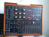
(click on picture to enlarge)
-
:thumbsup:
-
Don't worry, nothing dangerous will happen.
Just imagine that you've soldered a big el-cap into the box which will slowly ramp-down the voltage when you turn off the sammichSID, so that PIC and SIDs are sent into deep-sleep softly. :sleep:
Best Regards, Thorsten.
-
No, there is no real advantage if you would use a GLCD with 128x64 resolution.
MIOS32 will just show the content with 6x8 pixel characters, which means that up to 21x4 characters could be displayed - but the firmware doesn't use of the additonal two lines. They will appear empty, and this looks ugly!
That's a general rule for any MIDIbox: if a firmware doesn't explicitly support graphical images or more than the standard 2 character lines, the GLCDs are just handled as a dumb output device which emulates a CLCD, and all unused lines are blank.
SCS: most parameters are accessible, which means in other words: I believe that all parameters can be edited, but if I missed one, just let me know and I will add it.
Mostly I use the Lemur based solution, therefore only for this one I can guarantee completeness.
Actually I only use the SCS for quick changes without turning on the iPad, e.g. if I want to check if a CV channel if it's working.
Compared to Lemur the handling is very cumbersome...
Best Regards, Thorsten.

BLM16X4.ngc - Invalid flag in EVENT_LED_MATRIX
in Testing/Troubleshooting
Posted
Hi,
you are right, this is a bug in the parser.
Here a link to the updated firmware: http://www.ucapps.de/mios32/midibox_ng_v1_032_post1.zip
Best Regards, Thorsten.