Lorcan
-
Posts
83 -
Joined
-
Last visited
Content Type
Profiles
Forums
Blogs
Gallery
Everything posted by Lorcan
-
I wanna be a happy fella if it's still time. I only need one board, the gm5 chip I already have. Thanks ! I got the pcb from another member who had a spare so I won't be needing it anymore. Regards, Lorcan
-
Very impressive ! The pcb layout looks very tidy, even in prototype form. It's great that you still invest your time in this project. Apart from Tango (very expensive) and Euphonix Studio (not too sturdy looking and Mac only) controllers, there hasn't been much innovation on the commercial side, so I guess this is even a bigger incentive to build one yourself. Out of curiosity, may I ask what type of algorithm you use for tracking and control of the fader ? I guess you use of some kind of regularization of the control curve, or movement / speed prediction, so the motor speed is as smooth as possible. I know very little about automation theory (more about dsp) but as I said, I'm curious Cheers, Lorcan
-
A mon avis tu as un simplement conflit entre les entrées des encodeurs et des assignations de boutons. Il faut que tu regardes la valeur du SR et du pin pour les encodeurs dans le setup qui marche, tu la reportes dans ton fichier setup édité, puis tu vas dans lc_io_table.inc et pour les registres SR correspondants, tu mets 'ID_IGNORE' pour ceux-là dans la colonne 'button'. Fais pareil pour les ledrings/vu et ça roule Ce serait dommage de s'arrêter là , une midibox sans encodeurs ca ne sert pas à grand chose ... Ceci dit ça fait du bien de regarder à nouveau la tête reposée quand on bloque
-
Au vu de ta question 'est-ce que la config de tes encoder est correct' j'ai la vague impression que tu as raté quelques trucs ... enfin Bon qu'on soit d'accord, le make est un fichier qui réunit l'ensemble des fichiers sources (assembleur) à compiler en code binaire exécutable par ton PIC. Le make génère deux .hex (fichier binaire exe), chacun pour une config différente, une de 'référence', une autre pour le setup de Thorsten. Tu dois charger dans MIOS le .hex compilé qui correspond à ta config (fichier setup ...), que tu édites via le fichier source Il FAUT que les sorties matérielles auxquelles tu as connecté tes encodeurs, leds, etc correspondent à la définition dans le setup, sinon c'est le bronx, voire un gros plat de spaghetti trop cuits. En effet, rien ne dit que tu as connecté ton biniou comme Thorsten, moi ou un autre, c'est pour ça que c'est configurable d'ailleurs, afin de permettre une certaine souplesse au niveau du cablage et des fonctionnalités offertes Donc étape suivante: identifier les correspondances des E/S software<->hardware dans le fichier source Et si tes encodeurs marchent dans une config, laisse la définition des E/S des encodeurs comme ça et édite ce qui ne marche pas, pas à pas.
-
Il y a forcément un problème qq part que tu as raté, ça marche pour tout le monde ici ... Est-ce que tes vu/rings s'allument alternativement quand tu tournes l'encodeur ? Il y a un multiplexage donc tu verras plusieurs leds à la fois ... Ensuite si tu es sur que les branchements sont à 100% corrects, ça vient forcément de la config soft Il faut que les I/O hardware correspondent aux I/O en soft, et crois-moi c'est facile de se gourer Mettre en mode Mackie Control (universel, dont Cubase), pas LC (pour Logic seulement) #define LC_EMULATION_ID 0x14 ; use 0x10 for Logic Control, 0x14 for Mackie Control Activer le support soft #define LEDRINGS_ENABLED 1 ; if 1, ledrings are enabled #define METERS_ENABLED 1 ; if 1, meters are enabled Attention à ce que tu n'aies pas activé ça par hasard ;; NOTE: it's possible to display the meter values with the LEDrings by using ID_MBLC_*LEDMETER* buttons! ;; this feature saves you from adding additional LEDs to your MIDIbox Les connections des ledrings et vumètre multiplexés #define LEDRINGS_SR_CATHODES 8 ; shift register with cathodes of the 8 LED rings #define METERS_SR_CATHODES 9 ; shift register with cathodes of the 8 meters #define LEDRINGS_METERS_SR_ANODES_1 10 ; first shift register with anodes of the 8 LED rings (and 8 meters) #define LEDRINGS_METERS_SR_ANODES_2 11 ; second shift register with anodes of the 8 LED rings (and 8 meters) Les connections du display time codfe avec les afficheurs 7 segments #define LEDDIGITS_ENABLED 1 ; if 1, leddigits are enabled #define LEDDIGITS_SR_SEGMENTS_1 12 ; shift register which drives the segments of digit 7-0 (right side) #define LEDDIGITS_SR_SELECT_1 13 ; shift register which selects the digits 7-0 #define LEDDIGITS_SR_SEGMENTS_2 14 ; shift register which drives the segments of digit 15-8 (left side) #define LEDDIGITS_SR_SELECT_2 15 ; shift register which selects the digits 15-8
-
On sait bien qu'on est pas responsables, pas la peine de préciser :frantics: En ce qui concerne ton problème, je vois deux pistes: - utiliser les applis de debug pour vérifier que les connections led/DOut sont bonnes et correctement mappées (moi j'ai utilisé celle qui permet de scanner les sorties Dout avec un encodeur, voir dans le repository) - vérifier que ton setup soft des connections correspond bien aux mapping des E/S hardware dans le fichier setup et dans lc_io_table.inc Si tu as édité des trucs à la main peut-être que repartir d'une base vierge serait une bonne idée ... En tous ca à vue de nez je dirais que c'est vraisemblablement soit un problème de config des E/S soit un mauvais routing des leds De toute façon comme avec la plupart de ces choses là il faut procéder par étapes, du plus simple au plus compliqué, en éliminant les inconnues au fur et à mesure
-
Bizarre ton problème ... tu as vérifié que les jogs/encodeurs envoient du MIDI déjà ? Pour mettre l'interface midi hors cause, tu peux configurer l'appli pour allumer des leds de ta midibox lors des E/S midi, c'est dans le fichier de config
-
Hi, your best bet would be to build the core and connect one lcd to check for alignment. The idea is to align the channel name (7chars +1 space i think) with the faders. Of course you can make assumptions based on LCD char size etc but I found it's easier to test using the real thing. My LCDs had big margins on the side so that accounts for the big separation, but of course YMMV here. You could always try to put one LCD PCB on top of eachother, but they wouldn't be perfectly aligned vertically ... Here's how it looks on mine http://www.lorcan.me/projects/daw-controller/
-
Hurray it works :sorcerer: Thanks for the quick fix
-
I'm using the default, and there's no J8 on my board (v1.1)
-
They were lost in the process of the forum upgrade it seems. Also there was a minor error that I corrected afterwards on the pcb, so I need to correct the layouts first. I'll put them up at my site and give you the link here when it's done Edit: the schematics are still there in the posts above. I'll still post the corrected version
-
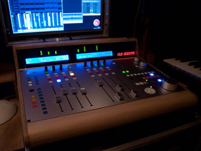
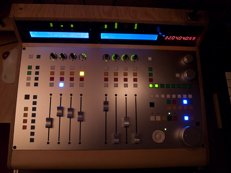
Here are of a few pictures of my LC clone which I finally found time to finish and debug One encoder cap got lost in the process .. Buttons colors follow some sort of rule so I can reach them without having to look at a small unreadable legend The case is made of 10mm plywood and I used plexiglass to cover the LCD display, Timecode display and meters. It also features a lamp and a monitor control (volume and mute). It feels great to use, and I'm really glad I didn't go the easy way and buy the Mackie which seems quite pale in comparison ;) This is one sturdy beast, it's built to last More details on the construction I already posted feel free to ask any questions if you're intersted

-
they do, in fact I've found it's the only way to use the GM5 atm under 7/64, at least on my system
-
Where did you find x64 version of 1.06 driver ? It's not on the GM5 page ...
-
Update: it's not seen by MidiOx or MIOS Studio either The strange thing is that under Windows 7 it seems that there is no Midi Properties to be found anywhere in the Control Panel
-
Thanks for the update, unfortunately the GM5 is not recognized with this driver (as was 1.07) under Win 7 x64, so I have to use the legacy driver, and can't benefit the tighter timing this driver offers. More specifically, the driver does get installed but applications don't see the ports (tried with Reaper x64 and Cubase 32), which is quite strange ... Do you think you could report this to ploytec once others have confirmed the issue, or should I report it myself directly ? Thanks, Lorcan
-
I removed my name from the list, as I ended up making my own. I hope that's ok
-
Hi, I'm using the GM5 in standard midibox.org configuration. With the legacy driver of my OS (Windows 7 64bits), the ports are listed, but when I use ploytec's 1.07 x64 driver, the driver installs correctly but the corresponding MIDI port names are not listed. The GM5 pages states that one should revert to 1.06 in this case, but there is only a 32bit version available. Any ideas please ? Thanks
-
I can't answer about the Core32 part, but there's no reason why you couldn't build your stripped-down LC as you describe. Just leave out some DIN's and DOUT's if you don't need them, and clamp unused inputs to ground. If you're using Cubase or any other sequencer you'll find the other buttons very useful though, so I'd recommend building the full monty. The biggest difference with the BCF is the LCD ! I had a BCF which was frankly quite a pain to use because of the lack thereof, but now I find it a breeze to edit. The eq, fx, etc are very quick to dial, and you can assign your own favorites to the Fcn buttons. Make sure you use 2 2x40 lcds to see everything, and align the faders with the channel names. As for the noise, I use Alps faders and the noise is ok. You're always going to get some noise anyway, it depends on your case too. If you make it rigid and damp fader vibrations sound won't resonate and the noise will basically be the noise level of the fader motors which is low. Precision is great here, no jitter either, Thorsten really did a great job. Make sure your build is clean and you use a good psu though, as this can influence results. And make sure you don't have any ground loops as this will induce electrical noise and could cause jitter and other annoying phenomenons.
-
Great ! And again, thanks a lot for offering this service to us 8)
-
The PSU is quite a standard design, but it works well If I were you maybe I'd change the orientation of the heatsink though, with retrospect I think the reg and the capacitor is squeezed in between the trafo and the heatsink which isn't great in terms of air flow. It would be better if there was some free space around the reg and the big cap to let them breathe a little more.
-
Wow, the custom pcb must have cost a little fortune, no ?
-
Hi, I redid the schemos from sratch, see this post http://www.midibox.org/forum/index.php/topic,13602.msg117036.html#msg117036 I'll upload the rest soon
-
You might find you'll have to readjust your design once you have the parts at hand. Keep in mind for example the lcd spreads farther than the visible window