emerson
-
Posts
30 -
Joined
-
Last visited
-
Days Won
3
emerson's Achievements
MIDIbox Newbie (1/4)
3
Reputation
-
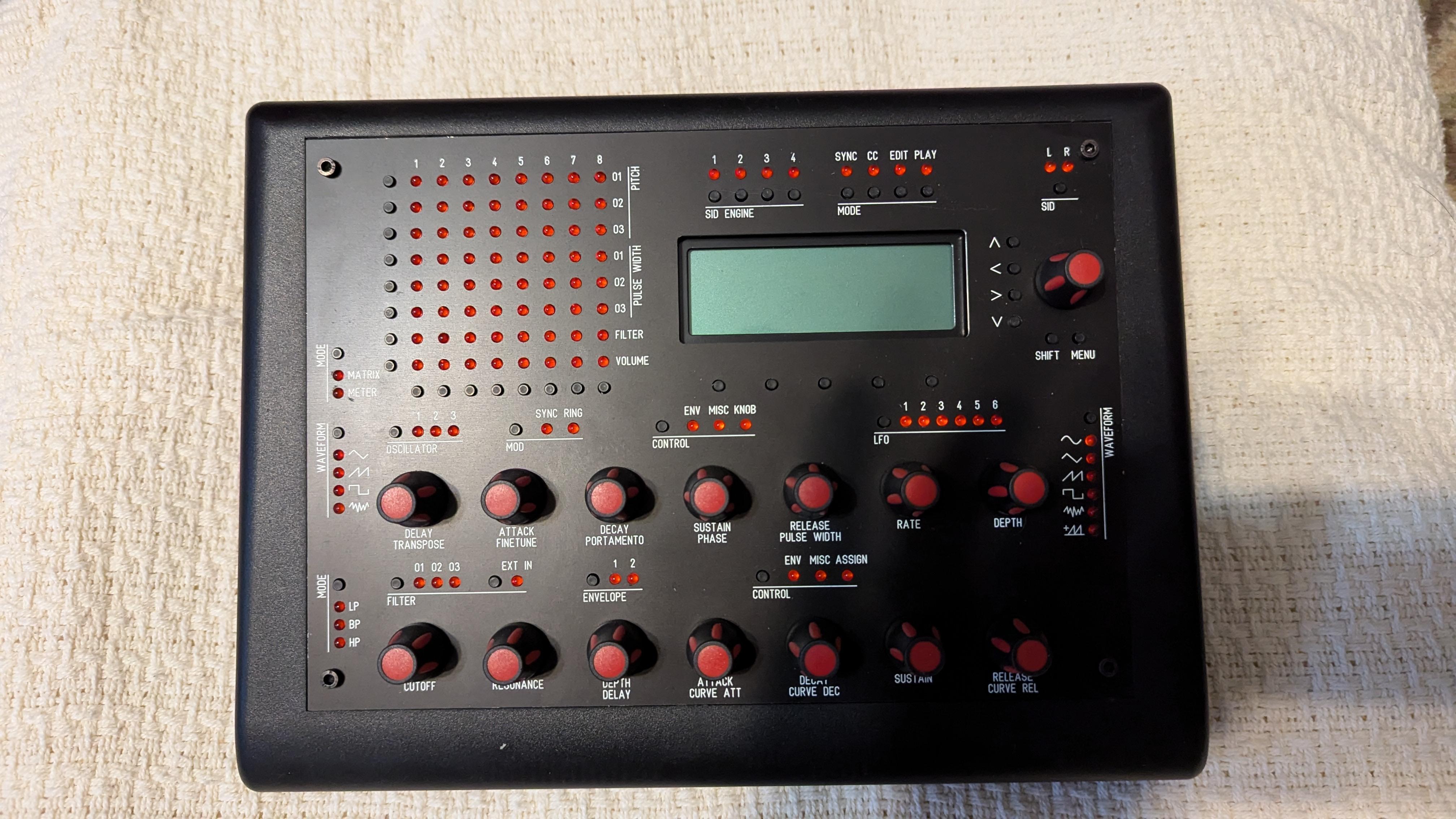
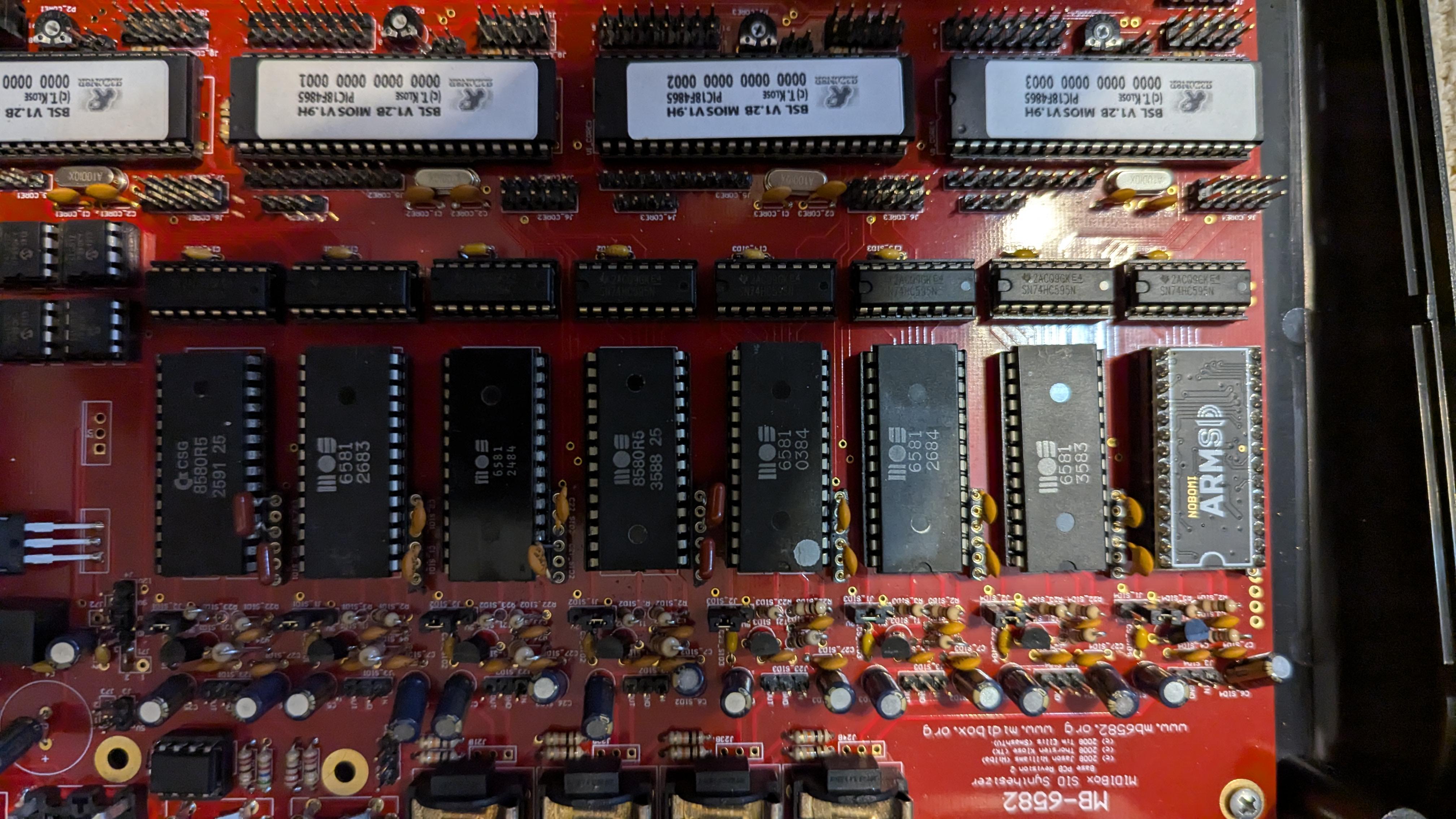
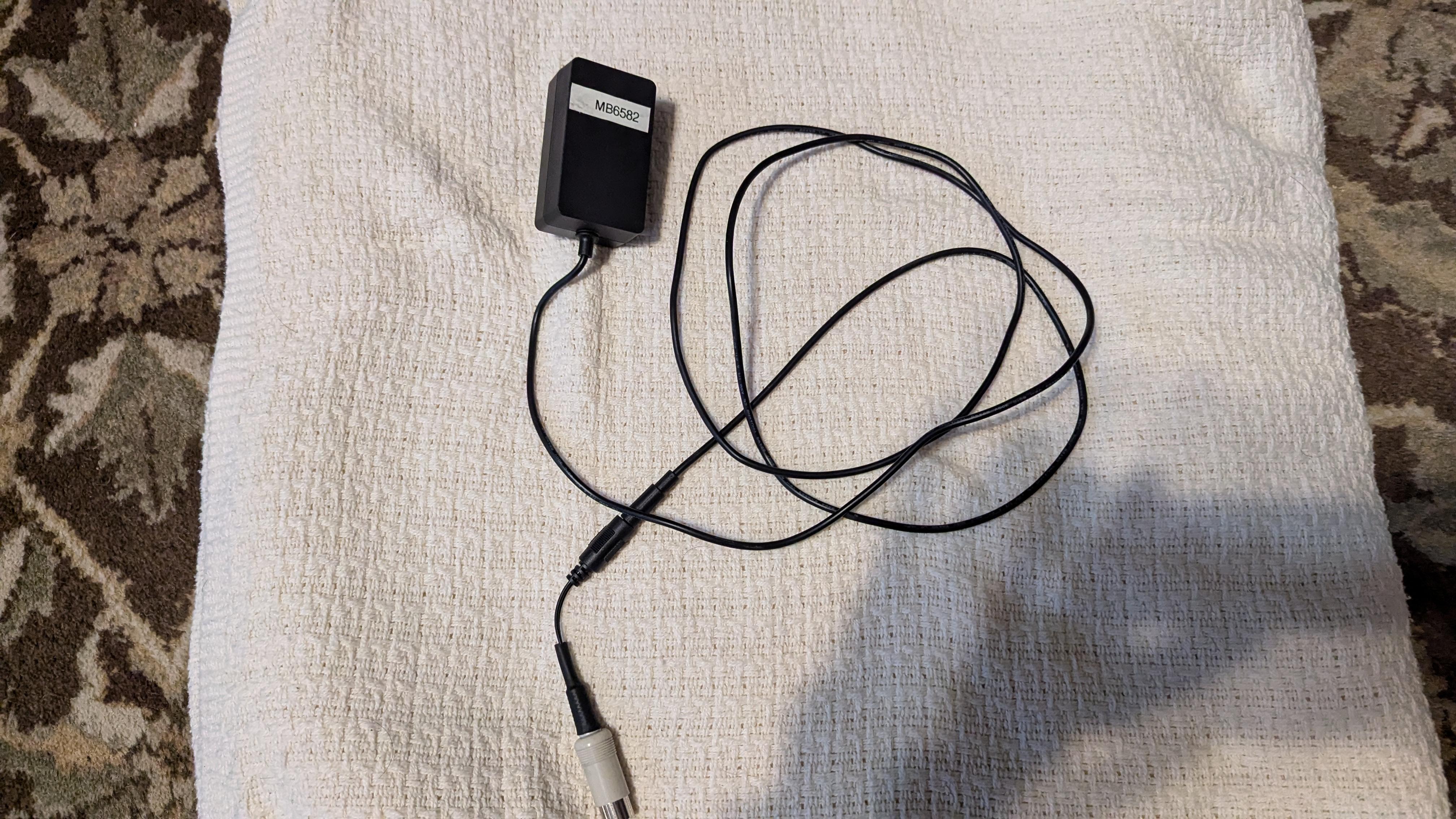
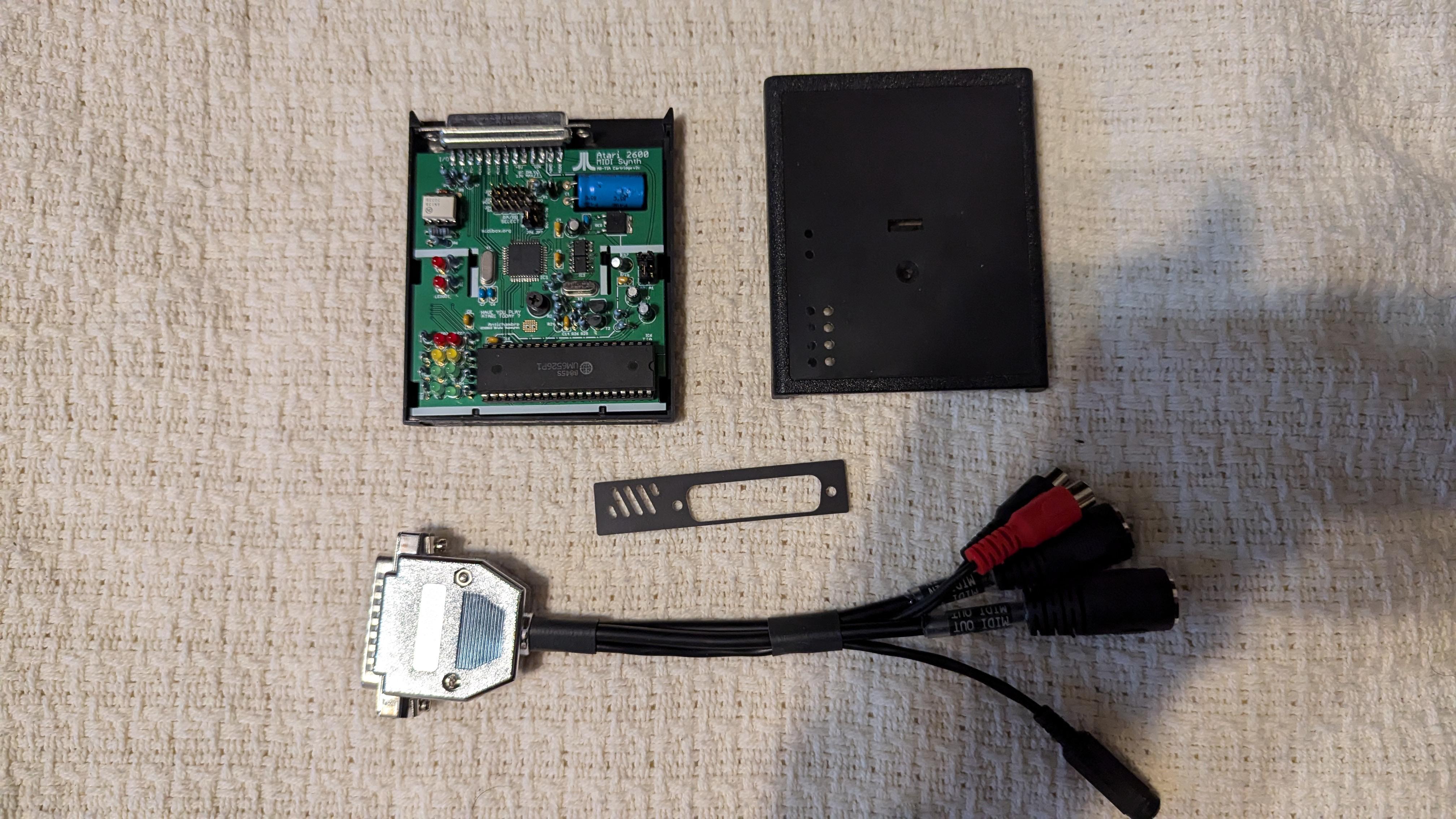
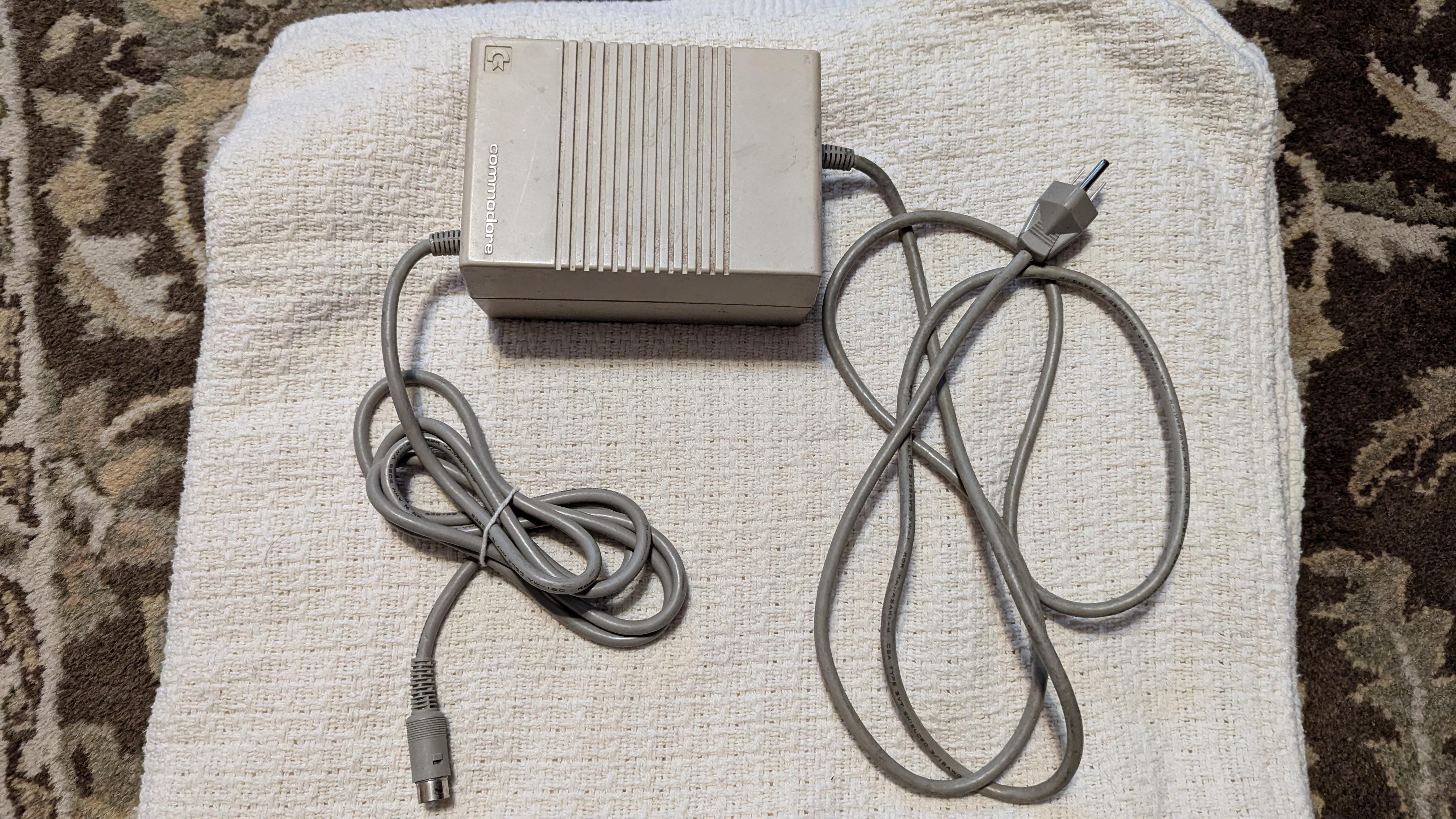
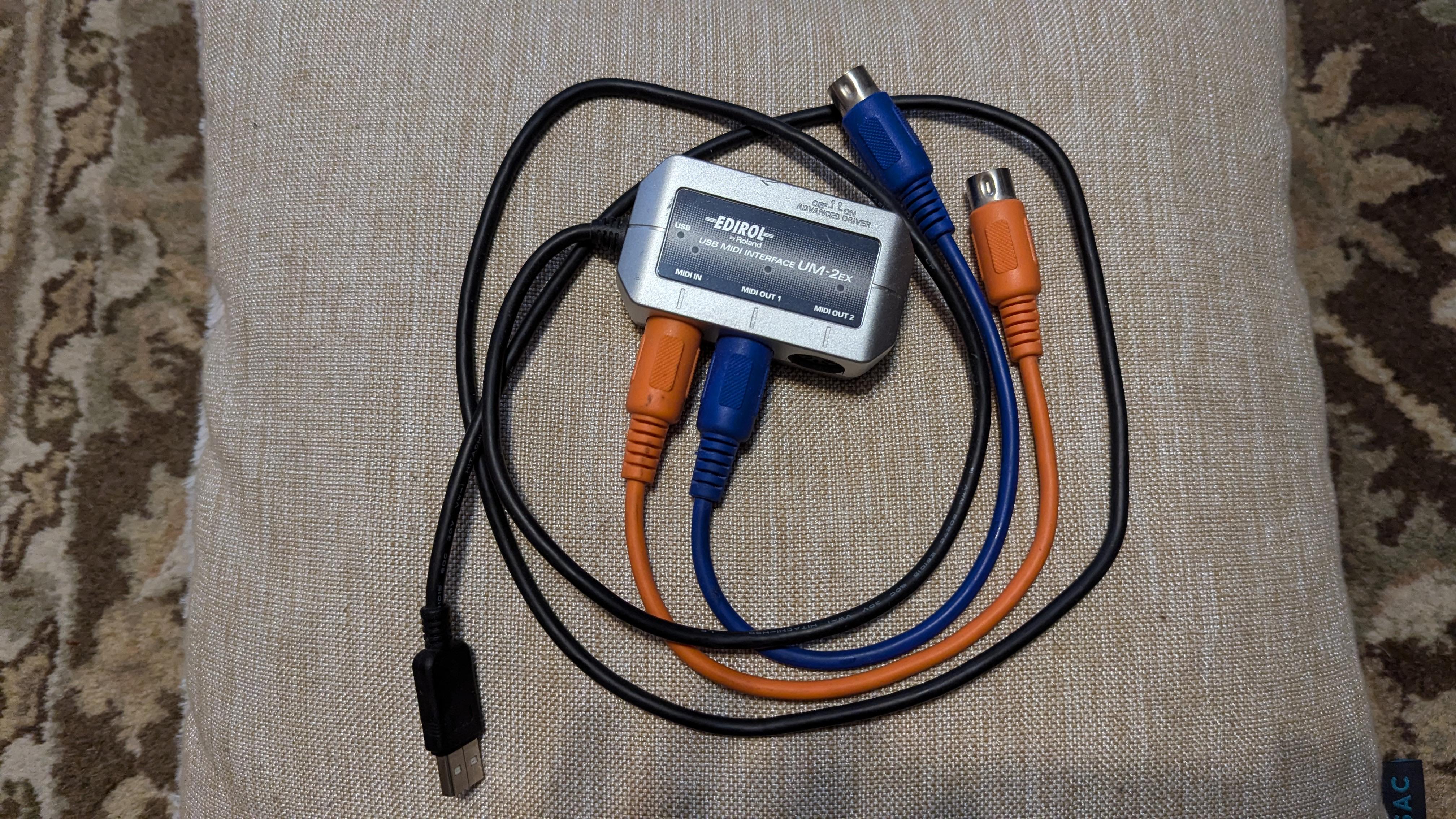
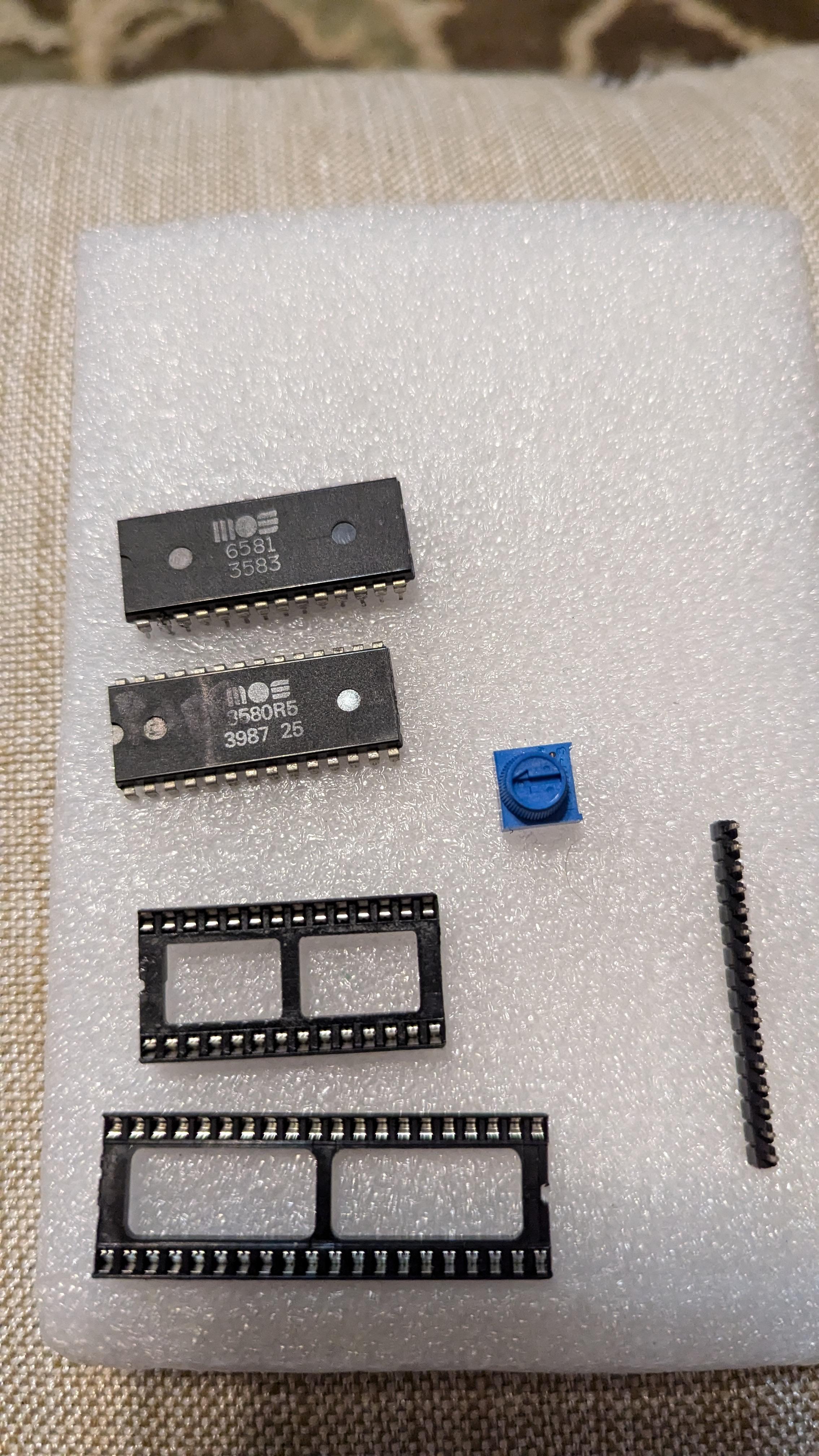
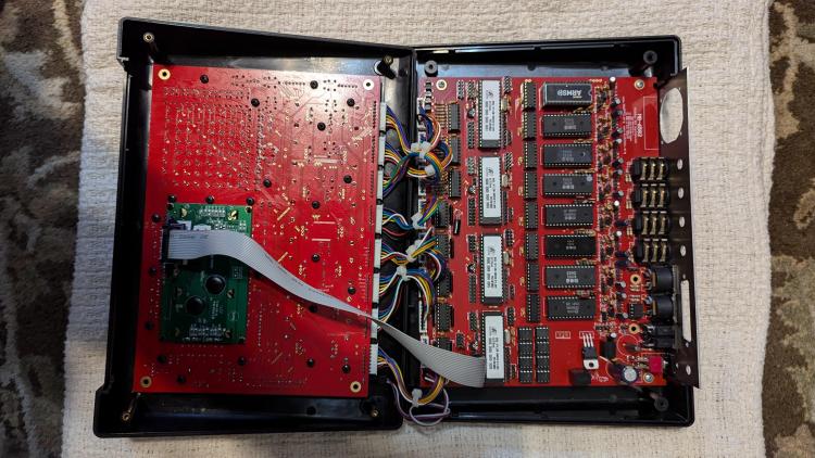
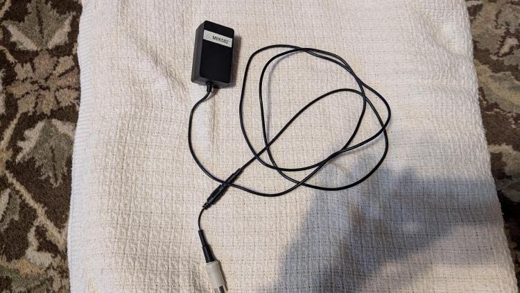
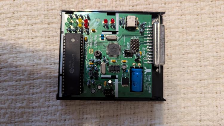
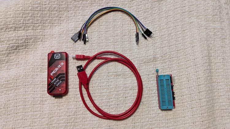
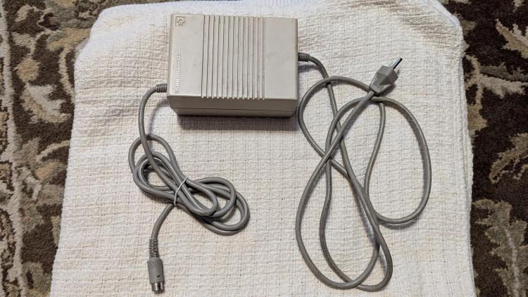
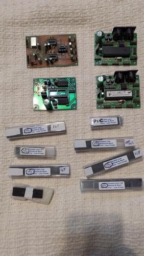
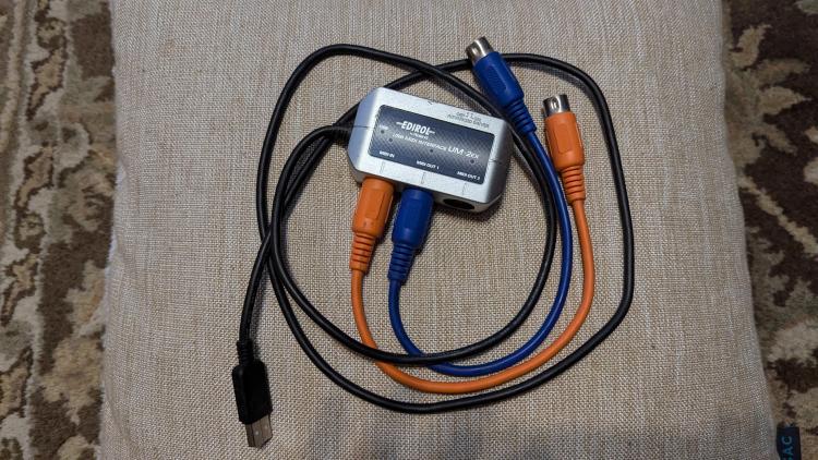
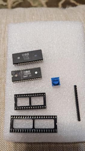
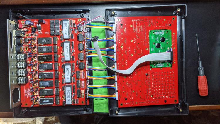
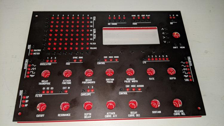
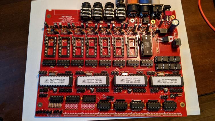
 First, let me get this out of the way: I am not interested in splitting this up; I'm mostly only interested in shipping to the US though that's not a complete dealbreaker, given the right person. I'm downsizing, can't really tinker with little fiddly electronic-y things any more, and so a bunch of these old MIDIBox projects that I nearly finished need to go. In this collection: -- Nearly-working MB-6582. This is a complete unit, panels, knobs, case, display, etc, containing eight SIDs, seven actual MOS of various flavors, one ARMSID. It is in principle complete, but it needs debugging. It powers up, the matrix lights flicker in an interesting pattern, the display fills up, and then nothing else. It's almost working. Someone wiser in the ways of these things could pull it across the finish line pretty easily, I think. Was modded to take a simple wallwart power supply, which is included. I believe all of the SIDs work but cannot completely guarantee that. -- Nearly-working MIDIBox TIA. Also a complete unit, populated board, chip, Atari cartridge shell to house it, cables, almost ready to go. This one again, nearly works but doesn't finish initializing. Debugging in these forums a couple years ago lead to the hypothesis that the RAM chips are sketchy or poorly-soldered. My surface-mount soldering skills are bad, so this is certainly possible. It also just needs a little debugging and some work by someone better at this than me. I do not have the power supply to drive this but I believe it takes a very standard one. -- Boards and (most?) parts for a second MB-6582. I'm not quite sure how I got here, but I have all or nearly all of the innards (apart from SIDs) for a second MB-6582, including circuit boards, LCD display, and components. No knobs, case, panels. I can take a more exact inventory of this if someone's interested. -- C64 power supply, believed working. (NB: this is NOT for the near-finished MB-6582, but for the hypothetical one still to be built. The complete one is modded to use a wallwart.) -- A few MIDIBox modules/boards, working -- 2xCore, 1xSID (no SID), 1xOPL (not fully tested ever). -- About a dozen loose PICs of varying types. -- PicKit 3 -- Edirol USB MIDI adapter + 2 MIDI cables -- Two extra MOS SID chips, PROBABLY BAD. I don't remember for sure but the only reason I would have set these aside in the first place and bought the ARMSID is if I couldn't get these to work. Maybe someone else would have better luck with them. -- Some ribbon cable and ends for connecting the smaller boards; extra components of various types. I can inventory these if someone's interested but there's no real treasure here, just the rest of my bits drawer. I can take more pictures of this stuff as needed. Looking around, I see people selling complete sometimes-flaky 6582s on Reverb for $900-ish. I'm thinking in aggregate I'd like to start at about $1500 + shipping for this whole collection. Like I mention at the top, I am not interested in splitting this up into little dribs and drabs and getting stuck holding the wee bits at the end; I'm wanting someone who's excited about jumping into this universe to take the whole thing. I'm in the US and mostly interested in shipping only to the US, but convince me and I might risk it. A little sad to see this stuff go, but it's been sitting idle for years and I'm not going to be able to use or work on it any further, so hopefully there's someone out there who's perfect for this collection. Following this thread, but also DM me if you are interested. PXL_20241102_214946707.mp4


-
Almost there (stay on target).
-
Following the MB6582 Control Surface Construction Guide, I'm nearly to the point of soldering the pins for the encoders. The guide then offers the advice "Test LEDs now if you wish" and references J2 (the one near the power supply on the main PCB, I guess?) but I'm not sure what specific action is meant by that. How would this notional LED test work? Thanks in advance. (Edit: for posterity, I now realize it's talking specifically about the optional LEDs for illuminated knobs.)
-
Phase II proceeds smoothly....
-
I got hold of one of those aluminum-case probably-bootleg sammichFM and have been playing with it for a couple weeks. It wasn't in the best shape and I've fixed up a couple small issues already. I noticed a weird behavior that I'm sure is totally obvious to someone smarter than me: notes will crackle and be distorted a bit out one stereo channel, then out the other, in groups of three. That is, if I play three notes in a row, they'll all be distorted on the left, then the next three I play will be distorted on the right. Also, if I play a three-note chord over and over, that counts as the three notes, and the distortion will jump from channel to channel with each chord. My suspicions contain thoughts about polyphony and voices per channel and so forth, but I'm already in over my head. I imagine one of the OPL DACs and/or one of the op-amps is needing to be replaced but I have no idea how to track that down without just starting to desolder SMDs off of the board which ouch. Anyone have any guidance about how next to debug this? I've attached an MP3 of playing notes and chords; the stereo distortion-swapping effect is probably best heard through headphones. Thanks! three note distortion.mp3
-
Well, I let it sit for a couple weeks and came back to it yesterday. I've reflowed every solder connection (apart from the PIC itself), tested continuity all over the place, reflashed the TIA app a couple times, replaced the banksticks, and tried both MIOS Studio and the Max Manager to contact it while it's doing whatever it's doing. When powered up, it blinks MIDI In and Out, then MIDI In comes on and the volume LEDs do the pattern that means bankstick init. And there it stays, no matter how long I wait. I've started to suspect that maybe the PIC itself is bad, or has a badly soldered pin maybe. I got it preinstalled on the board from Modular Addict, so I haven't wanted to dig in there myself, especially since my SMD soldering skills are not great. There's nothing obviously visibly wrong with its pins, so I feel like I'm starting to grasp at straws. Anyone have thoughts on further debugging what the PIC thinks it's doing while it gets stuck in the "initialize bankstick" phase?
-
Second status report: of the nine SIDs I'd salvaged from C64s through the years, seven boot up and make noise, two 8580s and five 6581s. I guess I'll need to get a SwinSID or something to fill this out, but that's actually a better ratio than I expected, so again I am delighted.
-
I intend to build the control surface, too, and have gathered the case and most of the rest of the needed stuff, but this has been a slow burner so no telling when it'll be done.
-
Very pleased to report that my 6582 has made its first noise -- notes played on the MIOS Studio keyboard trigger the one (so far) 8580 to play that lovely reedy default patch. This is delightful. Thanks for all your help so far, all y'all.
-
Aha that's good info. I let it run for a while, like 20min, and it kept going, so I'm having the hypothesis that my banksticks are at fault. Knowing it's supposed to do that LED pattern, though, is heartening, we're getting somewhere at all finally. I tried that other firmware without any change. So to be clear, the one issue is that with one MIDI interface, it leaves the MIDI In LED on constantly. With another, it doesn't. Neither seem to respond to note-on or the like. I'll also try the Max manager. So far I've tried just the virtual keyboard that's part of MIOS Studio, without luck -- no MIDI LEDs lighting, no notes out, so I think it's just stuck in that initialize state and not fully starting. (Edit: Yeah the Max manager won't even connect.) So, later I'm going to desolder the banksticks and try re-adding a fresh pair I have sitting around. I remember I had trouble with the SMD soldering on this pair so I might have damaged them or have shorts hidden underneath them or something. (Edit: fresh pair of banksticks had no effect, still stuck in the bankstick init LED loop. Gonna keep looking around there. Early testing shows that exactly the correct pins of the banksticks are connected to ground, still gonna work on testing others' connectivity to the right places.)
-
This is the third re-edit of this post because the bootloader and MIOS and setup_tia_cartridge.hex have *finally* all been successfully loaded (I reflowed a couple sketchy-looking solder joints, reseated the optocoupler a couple times, suddenly all is well with MIOS Studio). So we're back to the initial problem, though with a new twist. The MIDI In LED is staying on constantly, and now the "level" LEDs are lighting up in pairs, descending from the red ones to the bottom green ones (video below). Further edit: Actually hooked the box's audio up to see whether it's working despite no MIDI indicators. It's not, but it is creating a -hellacious- burst of Atari-noise at the end of every LED cycle. Also, weirdly, out here in the studio room, the MIDI In LED isn't lit. Forum server didn't like the size of the photos, so: https://hayseed.net/~emerson/TIA/ ...has pretty good pix of the front and back, as well as a short video of the new LED behavior with the sound burst audible, though turned way down.
-
OK good, I'll leave it alone. After a couple of false starts, I got my PICkit clone's six pins connected to the jumpers as per the illustration. I fired up MPLAB X IPE, selected device PIC18F4685, told it to power the PIC via the PICkit, connected successfully to the PIC, and selected bootloader_v1_2b_pic18f4685.hex from the mios_v19_h.zip archive from ucapps.de/mios_download.html. It programmed just fine, said it succeeded with no errors. My intent then was to get it talking to MIOS Studio to verify it was working, then upload MIOS itself and then finally the TIA app. But now, it's not even spitting out the little sysex handshake blob that the bootloader normally sends at power-up time, and that it had been doing up until I started messing with MPLAB. "Query" doesn't work at all, which I guess is to be expected. Oh yes, I'd forgotten the jumper at first but did catch that error pretty early and put it back into the right place, with no luck. I also did a second pass of connecting it to the PICkit, running MPLAB, and programming the bootloader hex file, which also alleged to complete successfully. I'm gonna sleep on this and see if I find success tomorrow. Thanks for walking through this with me so far.
-
The green and white ones are correct, both pairs, and my meter tells me that the DIN pins and the DB25 pins for those are connected as you say. Weirdly, DIN pin2 isn't grounded, even though the third wire from the MIDI Out cable goes to that pin. I guess it didn't connect well when they made it, and I'm gonna have to take the connector apart more to debug that. Hmm I used my PICkit clone to reprogram the bootloader into the PIC, and MPLAB reported success. Now, though, when I put power to it while connected to MIOS Studio, it doesn't even give off the initial "f0 00 00 7e 40 00 01 f7" that it did previously. I re-tried flashing the bootloader with MPLAB, and again it reported success, so the PIC is alive, at least, just not... doing anything. That doesn't work, and didn't work previously before I started tinkering with MPLAB -- it just gave the normal "No response from MIOS8 or MIOS32 core!" etc etc error.
-
Am I right in seeing that the center pin of the MIDI Out DIN should be attached to pin 15 / ground of the DB25? That one is not, I'll look to fix it. The other four from the two MIDI DINs are correctly connected (ie, MIDI In seems to be hooked up correctly, unless it relies on the pin 15 / ground from the MIDI Out DIN). (Edit: Or is this the thing I vaguely remember where you ground the MIDI cable shield but don't attach it to one of the pins?) MIDI In isn't working, and I don't have a PIC burner for surface-mount PICs, so... not yet. Am I correct in thinking that the MIDI light staying on is possibly destructive and I shouldn't keep it powered up that way? Thanks!
-
I've made it to the "power it up and see" phase of building the cartridge TIA box. When I do apply power, the LEDs for MIDI In and Out blink briefly, which feels like a booting-up indicator, and then the MIDI In light turns on and stays on. That seems like a bad symptom so I pull power immediately. I've tried reflowing some of the solder joints around the optocoupler's cluster of components and the DIN pins for MI+ MI-, also looking for solder bridges etc, but no luck so far. FWIW, MIDI Out is working as expected -- when I power it up connected to MIOS Studio, it sends the "f0 00 00 7e 40 00 01 f7" as expected. It's just the MIDI input on the cartridge that seems bad. Any hints on where to look next for this? I'm bumping up against my late-beginner limits. Thanks in advance.