Wise
-
Posts
113 -
Joined
-
Last visited
Content Type
Profiles
Forums
Blogs
Gallery
Everything posted by Wise
-
I'm using SMD to save some PCB space.... sooo tight onthis PCB as you can see ;) For everyones pleasure, I can tell you that the transport module work (and at first try) !! DIN, DOUT and encs Q: How happy am I ? A: ;D ;D ;D ;D ;D ;D ;D ;D ;D ;D Now it's just to decide what colour on the leds I want and solder the rest of the buttons. Then fabricate all other PCB's. Dont going to use this faders in this project.But they feels quite Ok. Actualy I have not tested them at all, but it's a nice smooth travel. Now to bed and see if I can get some sleep... 8)
-
So... I finished the board today so I can test it. I just stuffed the components needed for first basic test, and some connection cables. Hard to solder those SM chips after 11h at work. :o ..... Tomorow I can run the first test, cross your fingers !
-
;)
-
You can buy those button from www.voti.nl , http://www.voti.nl/shop/catalog.html?M-SW-5-1. The plexirod I use is 8mm dia, drill a little hole in one end and put the buttonsteem in the hole with some epoxi. Then mount the LED tight to the button, done ;D Very easy, and it's easy to adapt to other kind of buttons.
-
Hi! Sorry for my late update. But I have not got the time to finish the board for test. Hopefully (again...) , I think I'll have the board ready for the first test on friday. So far (300 holes and 25 jumpers): .
-
First board etched : I'm realy satisfied with the result. The board is 100*180mm and is for the transport section of the controller. Close up: The shiftregisters for DIN and DOUT are SM. Some other components arrived. Enc's and long faders from VOTI, other from www.elfa.se (60mm ALPS fader and faderknob, thoose tactile rubberfeeling buttons with keycaps: Tomorow i'm going to drill the board and mount some components to se if I have connected everything right 8) Hopefully I'm coming back and report with a smile on my face tomorrow :) /Wise ps. I'l fix the pictures in the earlier posts soon. My ISP moved to another location... edit: fixed pictures
-
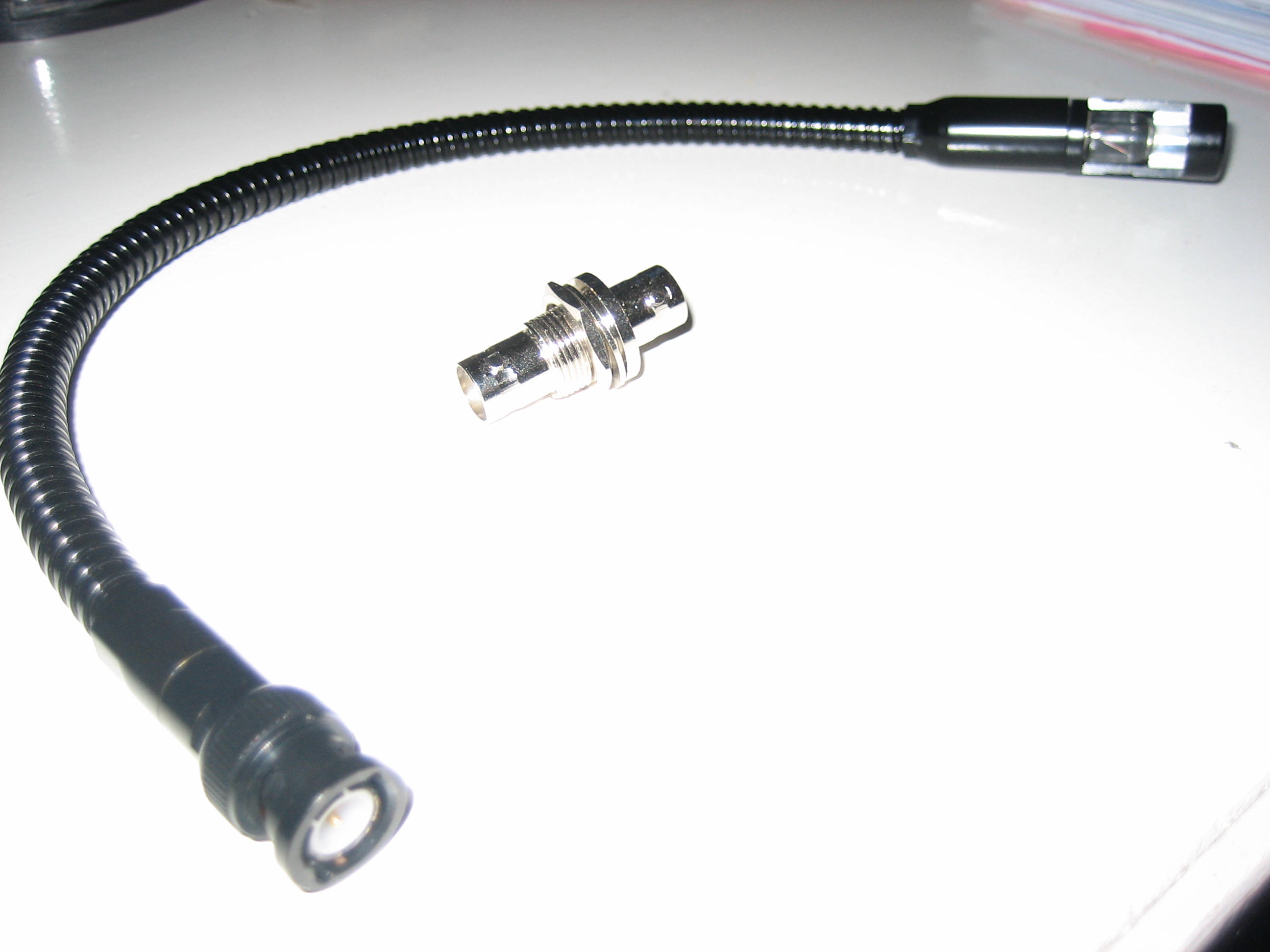
Short update... Bought a gooseneck ??? lamp and a frontpanel bnc connector for the project yesterday:

-
Thanks lordmortis Sure you can reuse my layout and boards, just tell me what you want. But have in mind that none of the pcb's, layout issues are tested IRL. I'm just in the design phase of this. Also have in mind that i have not programed anything yet, but maybe you can do that yourself. Oh, and, 1 CORE is capaple to handle two deck controlls(loop, FX, transport) (due to the 128 DIN limit). So if you are going to have 4 decks, you must have 2 cores.
-
Finaly i got some cash at my paypal account, so now i'm waiting for 40 encs 10 10k lin, 100mm slides (for future boxes) + some other stuff. SWEET :P Cool :) That sucks ! Maybe a grouporder someone ? edit: encs and slides from Voti...
-
Thanks Stryd :) Just to clarify, when I said "rubber" feeling for the square buttons i meant the tactile switching, NOT the cap ! I'm going to drill a hole in the black cap so the led will light up from there (it's not done in the picture). Maybe fill the "hole" with some clear plastic glue, epoxi or similar that the led can shine through. In the picture below you can see how the button is build This is the buttons: http://www.rjselectronics.com/cms/html/modules.php?set_albumName=album16&id=Fujisoku_TM_TR&op=modload&name=gallery&file=index&include=view_photo.php
-
Yepp, Frank "Wise" Sinatra totaly out of tune :P So, time for an update: PCB for LOOP the sections Front graphics The square buttons has "rubber" feeling. I'm also going to drill a hole in the keycap for the led. Allso you can see the connections to the left and right, thats where i'm going to chain the other pcb modules (fx, transport etc). I know, many airwires... But remember it's 4 Shiftregisters, 16 buttons, 16 LED's and ca 40 resistors at that card ;) Thats all for now Over and out /wise
-
The knobs look like thoose on this controller: http://www.midibox.org/forum/index.php?topic=2608.0 So cool 8) /wise
-
What do you mean that T3 doesen´t provide functionality for multiple transports ??? ??? Ass I can se you can assign a MIDI command (or hotkey) to whatever deck you want (A,B,C,D, Focus). No worry, I'll do it MY way :) But yet a good opinion 1. I sertenly have the space since I'm going to use the case that i already build for my discontinued T2 CS. 2. Money..just have to work some more ;) 3. Time is money.... so it's in comflict with nr 2. Conclusion: I'll have to be more effective in my work with the controller and take a talk to my boss ;)
-
Hi, ok. You define the activate button in the line: const deckA_wind_button = 0 ; Change to your pin number for your wind_activate button see: http://www.midibox.org/dokuwiki/doku.php?id=din_dout_pintable&DokuWiki=8f0d62891bc27340cb5fa485f867c297 (shift register vs. pin number You are right on the pins for the encoder, the encoder i connected to pin 2 and 3 (ox02 and 0x03), but I can't understand how you saw that out of that code :P , well... You define your encs in mios_tables.inc. The code as it is right now asumes that that the "wind encoder" is encoder number 0. Also the code sends events if you push the activate button and turn any other encoder, it's not finished... So you maybe want to change if (deckA_wind_active == 1) to if (deckA_wind_active == 1 and encoder == 0) then it just send data when activate button is pressed and encoder 0 is turned. Then sends 64 when you release the activate button.. Hope you understand my poor explanations and english. Let me know it you get this running. regards /wise
-
True, but I like to have some room to so i don't accidentaly touch or push anything. But I'll see if i can cut some mm's in the mixer section. To expensive, to large panel and I don't see the point of having four dedicated deck controllers. Most time you are just using 2 decks, then its handy to have them accessible without switching. And when I want deck 3 or 4, it's simple to switch to these like you would. And I think this duplication minimizes the risk for controlling the "wrong" deck. Oh, didn't do my reserch so well i see...But...They will stay there. I'm thinking that i can send a command at first press that sets the EQ to -100%, then at next press resets or set the EQ to the value before first press. Something like that. Thanks for the input ! :) /Wise
-
Working with the frontpanel layout, so far: Larger : http://www.gavle.to/~wise/MIDIBOX/T3_a1.gif Someone maybe remember that i worked on a traktor 2 controller for some time ago, true. Well, that one was throwed in the bin when t3 came out... You see the similarities from the old front in this new design. Pretty selfexplaining. Two set of deck controlls with FX, LOOP, EQ and Transport/tempo sections. Possibility to switch to another deck. All four decks have their own prelisten/gain/prefx and volume to be able to adjust these parameters without switching deck. Master FX, prefx and gain. X-fader and knobs for headphone volume/mix. The two dispays are thought to display deck parameters (hopefully traktor will have midi feedback in the future). In the upper left corner of the panel it's a chassimounted bnc for connection a snakelight ?? . Going to add a switch and a knob for controlling that to. Also I'm planing to add a headphone amp, so maybe there will be some knobs for that to somewhere. Impressions, comments and suggestions are welcome /Wise
-
As you use M64e and that application is in asm it's over my head, sorry. But the general idea is to check if the "activate button" is pressed when the encoder handeler is called. I'm looking in the m64e asm code right now and i see it's to complex for me right now... :-\ Maybe someone else with the proper asm knowledge can help you. Again, sorry :( /Wise
-
I will use insulated wires for the airwires, so i dont think the airwires will cause any problem. Maybe I route the wires so they dont cross over each other. The pcb cad program i use is the same as at my work, Easy-PC , http://www.numberone.com. So unfortanetly i can not save the pcb's as eagle files if someone should want them. But I'm more than happy to share gerber, pdf, dxf or whatever format someone can import to another program :) /Wise
-
So, here is the first pcb module: The front graphics: This is for controlling traktors FX section. Inc/dec buttons to select effect, 4 encoders and buttons for the effect parameters. The PCB: Single sided. Surface mounted shiftregisters and some resistors on the bottom layer. SIL headers on each side to chain the datalines to next module. Yiiii, so hard to route so many connections on just one layer !! So it's some jumpers on the board... Component test1: Component test with real components. Not much to say. Encoders from VOTI (ALPS on picture). Simple tactile buttons and LED's Component test2: Here you can se how i thought to do the lighted button. Similar as other here on the forum has done. 8mm plexi, cutted, drilled and glued.
-
So, here we go.. First a little picture of how i'm going to connect everything together: As you can see I will have a 2 core system as there are more than 128 DIN's. Power will be distrubuted to the cores and other modules through a common PSU. The boards A1,A2, .. , Ax, Bx are PCB's that will be mounted under the frontpanel. These pcbs have surface mount DIN and DOUT shiftregisters on them. All panel pcb's have power from the PSU to supply the registers. This way I will chain each pcbmodule to another and minimize the cables running to the bottom in the case. In the picture you can see this connection as purple lines. To minimize the risk for talkover between the datalines i thougt that putting a GND wire between each dataline (flatcable) could be a good solution. No need for AIN modules as I'm planing to use less then 8 potentiometers/faders. Just wire them direct to the core. So my first question: Anyone see any problem with the wiring of DIN/DOUT, possible ground/interference/dataloss/other problems with this method ? I will post some pcb designs soon so you can see what a typical pcbmodule can look like. Back to CAD :)
-
Hej! Lite sent relpy, men bättre sent än aldrig. Jag håller just nu på med min Traktor3 box. Har försökt fått till lite kod för wind funktion,inte riktigt optimalt än, men jag jobbar på det. Kanske inte vad du är ute efter exakt, men du kan alltid labba med alla exempelkodsnuttar som finns på ucapps.de. Hur långt har du kommit i planeringen/byggandet ? /Henrik
-
Have spoken to our Atmel sales representative and he sais that the M644 will be replaced by a m644p version, which will draw much less power. Therefore the note about new designs in the m644 datasheet. And Atmel has not released the datasheet for the p version on their website. /wise
-
Hello again I have looked into the code again and changed the "concept". Well, first of all i discovered that Traktor 3 seems to have a bug in the wind function. When setting up a deck wind cc, and send 0x40 (64) to traktor att that CC, the deck should stop winding but it dont. It's still slooooooowly winding in some direction. Traktor 2 dont do this.... So my solution: One "wind_activate" button to activate the encoder as "wind". When that button is pressed, the encoder sends CC of 0x01 or 0x7f depending on the direction. When releasing the activate button MIOS sends a "wind reset" CC to traktor. Traktor wind is setup as Deck wind, direct, rotary encoder (64). And the reset as Deck wind, reset, button. Setup the acceleration and sensetivity as you like and prefer. This way you can wind slowly in both directions and stop the wind when you release the button. Also you dont need to constantly spinning the encoder if you are winding long times as traktor wont stop winding untill you release the button. Good luck and let me know is any problem occurs and excuse me for my poor english explanations.... So, here is the code. You have to modify the constants in the program to match your activate button and encoder. Main.c: /* * MIOS SDCC Wrapper * * ========================================================================== * * Copyright (C) 2004 Thorsten Klose (tk@midibox.org) * * ========================================================================== * * This file is part of a MIOS application * * This application is free software; you can redistribute it and/or modify * it under the terms of the GNU General Public License as published by * the Free Software Foundation; either version 2 of the License, or * (at your option) any later version. * * This application is distributed in the hope that it will be useful, * but WITHOUT ANY WARRANTY; without even the implied warranty of * MERCHANTABILITY or FITNESS FOR A PARTICULAR PURPOSE. See the * GNU General Public License for more details. * * You should have received a copy of the GNU General Public License * along with This application; if not, write to the Free Software * Foundation, Inc., 59 Temple Place, Suite 330, Boston, MA 02111-1307 USA * * ========================================================================== */ #include "cmios.h" #include "pic18f452.h" unsigned char deckA_wind_active; unsigned char deckA_winded; const deckA_wind_button = 0 ; ///////////////////////////////////////////////////////////////////////////// // This function is called by MIOS after startup to initialize the // application ///////////////////////////////////////////////////////////////////////////// void Init(void) __wparam { MIOS_TIMER_Init(2,12500); // define number of shift registers MIOS_SRIO_NumberSet(4); MIOS_AIN_Muxed(); MIOS_AIN_NumberSet(4); MIOS_AIN_DeadbandSet(8); // update frequency of SRIO chain MIOS_SRIO_UpdateFrqSet(1); // ms } ///////////////////////////////////////////////////////////////////////////// // This function is called by MIOS in the mainloop when nothing else is to do ///////////////////////////////////////////////////////////////////////////// void Tick(void) __wparam { } ///////////////////////////////////////////////////////////////////////////// // This function is periodically called by MIOS. The frequency has to be // initialized with MIOS_Timer_Set ///////////////////////////////////////////////////////////////////////////// void Timer(void) __wparam { } ///////////////////////////////////////////////////////////////////////////// // This function is called by MIOS when the display content should be // initialized. Thats the case during startup and after a temporary message // has been printed on the screen ///////////////////////////////////////////////////////////////////////////// void DISPLAY_Init(void) __wparam { } ///////////////////////////////////////////////////////////////////////////// // This function is called in the mainloop when no temporary message is shown // on screen. Print the realtime messages here ///////////////////////////////////////////////////////////////////////////// void DISPLAY_Tick(void) __wparam { } ///////////////////////////////////////////////////////////////////////////// // This function is called by MIOS when a complete MIDI event has been received ///////////////////////////////////////////////////////////////////////////// void MPROC_NotifyReceivedEvnt(unsigned char evnt0, unsigned char evnt1, unsigned char evnt2) __wparam { // print received MIDI event MIOS_LCD_Clear(); MIOS_LCD_PrintCString("Received:"); MIOS_LCD_CursorSet(0x40); MIOS_LCD_PrintHex2(evnt0); MIOS_LCD_PrintHex2(evnt1); MIOS_LCD_PrintHex2(evnt2); } ///////////////////////////////////////////////////////////////////////////// // This function is called by MIOS when a MIDI event has been received // which has been specified in the MIOS_MPROC_EVENT_TABLE ///////////////////////////////////////////////////////////////////////////// void MPROC_NotifyFoundEvent(unsigned entry, unsigned char evnt0, unsigned char evnt1, unsigned char evnt2) __wparam { } ///////////////////////////////////////////////////////////////////////////// // This function is called by MIOS when a MIDI event has not been completly // received within 2 seconds ///////////////////////////////////////////////////////////////////////////// void MPROC_NotifyTimeout(void) __wparam { } ///////////////////////////////////////////////////////////////////////////// // This function is called by MIOS when a MIDI byte has been received ///////////////////////////////////////////////////////////////////////////// void MPROC_NotifyReceivedByte(unsigned char byte) __wparam { } ///////////////////////////////////////////////////////////////////////////// // This function is called by MIOS before the shift register are loaded ///////////////////////////////////////////////////////////////////////////// void SR_Service_Prepare(void) __wparam { } ///////////////////////////////////////////////////////////////////////////// // This function is called by MIOS after the shift register have been loaded ///////////////////////////////////////////////////////////////////////////// void SR_Service_Finish(void) __wparam { } ///////////////////////////////////////////////////////////////////////////// // This function is called by MIOS when an button has been toggled // pin_value is 1 when button released, and 0 when button pressed ///////////////////////////////////////////////////////////////////////////// void DIN_NotifyToggle(unsigned char pin, unsigned char pin_value) __wparam { if (pin == deckA_wind_button) { if (pin_value == 0 ) { deckA_wind_active = 1; } else if (pin_value == 1 ) { deckA_wind_active = 0; MIOS_MIDI_TxBufferPut(0xb0); MIOS_MIDI_TxBufferPut(0x00); MIOS_MIDI_TxBufferPut(0x40); } } } ///////////////////////////////////////////////////////////////////////////// // This function is called by MIOS when an encoder has been moved // incrementer is positive when encoder has been turned clockwise, else // it is negative ///////////////////////////////////////////////////////////////////////////// void ENC_NotifyChange(unsigned char encoder, char incrementer) __wparam { if (deckA_wind_active == 1) { MIOS_MIDI_TxBufferPut(0xb1); MIOS_MIDI_TxBufferPut(encoder); if (incrementer < 0) { MIOS_MIDI_TxBufferPut(0x7F); } else MIOS_MIDI_TxBufferPut(0x01); } } ///////////////////////////////////////////////////////////////////////////// // This function is called by MIOS when a pot has been moved ///////////////////////////////////////////////////////////////////////////// void AIN_NotifyChange(unsigned char pin, unsigned int pin_value) __wparam { MIOS_LCD_Clear(); MIOS_LCD_CursorSet(0x40); MIOS_LCD_PrintBCD4(pin); MIOS_LCD_PrintBCD4(pin_value); MIOS_LCD_PrintBCD4(MIOS_AIN_Pin7bitGet(pin)); MIOS_MIDI_TxBufferPut(0xb0); MIOS_MIDI_TxBufferPut(pin); MIOS_MIDI_TxBufferPut(MIOS_AIN_Pin7bitGet(pin)); } edit: pleeease pleese move this into the C section of the forum..
-
Yiii ! Doesen't sound so good for us :-\ Know why ?
-
Using ATMega8, 168, 32, 64 and 644 at work. Coding Basic with Bascom. Works for what we are doing (electonic control systems for pellet burners, electrical thermostates, oxygen sensor and that kind of stuf). Only problem now is long leadtimes on the atmega644 :(