

Wilba
-
Posts
3,310 -
Joined
-
Last visited
-
Days Won
2
Content Type
Profiles
Forums
Blogs
Gallery
Posts posted by Wilba
-
-
What I was suggesting as a "switch or loopback cable" was...
1. setup keyboard controller with MIDI Out port
2. setup MB-6582 PCB with MIDI In port
3A. use short MIDI cable between the keyboard MIDI Out and MB-6582 MIDI In, remove if you want external control
or
3B. use a DPDT switch to internally connect the two "active" signals of the keyboard MIDI Out with MB-6582 MIDI In, in between the MB-6582's MIDI In socket and the MB-6582's MIDI In circuitry. i.e. the switch controls whether MB-6582 gets MIDI from a MIDI In socket, or internally from the keyboard's MIDI Out. (this is why I suggest DPDT, this way you can leave a cable connected to the MIDI In socket and it will be ignored when the switch is set to "keyboard"). Thus the switch acts like a virtual MIDI cable, and is very easy to implement.
Note that both 3A and 3B mean you cannot have simultaneous keyboard AND external MIDI control of the MB-6582. If you want that, then yes, you should use a MIDI Merger like you describe... but you could ALSO could do the same thing by connecting the keyboard's MIDI Out to something else which routes it back to the MB-6582. Example: Keyboard MIDI Out connected to PC, PC MIDI Out connected to MB-6582 MIDI In, PC will "pass through" keyboard events to MB-6582 on channel 1 (perhaps), while also outputting on other channels via sequencer etc.
My point in telling you all this is so you know you don't really NEED a MIDI Merger unless you really need simultaneous control of MB-6582 via keyboard and some MIDI hardware.
-
send to me for testing
-
Yes. But I am busy packing kits, busy doing other things, and lazy.
-
Congratulations! Good to see another Aussie finish one... also shows how slack I've been, I still haven't finished the 2nd one like this (the 1st is in Munich now).
-
ahh... good to hear you worked it out. If you're in the mood, try replacing 22nF caps with something bigger, up to 100nF, this will reduce the max cutoff frequency but it will be better resolution (less steppy) at the bottom end... i.e. good for bass patches.
-
If you really want an 8xSID beast with SSM filters all in the one case, you should consider a rack-mount case (maybe 3U or 4U) and giving yourself plenty of room for all the modules and a bipolar PSU. Don't let the MB-6582 design constrain you too much... the base PCB can be put in something bigger than a PT-10 and you can make your own control surface on veroboard. It's not that hard to design and build a control surface better than the one I did... which was itself constrained to making it fit a PT-10, as there were no other DIY-friendly case solutions at the time. Or consider using the MB-6582 CS and sticking the lot in a bigger case.
i.e. here are some random examples:
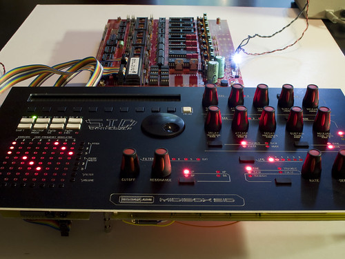
CS5 by JuhaKauppinen, on Flickr
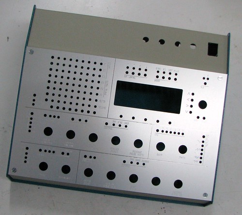
MB-6582 frontpanel testing on enclosure by JoeLMutantE, on Flickr
-
I guess this means I have to pull my finger out and get a batch of those power switch/socket PCBs made up... :)
Would it be more sensible to have them shipped with the cases? I like any idea that saves me from more packing and customs forms :frantics:
-
What version of MIDIbox SID are you using?
I vaguely recall there was an issue with Multi engine and control of the filter... but I got TK to fix it a long time ago. It was an issue with how the filter cutoff depth for a SID was the sum of the filter cutoff depth for each single osc "voice"... thus each voice played in isolation could only get up to 1/3 the maximum depth. I may be remembering it wrong... I'll have to dig through my old emails.
Perhaps this is related somehow... what's hard to determine is whether you are observing a difference in SIDs, a firmware bug or a hardware fault.
I'll have a play on my MB-6582 and see if I can get a difference between a single-osc Lead patch and a single-osc Multi patch.
-
Also, I've never heard SIDs have any self-oscillating filter squeal unless I used feedback pots (audio out -> audio in, with filter "Ext In" param enabled). Are you using feedback pots? Are you using the typical filter capacitors (470pF for 6581, 22nF for 8580/6582)?
-
One thing that might be related to your issue... the 6581 and 8580/6582 have different filters (obviously), and also there's a difference in how the cutoff frequency registers work. TK has made allowances for this by making the filter range adjustable in the Ensemble.
ACh: selects the audio channel: L (Left), R (Right) or LR (both)
Min/Max: this is a global, patch independent minimum/maximum value which scales the Cutoff between the given range. It allows you to calibrate your SID (especially the 6582 and 8580) for a suitable operation range. In general 000/FFF (full range) is fine for a 6581, 000/600 are recommented for 6582 and 8580.
Log: this function applies a logarithmic curve over filter CutOff values which are sent to the SID. By doing so, it linearizes the CutOff of a 6582/8580. It should especially activated, if the keytracking function is used. It shouldn't be activated for 6581s.
The default for all Ensembles is related to whichever version of the firmware was present when the Ensemble "bankstick" was formatted... so if you switch SID types, the Ensemble might have filter settings which don't match the SID.
So check those settings and see if it makes a difference, if not, I'll try to help diagnose your problem some more.
-
EPIC LULZ
THX GEEZERS I NEEDED A LAFF
YOU CAN HAZ 8 SIDS
-
Yes. But I am busy packing kits, busy doing other things, and lazy.
-
I've started using these:
http://www.sureelectronics.net/goods.php?id=1033
It's fairly standard pinout and dimensions.
When people are requested to confirm their order for a batch, I suggest this one as an alternative:
http://character-lcd-lcds.shopeio.com/inventory/details.asp?id=935&cat=Lcds&sub=Character%20Lcd
You will need to check dimensions AND the header pinout AND the header position. i.e. I have bought one LCD off eBay that had the backlight pins 15 and 16 swapped. Also the Optrex STEP displays are awesome, but their header pinout has the backlight pins at the other end of the header, so 14 pins correctly align with the sammichSID base, but the backlight pins don't, so you need to do a bit of a fix. I can send you details if you plan to get one.
Advice to everyone: let me check the LCD you plan to use.
-
Sorry it took so long, I should have suggested a short with LCD much earlier. You're not the first to have this problem magically disappear when I suggest detaching the LCD :wink:
-
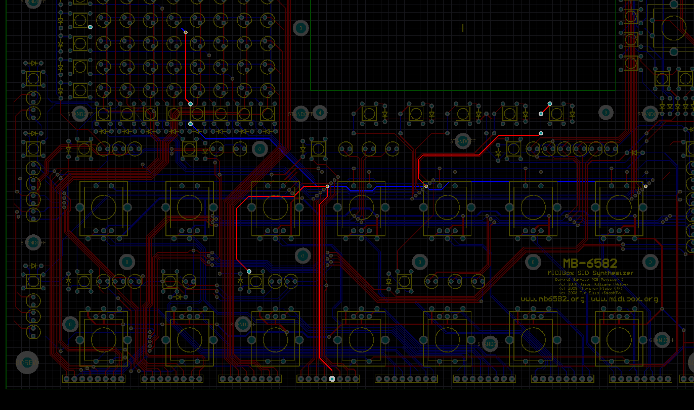
The LCD could be shorting with the "Select 5" switch. Check that first.
Then check the attached picture showing what is connected to that pin. Some vias are overlapped by encoders. It's unlikely but possible that an encoder is touching that via. AFAIK all the encoders I've seen have plastic feet so the metal base is not touching the PCB, but it's worth checking anyway.
-
I have my MB6582 almost finished. But still needed to sort out the PSU.
So i wanted to start soldering the components on it, but i ran into a bit of a problem. As suggested by the MB6582 surface partlist i ordered 2200uf 25V caps. Those are 7,5 RM with 1,0mm legs. But to my suprisse the mainboard has a big silkscreen but 5,0 RM 0,8mm position for both the caps.
As the rectified voltage goes way past 18 Volts i don't think its right to put in a 16Volt variant. But still dont understand why a 25V part is suggested as it wont fit the board...
Isn't this a bug or something which needs to be changed?
It's a bit of legacy and the fact that big electros come in different sizes depending on value, voltage rating AND some other magic factors like high temperature, low leakage etc.
The footprint on the PCB fit the 2200uF 16V caps I had in hand at the time of my prototype. AFAIK the rectified voltage does not go way past 18V, it is more like 11-15V under load. In addition, SmashTV assured me that the high-temp Xircon rated to 16V are safe to use. (Similarly, I "get away with" Xircon 2200uF 16V electros in sammichSID for the 9V regulation).
However, the original MIDIbox MIDIbox SID C64 optimized PSU schematic uses a 2200uF 25V for the 9V rectification and a 2200uF 16V on the 5V suppy (not that it's really required but doesn't hurt).
So you are right... the "25V" in the parts list was adopted from the schematic, but not what SmashTV supplies or what I have used in the past... so I changed it. I also saw your note, thanks!
-
-
The latest version of MIDIbox SID V2 Synth firmware is recommended and will always work with sammichSID. The only difference between "setup_sammich_sid.hex" and the other firmware files is handling the specific control surface, the synth engine is identical. So there will never come a time when you can't upgrade to the latest firmware.
-
This is good news, perhaps.
Look at the PDF I attached. Those LEDs have one thing in common - their "anodes" are all connected to R1, then R1 is connected to pin 15 (yes, pin 15 I am sure!) of IC4.
So first, check you are really testing pin 15. Then check the pads of R1 and IC4 pin 15. Check continuity between IC4 pin 15 and the upper pin of R1, then between the lower pin of R1 and the anodes (left) pins of those six LEDs.
-
wtf... did I write pin 15? I meant pin 16.
Both IC3 and IC4 have 5V on pin 16 and ground on pin 8. Refer to the voltage tests page of the build guide. I am referring to the exact same pins which are labelled with coloured dots for testing the voltage (5V or Ground).
FYI nearly all "logic" ICs have identical Vdd/Vss (5V/ground) pins... top-right and bottom-left (where pin 1 is top-left). This is also why the 8 outputs of a 74HC595 aren't all on one side (i.e. pin 1-8).
-
The "powerboard" is just a simple PCB with the same power socket and rocker switch as I use on sammichSID. It is designed to work well with a Core32 PCB. Since the switch is DPDT, one pole is used to control power going into Core32:J1, and the other pole can open/close Core32:J17 so that if power is being supplied to J1, J17 is open (don't use USB power), and if power is not being supplied to J1, J17 is closed (use USB power). Thus if either USB or DC power is connected, the switch will work as an on/off switch. If both USB and DC power are connected, the switch controls which is used.
You don't really need this PCB, it's just for convenience. I originally designed it for phunk's BLM16x16 but it is also useful for MB-SEQ, so I will get a small batch made and sell them bulk order style along with the switch and socket.
-
You should check again that you're following the instructions correctly.
It makes no sense that you had some LEDs light up via the test firmware, but now can't make them light manually.
So... you say the voltage tests are good... you SHOULD be able to light at least some of the LEDs this way.
If you still can't, test for continuity between the IC socket pins and the LED leads they connect to. Refer to the PDF.
-
If the SID isn't killing the C64, then it probably won't kill the sammichSID. I haven't heard of a case where a dead SID could damage the PCB it is in, so it should be safe. I would recommend testing it quickly, if you don't hear the bootup sounds, disconnect power immediately, just in case.
-
It be diz one..........I just measured it at 14v ac when set on 12v.....could be the problemo?
Maybe. You could probably set this to 9V AC, it might then output ~12V AC under full load.
It's a bit hard to test voltage on the pins marked "12V" while the control surface is attached... but do a test without the control surface (or maybe with the LCD removed from the PCB and plugged into the base). Test what voltage you get on the "12V" pins using the 9V AC setting on the PSU... this is with SIDs installed and LCD if you can be bothered... (you'll need to replace the transistor first). If you're getting something over 10.5V DC on the "12V" marked pins (i.e. what will be going into the 7809) then that should be OK.
MB-6582 troubleshooting
in Testing/Troubleshooting
Posted
First, make sure you are not using a heatsink that is connected between the voltage regulators, as this will not work for PSU Option B (the voltage regulators have different "grounds").
Uploading should take less than a minute. Something is wrong here, so you should remove the SIDs and solve the uploading problem, as well as the voltage problem.
Even if uploading did work, you say the 12V supply is not correct, so 6581s will not be making any sound anyway, even assuming you have set the jumpers so they were connected to the 12V supply (another possible point of failure). You cannot expect to get anything audio-related working until you resolve issues with voltages, check the PIC is working, check MIDI In/Out is working correctly (J11 jumper set correctly, for example), get uploads to take only a minute, with "use feedback from core" checked (if it's the old MIOS Studio).