

Wilba
-
Posts
3,310 -
Joined
-
Last visited
-
Days Won
2
Content Type
Profiles
Forums
Blogs
Gallery
Posts posted by Wilba
-
-
My 2 cents:
Washers aren't absolutely required, but cheap enough to get if you want. There's plenty of clearance around the holes for a standard M3 screw head (well, for Philips head at least), so I don't know what Hawkeye means by "make room for solder pads".
Spring washers are like lock washers, they look like a ring that's been cut and bent. I think either will work.
I have no idea if aluminium spacers will stick as well as plated brass.
Regarding LEDs:
It's easy to set the resistors to suit whatever LEDs you use.
Ignore the lead standoffs. You can set the height of the LED to whatever you want, but it's easiest to set it to either flush with the panel or exactly the same height as the switch tops. For flat-top LEDs, flush with the panel looks best and is easy to do, just solder the LEDs before the switches, so the panel can be put flat against something so the LEDs don't protrude past that while soldering.
-
I must admit, from the photos this looks quite badly made. I certainly don't like the idea of mains power wires insulated by a few bits of electrical tape!
For your own safety, I recommend not powering this unit again with mains power.
If it was mine, I'd start by ripping out the transformer and rebuilding it using power from a plugpack. The schematics are all available at www.ucapps.de you just need to look at the MIDIbox SID section and the Core and SID module sections. But I'm suspecting the problem is power related and the connections between boards are probably still OK... if someone can supply it with the required power, it will probably fire up again and be back in business.
-
The designer of the SID chip thought it might be cool to "chain" multiple SIDs by connecting the audio out to audio in of another SID. But it doesn't quite work that nicely since they're a little bit too noisy.
Also, the audio in can optionally go through the filter (see "ExtIn" parameter in MIDIbox SID). This is useful if you want to filter external audio with the SID filter, or add a "feedback" pot so you get more filter resonance.
-
I performed the backlight test annd this is what I got:
- the led lights up
- the led light is absolutely not affected by backlight trimpot settings
- the voltages are +5V at B+ and +3,13V at B-
- if I connect the two boards the backlight is still off
- the voltages measured on the top of control board are +5V at B+ and +1,16V at B-
When I do the same test with a green LED, I get voltage at B- of 2.77V with trimpot fully anticlockwise and 2.60V with trimpot fully clockwise. The difference in brightness is very small. Maybe you're using a red LED for testing, and the voltage drop is 1.8V so these results are "normal" for a working backlight circuit. Or something else could be wrong, I'm not sure.
Last time I did this test, the LED didn't work, and I wasn't getting those kind of voltages and replacing the BC337 fixed it. But I don't think you need to because you are getting some current sinking from the BC337. So now I think that it's most likely the LCD backlight is faulty and not your PCB... so the easiest way to prove this is just send you a new LCD and header.
-
-
Ok, I bought a new power supply which is regulated 600 mA 12V tip-positive. I checked the "no load" at 12V on the power supply and it gives me exactly 12V so, as Wilba suggested, it is supposed to be regulated.
I set the JBL shunt on 12V position, then I put a shunt on JR4, no shunts on JPB and the JP shunt in 6581 position. I checked the voltage in orange points and it gave me 10,5V.
Once connected the two boards the LCD came to life as I saw backlight and the "squares" displayed on its upper row, but after 5 minutes the backlight started to blink and in the end it went totally off; I can still see the squares row, so the LCD is working.
As far as I can check I cannot understand where the problem is. Is the LCD backlight definitely dead?
Possibly, but equally possible is a bad solder joint in the brightness pot, the BC337, or a dead BC337.
Note I've run my LCD backlight with a similar setup and not killed it, but I don't set the brightness pot past halfway. Was the brightness pot set to minimum (fully anti-clockwise)? or did you have it at maximum? It might be relevant to what could have gone wrong.
It also could be too much current load, but that seems unlikely with 600mA rating and no SIDs installed.
What kind of power supply is it? If it's switchmode, they can sometimes do crazy things that I can't explain.
I recommend testing the backlight pins on the base PCB with a LED. As above:
If you want to test the backlight circuit, you can do this by setting JR4/JBL to "low-power" backlight settings (no JR4, JBL="5V") and inserting an LED into the top two pins of J16 header (cathode in pin 16 "B-", anode in pin 15 "B+").
Test the voltages of the B+ and B- pins relative to ground and report them here... it will help work out what is wrong.
Try turning the brightness pot, check that the backlight circuit is actually limiting current. If the LED lights and you can change its brightness, the problem is probably with the LCD backlight. If the LED doesn't light at all, then the LCD backlight is probably OK and there's something wrong with the current limiting circuit (the BC337), though the LCD backlight could also be dead too. I recently fixed a problem where the LCD backlight, the LCD logic AND the BC337 were dead. Don't ask me how that happened, but it can.
Do a few tests and get back to me via email... it might be quicker to just assume the LCD is dead and I send you a new one... but you could try to replace the BC337 first.
As I have two 6581 and a 12V regulated power supply I have to set both the two shunts in JPB, right?
JBP, not JPB, but yes. Those shunts are essential to getting the "orange points" (also the SID voltage) exactly 12V. But this is unrelated to your LCD issue.... putting shunts in JBP will only increase the voltage to the backlight to 12V, the problem isn't lack of voltage there (it did work without JBP shunts, it should again).
-
Those displays look OK. You need to compare the dimensions with the "standard" one, see here: http://www.midibox.org/dokuwiki/doku.php?id=wilba_mb_6582_control_surface_parts_list
You should look at the spacing of the corner mount holes and the size of the bezel (check it will fit in the hole). At first glance, it looks OK.
The red/black one I used is here: http://character-lcd-lcds.shopeio.com/inventory/details.asp?id=1287&cat=Lcds&sub=Character%20Lcd
-
Snoozr: Where is the LCD window?
-
What a coincidence... yesterday, my wife painted her nails with that stuff. :thumbsup:
-
-
Kickflip: if you have a finished MB-6582 that's only missing "Waldorf" knobs, I will sell you 15 of mine, black/transparent or black/red.
POIDH!
Offer expires in 1440 minutes.
-
Hi! This forum pets lovers?
I destitution to buy such a cat

Who has this already exist?
What is the kind and what his character?
-
(I believe I was the first to complete one from the 1st batch.. does that have historical value? Some would say yes)
I suppose... but it is offset by unpainted engraving and no protective paper to assist in painting it.
Should the lucky buyer want painted engraving, I have a spare top and rear panel, which I can post cheaply worldwide, I think 6 AUD will cover it.
-
Please share your trick of getting everyone to pay. I always get 5% of people wasting my time, saying they'll pay next week (and then don't) or just ignoring me completely, as if not replying is the same as cancelling. </rant> :mad:
-
You should mention this is the original first batch sammichSID with amber LCD and red LEDs.
Also whether it comes with SIDs or not.
Also POIDH.
-
If it has a polarity switch i think it's safe to say its regulated.
Absolutely not. Most DC power supplies (especially the multi-voltage ones) have reversible tips, regardless of whether they are regulated or not.
The best way of checking if it is regulated is by using a multi-meter. The "no load" voltage should be exactly the voltage you expect (i.e. 12V) and not something way higher (like 15V).
In this case, the voltage is higher than 12V because it's unregulated. Take out the shunts in JBP, this is ONLY required in the special case of using a regulated 12V DC power supply to power 6581 SIDs.
Set the brightness pot to fully anti-clockwise.
Assuming you are using the high-power LCD I sell...
Check the shunt in JR4 is in.
Check the shunt in JBL is in "12V"
Remove all ICs, connect the boards, power it up. If you don't get any backlight or "squares" on the LCD, then you'll need to check solder joints on the headers connecting the LCD to the base PCB.
If you want to test the backlight circuit, you can do this by setting JR4/JBL to "low-power" backlight settings (no JR4, JBL="5V") and inserting an LED into the top two pins of J16 header (cathode in pin 16, anode in pin 15).
-
Points labelled "12V" won't be 12V if you are using an unregulated power supply. Start a new thread and tell us what power supply you are using, the voltage, AC or DC, current rating, etc.
-
@All: here's some audio demo with a bunch of patches I created during the first days of using the Shruthi. Due to the limitied but clear interface, this was a real joy!
Which filter board are you using?
-
I haven't built one but I like it.
BTW it wasn't "inspired by" sammichSID... sammichSID was first shown while Oliver had already designed his original Shruti-1. But I will agree that some people's cases are obviously similar:

"Maya" 1/4 by mutable.instruments, on Flickr
Now I'm inspired to do a remix/ripoff of the idea using a Core32 instead :wink:
-
Topic moved to Fleamarket.
Your issues might be related to the power supply, maybe also the LCD backlight brightness is too high, or you didn't put the shunt in JBL correctly for high-power LCDs. You're welcome to create a new topic to discuss this, or just email me about it.
-
I wouldn't request anything less than 100pcs from Sulzer... they're being quite nice dealing with people directly (where there isn't some stupid distributor like Neutrik interfering with sales). If you think other people might want some, I can get 100pcs of each and sell what you don't want.
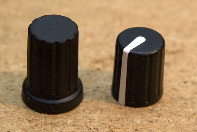
Can you post pictures of the other two knobs?
-
Wilba, do you have a suggestion on heatsinks inside the Sammich? Clearance seemed to be an issue there. I have some of FuzzyLizards sinks but it didn't look like they would fit in the Sammich.
I have some too. They look like they might have enough clearance with the top PCB, but then not with each other or with the filter caps. So you'd need to fold the fins up a bit and then trim them short, and also maybe chop off fins that have clearance issues with the caps, or bend the caps down a bit.
It might be easier to just stick some other kind of heatsinks onto the SIDs.... these aren't permanent, it's just a layer of double-sided tape holding them on.
http://www.zalman.com/ENG/product/Product_Read.asp?idx=136
.jpg)
-
I last bought 3000pcs Rean P401 knobs direct from Sulzer (2000pcs went to SmashTV for the MB-SEQ kits).
The MOQ is 1000pcs but I was able to get 100pcs of another type in the same order.
So if you're stuck getting exactly what you need, I could run a mini bulk order, get another 1000pcs of P401 and an assortment of other types (min/mult 100pcs).
As a rough estimate of price, here's what I got last time:
100 pcs P675-S-09-D6-S price CHF 26.70 per 100 pcs
P675 is a nice knob too.
-


Super cheap 20x4 Green Backlit LCDs
in Parts Archive
Posted
Thanks for the tip!
Note that discontinued doesn't mean they're not good quality... LCD manufacturers will often discontinue a model and replace it with an exactly identical model with perhaps a newer controller or different backlight.