

Wilba
-
Posts
3,310 -
Joined
-
Last visited
-
Days Won
2
Content Type
Profiles
Forums
Blogs
Gallery
Posts posted by Wilba
-
-
Yes, I got all the stock that was available from that source, around 4000pcs 6582A and 500pcs 6582.
-
They can't be referring to 6582A SIDs which I sold, they won't work in a SidStation (wrong voltage, wrong filter caps). IMHO the supply was genuinely scarce, and they got lucky and found more 6581R4AR that weren't broken or cleaned-up pulls from C64s.
-
-
In my control surface PCB, I put pads for the extra pins for encoders with switches so all the switches are in parallel and on a single DIN input, so you could use them for the "temporary fast" function. However, the Re'an P401 knob (which I used) will grab the encoder bushing when you push them down, and they can get stuck down, so I haven't used them this way (yet). That could be fixed by disassembling the encoder and filing down the bushing by 1mm or so, which I will probably do when I build up my 2nd MB-SEQ.
-
I really like the small form factor of the sammich sid. Sadly, I did not get in to order a kit on time.
You may have missed the "last" batch, but since I've got over 50 pre-orders, I will be doing another batch in February.
If you want something sooner, or you're keen on making your own CS and case, etc. I have a few sammichSID base PCBs spare.
-
That blue LCD is nice! I wish it came in 2x40 so I could replace my original MB-6582's dead PLED display.
If anyone is interested, Amanita said he got the blue LCD from Crystalfontz, but due to it being thinner than your average LED array backlight LCD, he mounted it above the control surface PCB so the gap between LCD and top panel wasn't so big. Mounting it above meant using an even longer male header than I put in the kits.
Amanita, what brand/type of paint did you use? Can I haz close-up of the paint job? Nicely done, BTW.
-
-
-
:rolleyes: This looks shopped. I can tell from the pixels, and the Aussie car with the Aussie licence plate and the Aussie crane service.
-
Mine is better than yours, assuming you even have one, which you don't, I know you're bluffing, I can tell from the pixels and having seen your bluff before, and fail...
-
do too!
-
POIDH
-
|: yeah,huh :|
NUH UH!
-
yeah huh!
nuh uh!
-
nuh uh!
-
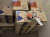
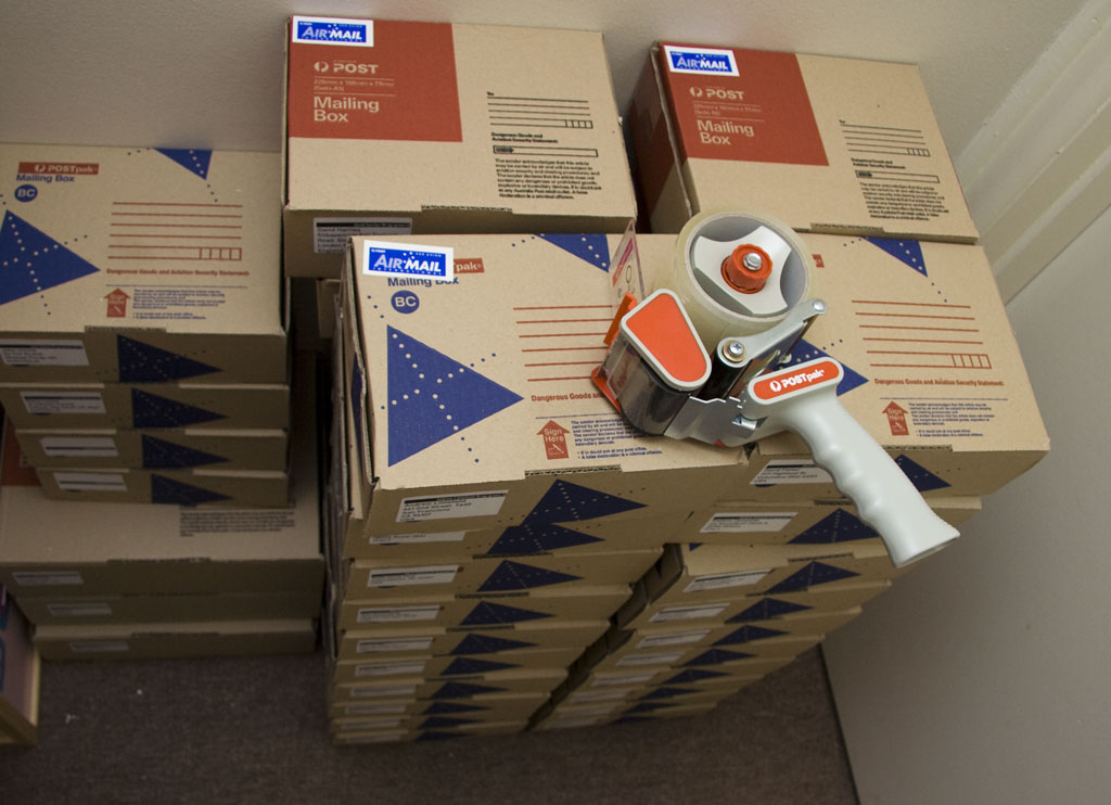
What are you doing, nILS? You can not pretend to be me! You are not crazy! You do not pack hundreds of kits! You don't even own a packing tape gun!
-
I have emailed everyone that sent their details to grizz already.
If you did not receive an email, or want to join this bulk order, just email me: Jason.S.Williams@gmail.com
There won't be any "This bulk order is OPEN/CLOSED" type posts. This will be an ongoing bulk order while I am still selling sammichFM kits, so you can contact me at any time to get some OPL3 chipsets, and if I have spares, I will sell them, if I don't have spares, you can wait until I get more.
That is all. Carry on.
-
Randomly swapping SIDs is not a solution. You didn't learn where the noise was coming from, the SIDs, the PCB, the filter caps, bad solder joints, etc.
I recommend you send all your SIDs to nILS for proper testing (and disposal of faulty ones).
-
Not easily, but it's possible.
If both devices are MIDIbox based, it might be easier to get one to send LCD commands through the other (maybe via CAN bus, or I2C or even MIDI).
Having them share the LCD bus is difficult to get right. Both devices would have to correctly handle when access to the LCD is given/taken, again if this was MIDIbox for both, they'd have to switch their ports to hi-Z when they don't have access... so there'd be a lot of coding to do... well, I could go on in great detail how I'd do it but I'll just give the short answer - it's possible, but there are easier ways to achieve the same thing.
If they are not both MIDIbox devices (i.e. you can't write code for both things you want to share the LCD), then it isn't possible - each device would assume it has sole access and wouldn't play nice, wouldn't refresh when switched to, etc.
-
I haven't finished Cherry Jammer yet... got distracted by sammichSID kits, sammichFM prototyping, etc. :whistle:
I like those switch caps... did you make them yourself?
-
ug glug glug
Thanks.
FYI the alternate pins are for encoders which I never use nor plan to ever use, but I can't resist putting them in just in case someone wants them.
-
In the first bulk order I did, I defined an "OPL3 chipset" as 1x YMF262 and 2x YAC512, since the intent was to fully stuff a MIDIbox "OPL3 module".
-
Picture the rotary encoder like two switches with a common pin. The common pin is pin 3, which is connected to ground. Pins 1 and 2 connect to the 74HC165. As the encoder turns, it closes each of the two switches in sequence, thus you can detect which direction the encoder is being turned by the "pulses". See here for more technical explanations: http://www.midibox.org/dokuwiki/doku.php?id=encoders
So it's normal for pin 1 and/or pin 2 to be connnected to pin 3, depending on the position of the shaft. You should do a continuity test between pin 1 and pin 3 while rotating the encoder, and listen for the beep going on and off. Repeat for between pin 2 and pin 3.
So to answer your questions:
1) Yes, but test more as I describe above.
2) You can't rule out faulty encoder at this stage.
3) Yes, see above. But also...
- check orientation of the resistor networks
- check no shorts between any of the IC pins
- check encoder pins aren't touching (and shorting with) the heatsink underneath
- did you upload the setup_sammich_sid.hex file (and not another one)?
- do the buttons work? Can you press 1st select button and get the Ensemble menu? Can you press Shift and get the Shift menu?
-
Maybe it's time someone wrote a dedicated MIDIbox FM patch editor/librarian... :D


Humpf puff argh frontpanel fitting issue
in MIDIbox SID
Posted
I solder the switches before the LEDs (or at least snap them into the PCB) so you know it will fit after soldering the LEDs... i.e. switches will be aligned with panel holes when you add the spacers to the panel etc. Did you not use the switches during the gluing of spacers?
Sometimes one or more of the switch shafts aren't perfectly vertical so they will catch on the edge of the panel hole. Unlike round LEDs which due to the round tops will guide themselves into the holes, the switches are flat at top, making it trickier sometimes. When this happens, you might need to use something pointy like a small screwdriver to push the few that are catching into the holes.