

dreamer
-
Posts
169 -
Joined
-
Last visited
-
Days Won
2
Content Type
Profiles
Forums
Blogs
Gallery
Posts posted by dreamer
-
-
Hello,
Maybe someone still has a non used / non soldered mb-6582 base PCB board. I'm very interested in buying it.
Grtz
-
that would be great :) I hate wrecking working C64 motherboards :D
-
Old PSU section on it.. (That reminds me need to have 7 pins din connector also) Lots of low quality components on it resulting in lots of noise. Bad soldering.. Strange behaviour on CS thats probally caused by bad soldering on the base. Also wrong jack outputs on the board that do not fit the layout.
When i listened to the new board i soldered i allready noticed the big difference in sound quallity.. Thats why i also want to replace the components on the old board. And hopefully also solving the behaviour of the CS board.
-
So the first mb6582 i build back in 2011 i have still laying around and i'm considering te repair / rebuild the base board (will be alot of work to desolder / solder almost everything). But i'm not sure if it's wise to re-use this board. I would love to have a new MB6582 baseboard or set but i don't know if someone still has them.
And I need a c64 style power switch. Or some other power switch that fits the layout. Are there any other power switches around that fit? Don't want to desolder another original C64.. :(
-
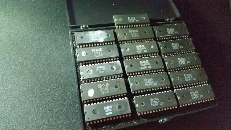
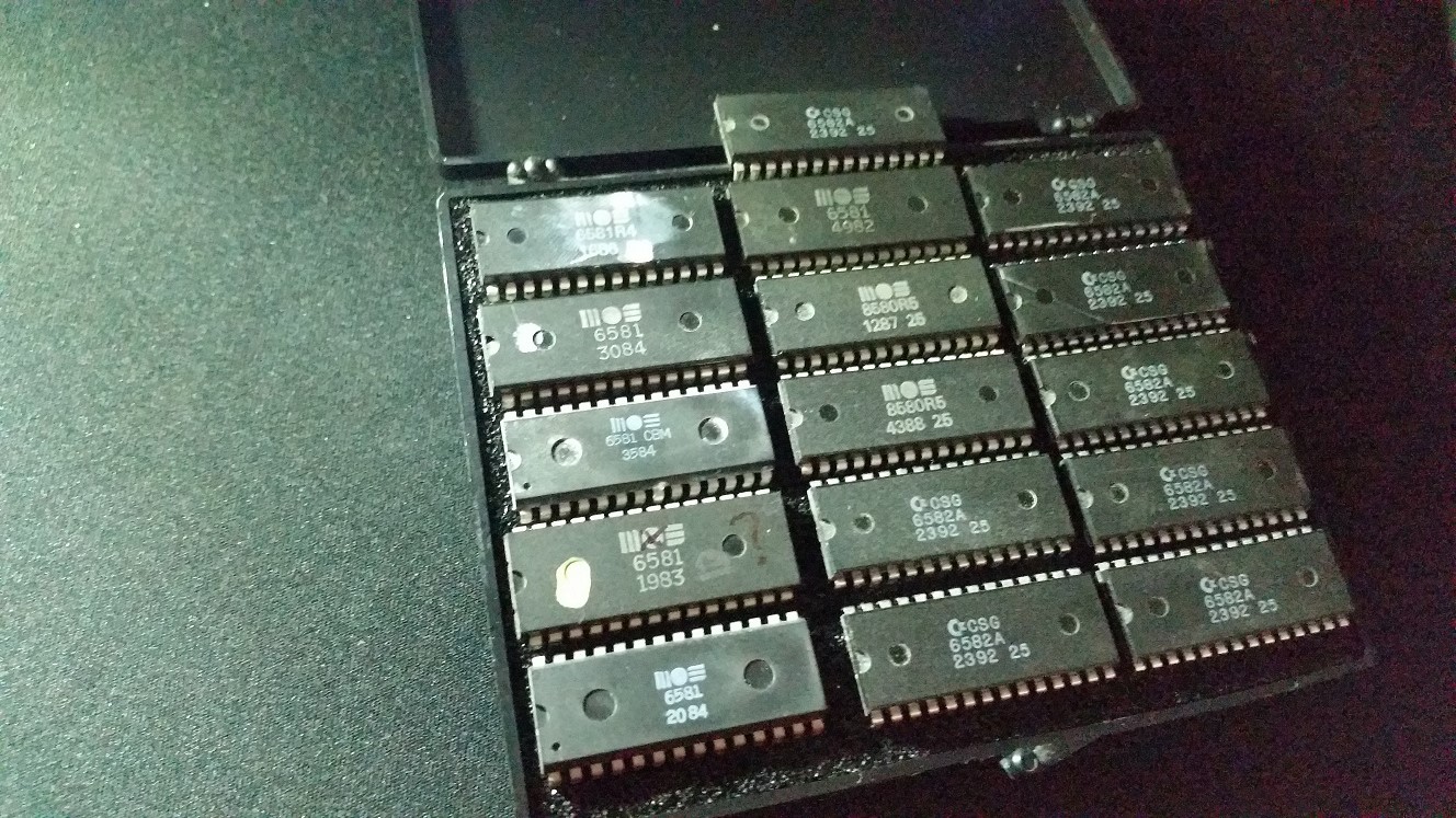
There won't be 8 6581 is my build. I only want 1 channel the have the 6581s. They sound way more dirtier then the other sids. And i like that. But in case 1 dies. i got some spares

But still we won't want that ofcourse. They are rare enough nowadays.
And JJonas.. any kits available?
Grtz
-
Above a soundlcip from the bassline engine running on 6581 12V sid chips. In this example you almost can't hear the vca problem. It's indeed low volume.
I also noticed that the 6581s get very hot.. This happens without anything covering the sids.. Almost so hot that you can't touch the outside..

-
ah i just googled the issue.. hmm.
Is it possible to do something about it.. Dont think so right?
Grtz
-
So i am bussy building a MB6582 and i am this far to start testing sound. I build a MB6582 with 12V - 9V and 5V options. So that i can use all types of sid chips if i want.
The problem is when i'm using 12V 6581 sid chips. When a "note off" is played you will still keep hearing the last played note but a little less louder. I don't have this issue when i'm using 9V 6582 / 8580 sid chips. So i guess there is a problem somewhere in the 12V power line. Any ideas where to look?
Grtz
-
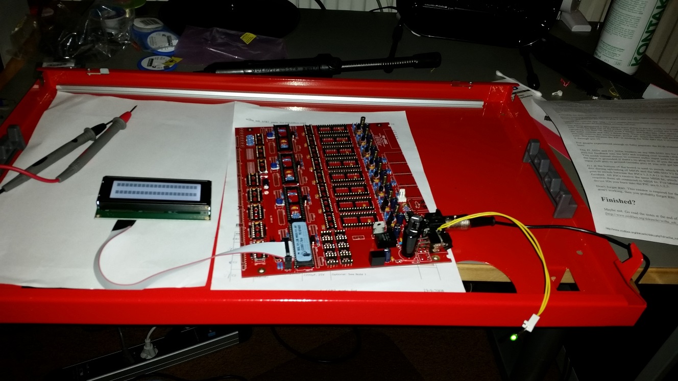
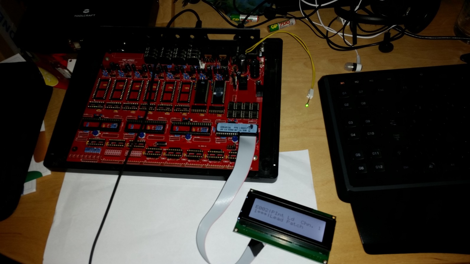
First time power up alway exciting moment :D

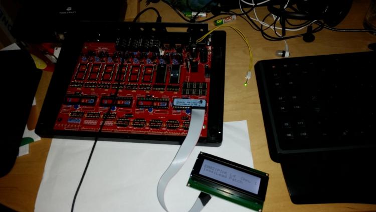
So it works
 but i have a issue when using 6581 12V sids. Will post this in the troubleshooting section.
-
So i finally got the voltages in
thanks all for helping.
But one strange little thing when i measure the voltages at J4 and combine with GND to see what voltages are running. I see a small increase of voltage in the beginning.
Example: I measure the 5V line and the moment i connect this i see a little jump to 8V and then back to 5V. The same with the other voltages. The moment i connect a small increase in voltage and the drops down. Is this expected because of the switching regulators or is there another problem somewhere.??
Grtz
-
Okay but i still need J72 pin 2-3 right otherwise i don't have 9V .

-
Yes i'm looking at it. It helps alot. But still can't exactly figure out how i get 12V. What i understand is that i should combine the 5V and 9V and then i would get 14V that will be regulated to 12V. But how i must combine those 2 is not completly clear to me.
Still i connected the "J72 pin 1" with "J72 pin 2-3" and now i get 8V on the 12V line..

-
so the 5V works

Still the 12V power circuit still does not give any voltage. I think the "J72 Pin1" Should be connected right?
-
hmmph i feel stupid now. I just lined up the dot on the 5V with the square on the PCB thinking that should be the input. I did the same with the 9V. I just checked the board layout and i can see my error now also. Thanks altitude for noticing it. When i'm home tonight i will turn it around hopefully the switcher is not broken now.
Grtz
-
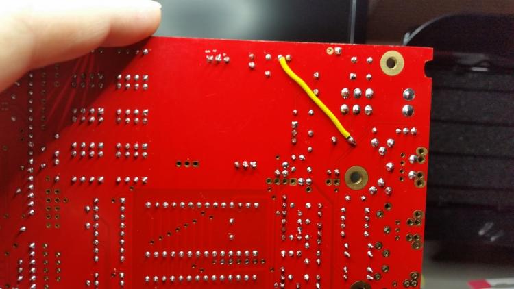
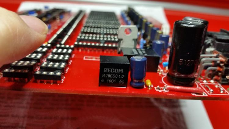
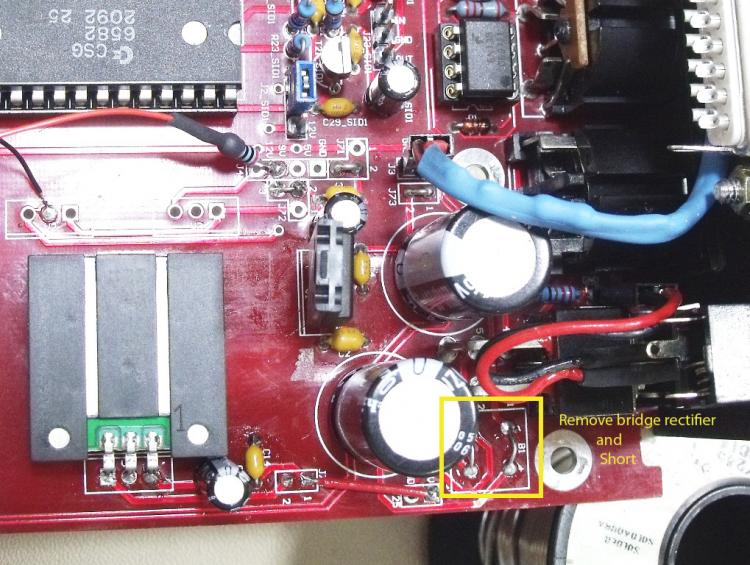
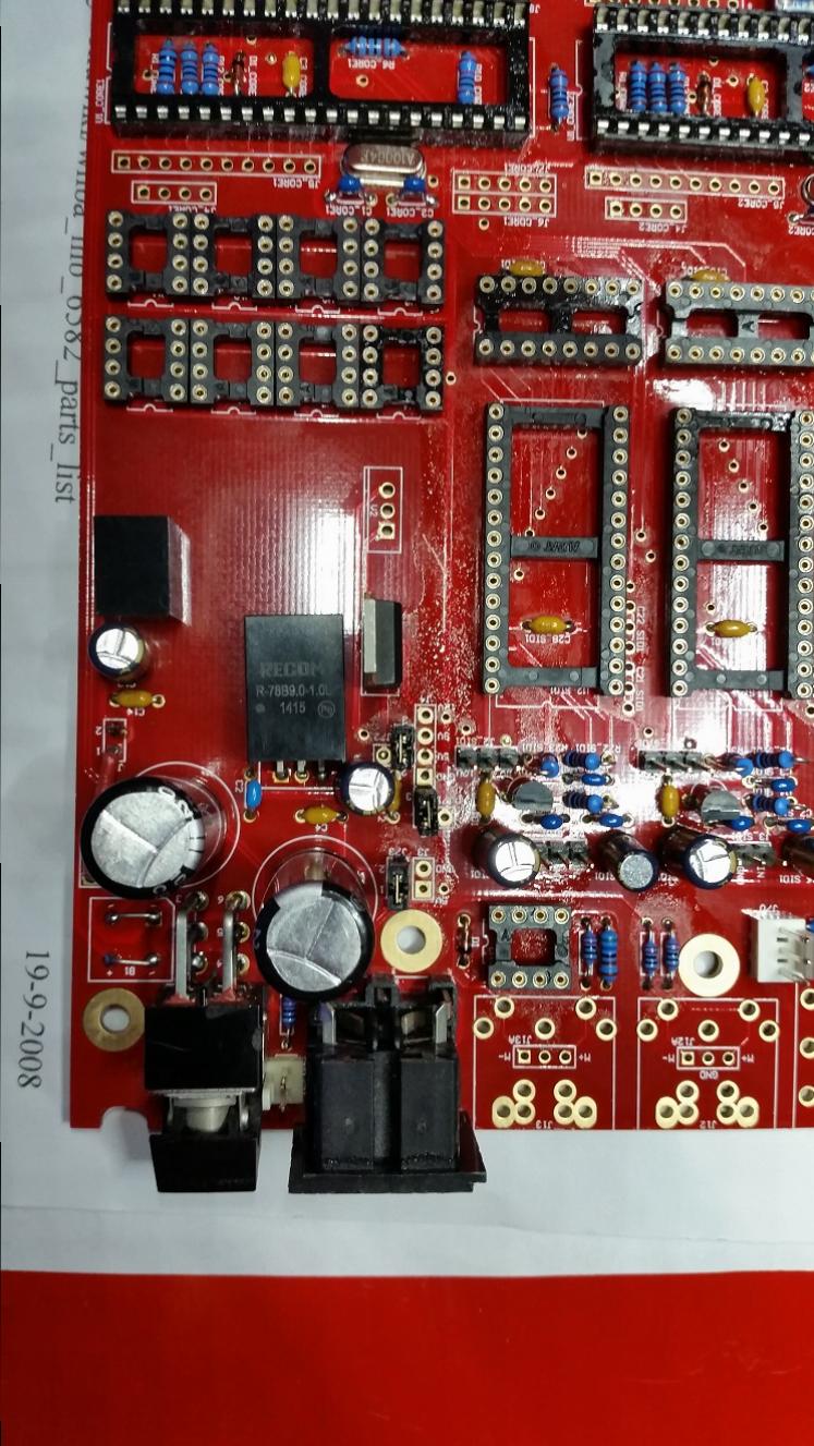
Here are the pictures of the board. Don't mind the greasy looking pic of the top view. This is from the PCB cleaner and is not conductive!
Still have to clean the board properly.
-
Hey,
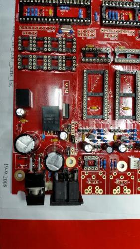
I just connected and power upped the MB6582 and started measuring voltages. I soldered the board like the picture attached to this message.
When i starting measuring i measured 15 VDC on the 5V power line --> NOK
als measured 9 VDC on the 9V power line --> OK
No voltage at all on the 12V power line --> NOK
any ideas what i did wrong?
-
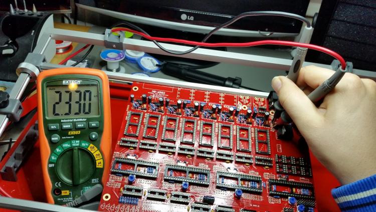
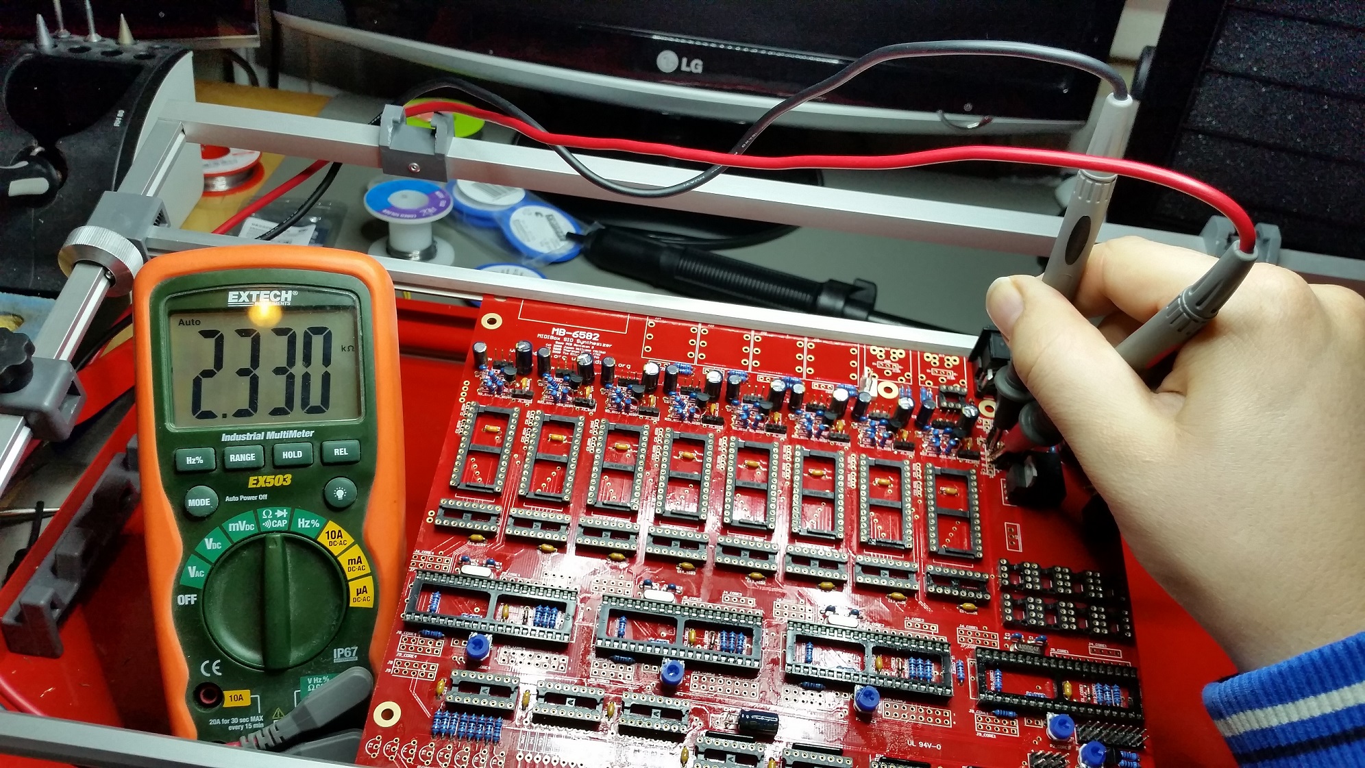
So i'm almost that far that i can put first power on my new MB6582 Base board. I wondering about a measurement before i continue.
In this example i'm measuring on J4 "pin GND" and "pin 5V" I did 2 measurments:
1st - Continuity test (With beep on multimeter) ==> NO BEEP WAS HEARD, so no continuity.
2nd - Ohm measurement ==> Measuring about 2.330 kOhm as seen in the picture.
Now my question is this a short or is this normal?
Grtz
-
I understand. Just making it easier for me because those labels are written on the base board. That's why i keep talking about it
 . Thanks for youre answers i think i've gathered enough info to power the board this way If not i will be back
-
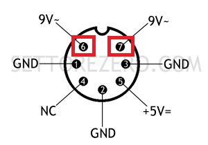
I changed the picture to a more exact drawing. So you are using the 9VAC to power it. Awesome


-
Thanks for youre answer. Almost ready
So are you using these to connect the power supply to the DIN socket?
-
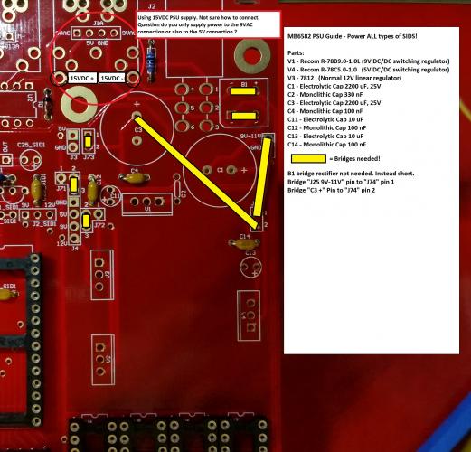
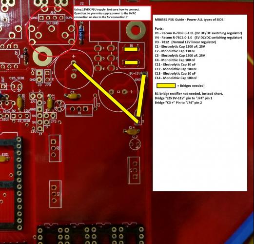
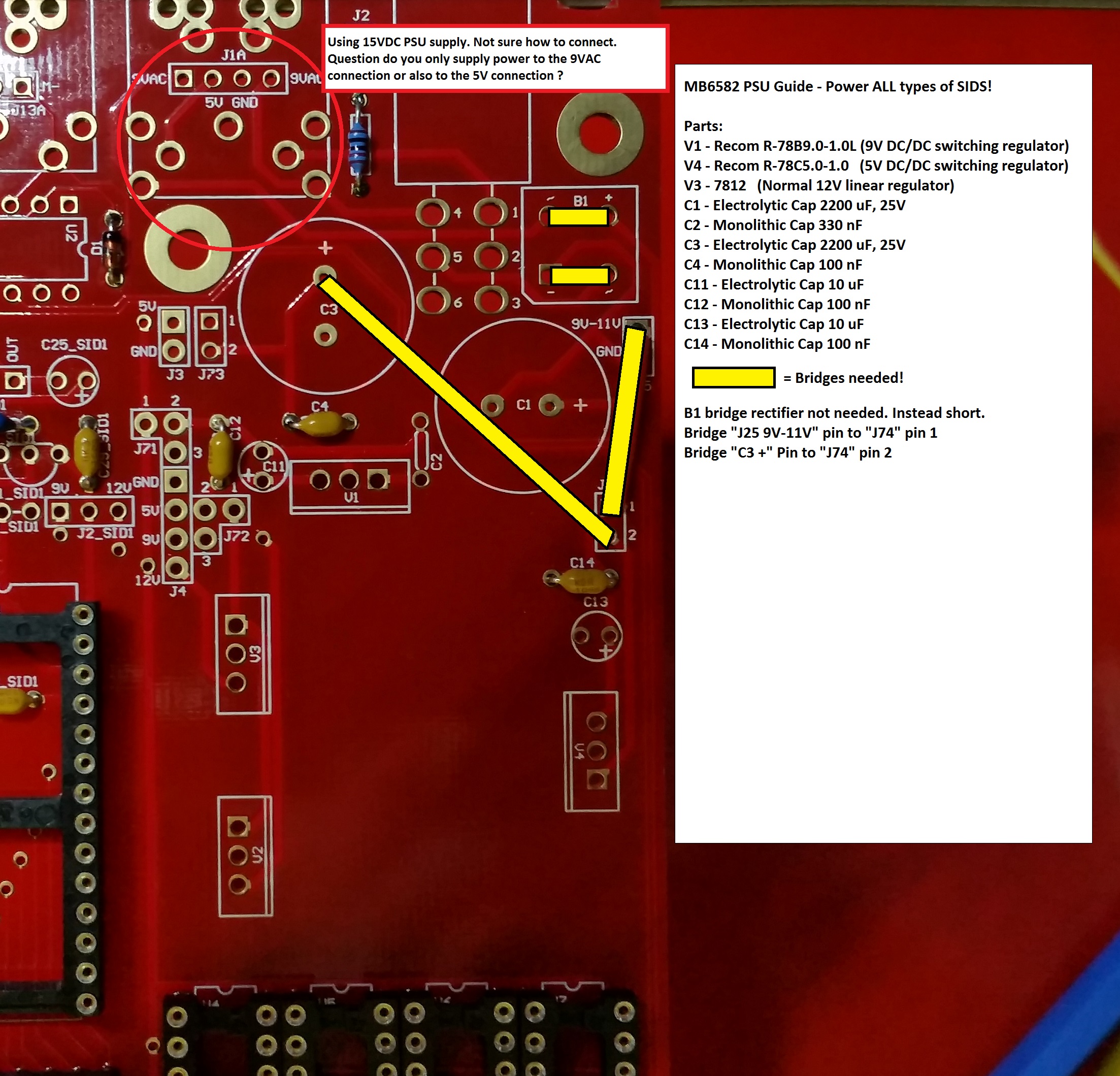
nog steeds beetje offtopic maar hopelijk krijg ik hier eerder antwoord. Ik ben bijna zover om het PSU gedeelte te solderen. Nu heb ik een guideline voor mezelf gemaakt aan de hand van alle info die ik heb kunnen vinden. Wil graag bevestigd hebben of het op deze manier correct is.
Ook weet ik niet precies op welke pinnen de 15VDC binnen moet komen. Of dit op de 9VAC OF 5V pinnen van J1A moet zij. Of dat dit 9VAC EN 5V moet zijn.
-
I'm almost ready to solder in the PSU section. I want to solder this like the picture i made as a guideline. If i understand everything this should be the correct way to solder this. Please take a look at it and verify that this is the correct way.
Only have 1 more question also shown in the picture. Is it correct that you only use the "J1A 9VAC" pins to supply the base board with 15VDC. Or do you also supply this to the "J1A 5V" pins?
-
Thanks for youre answer.
So for extra safety V3 must be stuffed with 7812. So i was thinking about this one:
This is a traco because of the dimensions. If my measurements are correct it will be a tight fit but should be possible to stuff all these on the top of the board.
All of them are recommended on 1A will this be enough?
And a 15VDC 2A powerbrick should be able to power it all right?
-
Hello Altitude,
So i started a new MB6582 and did a little bit research. If i want to use both 6581 and 8580 (6582) and i want to run this on a single 12VDC power supply i need both 9VDC and 5VDC DC/DC converters right?
Above 2 will be usable right?
Also i need to solder the base board with PSU option C right? And stuff V1 with the 9VDC?
So if what i mention above is correct and i solder this with all the bridges like you showed on youre picture this should work correct?
Finally the wire you have running from V2 to J71 9V connection is needed? And what value is the resistor that you are using on this wire?


Finally a new start to a MB6582 :)
in MIDIbox SID
Posted · Edited by dreamer
Almost there. The long and painfull waiting for the glue to cure