

dreamer
-
Posts
169 -
Joined
-
Last visited
-
Days Won
2
Content Type
Profiles
Forums
Blogs
Gallery
Posts posted by dreamer
-
-
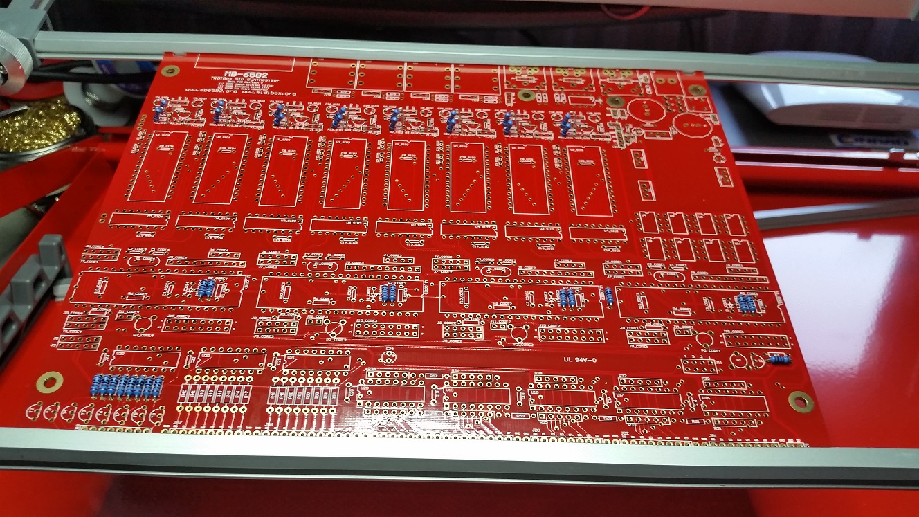
The first steps to a new MB6582 :D all 1kohms placed

-
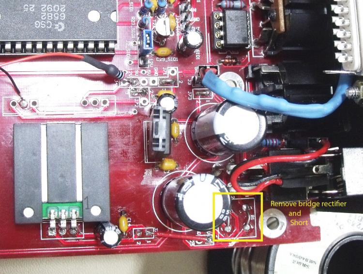
Dus als ik het goed begrijp doe je de MB6582 solderen met PSU optie C. Deze gebruikt V1 voor de 9V toch?
En als je daarna de brugjes maakt zoals altitude laat zien op de foto dan zal het allemaal in orde moeten zijn?
Ook zie ik een kabel lopen met een weerstand naar de 9V van J4. is deze ook nodig? En zowel enig idee welke waarde deze weerstand heeft?
-
Dus in principe is deze te gebruiken voor de 5VDC:
Is er nog iets wat ik moet hebben om ervoor te zorgen dat ik alle typen SIDS kan gebruiken door middel van 1 12VDC powersupply?
-
Volgende probleem. Ik ben nog steeds bezig om alle onderdeeltjes te "sourcen" en nu vraag ik me af waar ik JB-Weld vandaan kan halen in Nederland. De vorige build dacht ik een goede lijm gevonden te hebben ter vervanging van de JB-Weld, maar helaas bij iedere demontage van front panel + pcb breekt er regelmatig weer een afstandbusje af. Dus deze lijm is niet stevig genoeg.
Weet iemand een goede vervanger voor JB-Weld die ook nog een beetje makkelijk te bestellen is in Nederland?
-
i have some good caps for the SID filters but i was not talking only about the filters. But thanks for youre answer it's a very interesting topic that one.
-
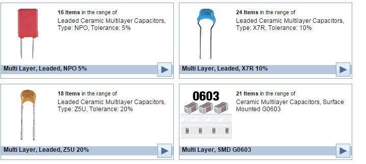
Just a general question. Which caps are best to use for MBSID projects (SMD caps not ofcourse)
The lower the tolerance the better?
-
Not using MB hardware but still did some sounds with originall C64.

-
Zodra ik mijn nieuwe spulletjes heb om mijn soldeer werkplekje te "moderniseren" kan ik beginnen met een nieuwe MB6582. Ook ga ik alle componenten die nodig zijn opnieuw bestellen en dit keer ook van een "degelijke" kwaliteit en hopelijk van 1 aanbieder die niet al te duur is om dit naar Nederland te sturen. Mijn vorige MB6582 is gesoldeerd met de goedkoopste componenten die ik maar kon vinden wat de kwaliteit niet ten goed komt.
-
dank je voor je antwoord zal eens rondkijken :)
-
i'm intrested in powering my mb6582 this way. Please show how you do youre voodoo jumpers?
-
Cool, ben sinds kort weer wat actiever. Heb weer zin om een 2e mb6582 te gaan bouwen. Had het opgegeven nadat de eerste een probleem had wat ik niet opgelost kreeg. De 2e wil ik ook het voeding gedeelte upgraden aan de hand van deze topic:
Iemand toevallig ervaring op deze manier, want ik zou nog wel wat tips kunnen gebruiken :D
-
so i recently gained interest again to solder my 2nd mb6582 because the first one has a problem i could not solve. This way of powering a mb6582 is very interesting. Is this topic the only topic with the details or is it somewhere else even better documented?
-
So after this i gave up on the mb6582. But now after a few years i have gained back the interest for getting things done. Also will upgrade my work area with better light and better tools to be able to troubleshoot better. But also decided to solder my 2nd mb6582 just to be able to troubleshoot hopefully even better. So if someone still is interested to input ideas on the problem i have, youre very welcome :D
-
also interested. When it will happen. :D i signed the form. I'm in for 2 kits
-
Would be great to hardware control the 9090. I will pass on beta though but definitly intrested if you have youre final design ready.
Grtz
-
So i checked common pin of the resistor network, and the orientation is OK.

Don't know what to do next.
grtz
-
hmm. still no cause found for my problem then. :pinch:
still lost..
-
hmm. How can i recognize this. The resistor network has SIL in its name. Could mean isolated. I did some measurements. Measured pin 1+2 = 10k measured pin 3+4 = 20k. But when i measure pin 1+3 = 10k also pin 1+4 = 10k also pin 1+5 = 10k and 1+6 = 10k.
So could the resistor network be fault?
-
Thanks for youre responses.
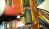
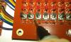
@wiba: Attached 2 pictures how i measured. I followed the buttons wiba marked blue.
I only measured for connection (beep, or no beep) for now. Measured as close as possible on the button on one side and on the other side on the connection of the input of the 165 on JD5. This is in the not pressed state i hear beep. Then i pressed in the switch and measured the other pins of the switch and also beep is heard. :shocked: This is repeated for all the buttons you marked blue. All beep the same.
@smashtv: I allready swapped the 165's and nothing changes. you mentioned the r57 r58 these are only needed when you have 5 pin resistor network right? I use 6 pins resistor network. How can i best measure the resistor network? Cause it should be 10k but probally due to bad measuring i sometimes measure 20k.
Except the buttons i mentioned it works great, not tried the all LED application though. but thats worries for later first i want these switches to work.
-
Still haven't found a cause for this problem. I checke the following:
- Measured at the 165's side if all signals from the wiring came in on the correct inputs --> No problem found

- Voltage measured not pressed arround 5.11 volt when button is pressed voltage drops to about 4.56 volt this happens to both working buttons and not working buttons. This happens at the button itself but also on connection of the 165 on the base board. Looks like everything is OK.
- I can't measure the 595's direclty because of the transistors.
So if i understand correct:
595's supply the voltage needed for operation when button is pressed 165's see voltage change on a input thus meaning they get a pulse. We got 8 inputs depending on what button is pressed the 165's translate to a bit for instance: 10110110 this is sended to the PIC and then the pic responds to it by sending the correct voltage to leds and send readout to LCD and the correct information to the SID. Correct me if i'm wrong.
So basicly when i send the following input 10110110 (this is OK at the CS<->165's) to the PIC it then has to send out information packages to different components (LCD,SID,595's) what if the information to the SID is obstructed could it be possible that the other information is not communicated back? Thus resulted in not working buttons, no read out to LCD and no change to the Sound generated?
I'm running out of ideas on this problem.

-
- checked all diodes on CS --> all OK
- Checked wiring again --> all OK
Also did some looking myself:
- The button labled MODE (filter section) is not working so i measured the behaviour of it. I measured the behaviour on the CS and followed the communication between this button and the connection at the 165. I compared this to a button that has no problem. I expected to see different behaviour but it was exactly the same, measured voltage. I repeated this with another button that was not working also that behaviour was the same as the working button. :wacko:
Now i wonder that it maybe possible the problems are on the base board instead of the CS. Is this possible? And any other tips?
grtz
-
Hey,
- Checked the soldering again --> nothing found
- Swapped the 595's --> No change, still the same buttons do not respond.
Can't find whats causing this, more tips?
Grtz
-
Are the 595's for the switches. I thought the 165's were.
That means i was concentrating on the wrong IC's.
Thanks for the heads up.
-
Hello all,
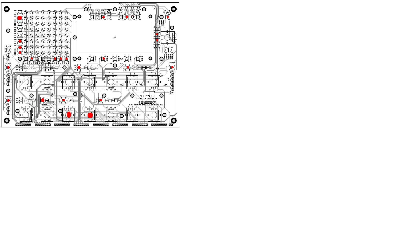
Can someone point out some good tips how to determine the cause why lots of buttons don't respond on the CS. I attached a file where i marked the buttons that don't work.
Actions taken:
- Checked the CS and Base for faulty soldering --> Did not found anything
- Checked on the Base the resistor networks --> Replaced 1 resistor network but did not help.
- Checked all cables and beeped for connection from CS to Base --> All OK.
- Measured some voltages and resistances of faulty buttons and compared with working buttons --> Nothing found
I would love to see some shematic that shows me if i push a button where the exact signal runs to. Its hard to rule out things step by step to find the cause of the problem this way. Anyone got some more tips what i can check?
Grtz


Finally a new start to a MB6582 :)
in MIDIbox SID
Posted · Edited by dreamer
I bought a ideal-tek PCSA-2. Very awesome tool. You can completly stuff youre board if you want then close the lid and turn it around to solder everything.