
Marxon
-
Posts
474 -
Joined
-
Last visited
-
Days Won
4
Content Type
Profiles
Forums
Blogs
Gallery
Everything posted by Marxon
-
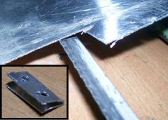
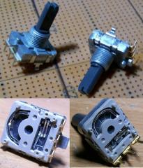
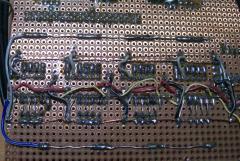
From the album: Marxon's M³ - MarxonMixvibesMidibox
-
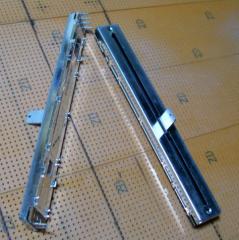
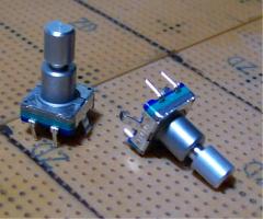
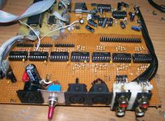
From the album: Marxon's M³ - MarxonMixvibesMidibox
-
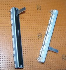
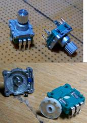
From the album: Marxon's M³ - MarxonMixvibesMidibox
-
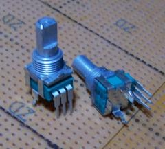
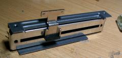
From the album: Marxon's M³ - MarxonMixvibesMidibox
-
From the album: Marxon's M³ - MarxonMixvibesMidibox
-
From the album: Marxon's M³ - MarxonMixvibesMidibox
-
From the album: Marxon's M³ - MarxonMixvibesMidibox
-
From the album: Marxon's M³ - MarxonMixvibesMidibox
-
It´s me again... But there are good news Finally it works now :smile: Good output, low background noise I simply forgot to connect audio gnd. Slap in my face... And the 5v issue: who cares ;)
-
Hi again :smile: I was reheating every soldering when i noticed a missing trace on my board. It is the 5v trace which goes to the bridge and from there to the rest of the board. But like i said in my last post there was 5v on Ic2 Pin 1, 3, 6, 9 even without the missing trace? So the new question is: where do the 5v come from?
-
Hi Midiboxers, after fixing my voltage issue, i still have a output problem :( It is very low and there is a lot of background noise: Testtone: test.mp3 I allready checked: 5V @ Ic1 Pin 1,7; Ic2 Pin 1, 3, 6, 9 +12V @ Ic3 Pin 4; Ic6 Pin 4 -12V @ Ic3 Pin 11; Ic6 Pin 11 polarity of c1, c3, c5, c7, c11 ,c16, c18, c20 ,c22, c24, c26, c31, c32, c33, c34 = checked replaced Ic3, Ic6 = no difference FM-Interconnection test = passed Any suggestions what could be the fault? May some other capaciator? Thanks for your help Best regards Marxon
-
 Thanks. should i take out my willem programmer and test it? ;)
 -
You are the master of 1´s and 0´s :smile:I am just a little solder guy. So i connect the LEDs like you think it is the best way to do. Oder auf deutsch: du wirst schon wissen was du tust :smile: Danke für die Info Gruß Marxon
-
Ja mein Englisch ist nicht das Beste... Aber wie immer: saubere Abeit von dir. Danke
-
Hi Midiboxers, i just wondering if it is possible to change the assignment of the OP 1-4 and Instr. 1-4 LEDs? Because there is no option in the cs_menu_io_tables... Or is it necessary to connect them like in the FM Dout schematic? Best regards Marxon
-
OK habs in meinem Gehirn korrigiert.
-
[solved] Address exceeds maximum range for this processor
Marxon replied to Marxon's topic in MIOS programming (Assembler)
Hi Thorsten, tanks for your fast reply! LOL! You are right they are also compiled. Damn i did not noticed this :/ Sorry for wasting your time! -
Hi all, if i try to compile one of the orginal FM 1.4 pic18f452.asm via make then i get a lot of "Address exceeds maximum range for this processor." make: *** [setup_pic18f452_mbfm_tk.hex] Error 1 error.txt I suspected there is may some pic18f4685 option enabled inside the asm but they are all turned off. The pic18f4685.asm are compiled successful. I have installed the correct version from the toolchain: SDCC 2.80 MYSYS 1.0.11 Gputils 0.14.3 (also tried 1.0) The forum search did not find a working solution. Someone know what to do? Best regards Marxon
-
From the album: Marxon's FM Synth
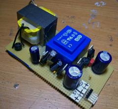
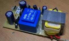
The PSU is consists of a 2x15V dual transformer for the +/-12V lines and a 12V transformer for the +5V line. -
From the album: Marxon's FM Synth
The PSU is consists of a 2x15V dual transformer for the +/-12V lines and a 12V transformer for the +5V line. -
From the album: Marxon's FM Synth
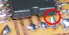
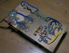
I covered "High Voltage" solderings with hot clue -
From the album: Marxon's FM Synth
-
From the album: Marxon's FM Synth
-
From the album: Marxon's FM Synth
-
From the album: Marxon's FM Synth
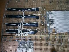
It does not look very professional, but it works :smile:

