Marxon
-
Posts
474 -
Joined
-
Last visited
-
Days Won
4
Content Type
Profiles
Forums
Blogs
Gallery
Everything posted by Marxon
-
Hi all, here are the Midibox NG manuals as pdf version. I will try to keep them updated :smile: UPDATE 2013-08-31 all manuals reworked UPDATE 2013-05-25 new manuals UPDATE 2013-04-01 added NG Manual - .ngr Scripts.pdf UPDATE 2013-03-18 NG Manual - .ngc Config.pdf MIDIbox NG User Manual - Hardware and LCD Options, Installation.pdf MIDIbox NG User Manual - First Steps and Standard Control Surface.pdf MIDIbox NG User Manual - .NGC .NGL Configuration Files and .NGR Scripts.pdf MIDIbox NG User Manual - Source Code and 'Complete Documentation'.pdf Best regards Marxon
-
Hi, here is another one: SID Manual.pdf Best regards Marxon
-
OPL voltage problems (fixed) -> now PSU voltage problem
Marxon replied to Marxon's topic in Testing/Troubleshooting
I guess you are right. Just checked the datasheet from my LCD: The led backlight already needs 300mA. I will try your suggestion with the second +V rail. Have some 7809 here... My transformer has 2x1,6A Some 2x3A is allready ordered :smile: OK lets start the next round.... Again, thanks a lot for your support! Best regards Marxon EDIT: any recommendations which capaciator values to use? -
OPL voltage problems (fixed) -> now PSU voltage problem
Marxon replied to Marxon's topic in Testing/Troubleshooting
Hi again yogi and all others! It is unbelievable how many different connections somebody can measure, before locating the real problem :smile: Ladys and Gentelman: it is the PSU! As long there is less current drawn from 5V (only the Core without LCD for example ;) everything is ok. But if there is more current drawn 5V drops to +12V drops to 6,8V -12V remains -12V I am using this PSU from the forum: Only difference: i have "dual" transformer with 2x15V outputs. I connected the outputs like this: At the 7812 +12v output i connected an additional 7805 circuit (2200uF-330nF-7805-10uF-100nF) to get the 5V. So what could cause this behavoir? I guess the 7812 is faulty, but right now i have no other one for testing. Any other ideas? Best regards Marxon -
OPL voltage problems (fixed) -> now PSU voltage problem
Marxon replied to Marxon's topic in Testing/Troubleshooting
Can´t sleep... must fix it :rolleyes: Here my next tests: PSU:+12/-12V/Gnd --> OPL:J3 PSU:Gnd --> Core J2:Vss PSU:+5V --> Core J2:Vdd and OPL J1:Vdd no LCD connected RESULTS: OPL J3:-12V to OPL J3:Gnd = -12V OPL J3:12V to OPL J3:Gnd = 12V OPL J1:Vdd to OPL J3:Gnd = 5V Core boots up. next: PSU:+12/-12V/Gnd --> OPL:J3 PSU:Gnd --> Core J2:Vss PSU:+5V --> Core J2:Vdd and OPL J1:Vdd LCD connected RESULTS: OPL J3:-12V to OPL J3:Gnd = -12V OPL J3:12V to OPL J3:Gnd = 6,5V OPL J1:Vdd to OPL J3:Gnd = 5V Core does not boot. next: PSU:Gnd --> OPL J3:Gnd and Core J2:Vss PSU:+5V --> OPL J1:Vdd and Core J2:Vdd LCD connected RESULTS: PSU:+12 to PSU:Gnd = +12V PSU:-12 to PSU:Gnd = -12V PSU:+5 to PSU:Gnd = +5V Core boots up. LCD is working. Strange? -
OPL voltage problems (fixed) -> now PSU voltage problem
Marxon replied to Marxon's topic in Testing/Troubleshooting
I have tested every single Core(PIC)-Opls(YMF) line to figure out if a certain one causes the problem: -Core (Testtone app) and Opl module powered with 5V, -LCD connected (LCD shows "Testone Generator") Result: CORE PIC:pin24 to OPL J2:WR (YMF:pin6,8) was the problem! But there was no short circuit to see... So it has to be under the YMF :smile: I tried to bend it up a little bit, very carefully. And then i blowed as strong as i can from all sides to the chip, connected everything again: It works! Unfortunately, now it doesn´t boot with +/-12V connected. But i guess tomorrow after some sleeping, it will be fixed too. So far, thanks for your supoort yogi! Best regards Marxon -
OPL voltage problems (fixed) -> now PSU voltage problem
Marxon replied to Marxon's topic in Testing/Troubleshooting
Hi Yogi, thank you very much for trying to help me! Yes the Core does boot when nothing connected. The Core-Opl interconnection test voltages are also OK (without Core - Opl J2/1 and J2/2 connection) It does also boot with Core-OPL 5V connection (without Core - Opl J2/1 and J2/2 connection). If i connect J2/1 or J2/2 the Core reboots again and again which means i get the "boot-up midi-message" every 2-3 seconds and the 5V drops down to 4,3V(!) So we getting closer to the problem, right? Best regards Marxon EDIT: I fear my OPL3 chip is dead :( When the OPL module is powered with 5V, nothing else connected, which voltages should there be if i measure the OPL:J2 module pins to Vss? -
Hi everybody, i have some voltage problems with my OPL module. If i connect J2/1 or J2/2 to the core it doesnt boot anymore. After searching the forum i found a topic which said to measure the following: 1) With everything disconnected, what voltage do you read from IC1:12(Vss) to IC1:11(Vdd) on the core module? 5V 2) When you connect Core:J1 to OPL3:J1 only - what voltage do you read from IC1:12(Vss) to IC1:1(Vdd) on the OPL board? 5V 3) Does the LED light up with just the Core:J2 > OPL:J1 connection? Yes 4) With no wires connected anywhere - What's the resistance between the following pin pairs on the OPL module: IC3:4 and IC1:12 = 3,6M IC3:4 and IC1:1 = 3,8M IC3:11 and IC1:12 = 0,2M increasing to 2,0M IC3:11 and IC1:1 = nothing J3:V+ and J3:Gnd = 0,1M increasing to 2M J3:V- and J3:Gnd = 0,2M increasing to 2M J3:V+ and J3:V- = 16M 3) "I haven't attached the pull-up resistor for the CAN Bus." - the diode isn't there either? No diode. I guess there is something wrong with my +/- 12V right? Are there any other connection that i can measure to find the problem? Thanks a lot for your help! Marxon
-
Hi all, i digged out this old topic because i had the same problem. There was -17V on the 7912 output. Finally it turns out that it was increasing to -12V on load. Maybe this info is usefull for somebody else. Marxon
-
YAR - Yet another reminder ;) But once again: dont feel stressed :)
-
edit
-
Hi Thorsten, vielen Danke für deine schnelle Hilfe. Problem gelöst: Mit gputils Version 1.0.0 funktionierts. Hatte vorher Version 0.1.37. Kann man das verallgemeinern, es also evtl im Wiki ändern? Schönen Tag noch, Marxon
-
Hallo alle zusammen, Leider musste ich neulich mein System komplett neu installieren und somit auch die MIOS Toolchains. :( Mit MIOS32 via Eclipse bin ich fertig und macht keine Probleme, deswegen denke ich, dass auch meine MIOS8 Ordnerstrukturen und Umgebungsvariablen stimmen sollten, trotzdem erhalte ich diesen Fehler beim Versuch eine setup.asm zu compilen: D:\D.I.Y\MIOSSoftware\Sid_v2_042 make rm -rf *.cod *.lst *.err rm -rf *.hex gpasm -p p18f4685 -I./src -I ./i io -I ./modules/aout setup_6581 ./include/asm\mios.h:49:Error [179 file or directory make: *** [setup_6581.hex] Error 1 Leider fand ich im Forum bisher keine passende Lösung. Hat jemand eine Idee, weshalb der Fehler auftritt? Vielen Dank im voraus! Mfg Marxon
-
Ja ist denn heut schon Weihnachten?
-
Thanks, got it working! :ahappy: I disassembled an old mouse, used a 74HC14 schmitt trigger and connected it to my SeqV4:
-
Thanks for your work :thumbsup: Best regards Marxon
-
Two good news at once :thumbsup: I also cant await the release of Midibox NG :frantics: Best regards Marxon
-
Hi again TK, i dont want to get on your nerves :angel: but is this "current instrument" thing still on your todo list? Best regards Marxon
-
Thats great! Thanks
-
Hi everybody, i have some small suggestion for the Seq V4 mixer mode: It would be usefull to have a mixer page to send also relative de/increment values. Best regards Marxon
-
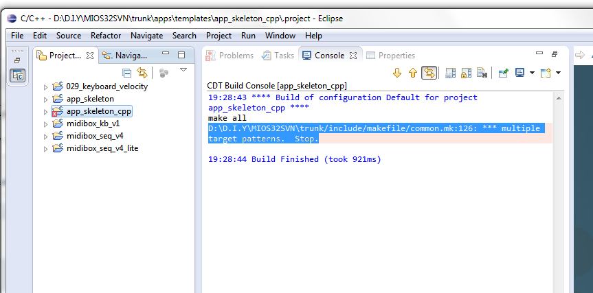
Hi again, the multiple target problem is fixed :) I changed my Eclipse´s build enviroment variables to MIOS32_PATH /D/D.I.Y/MIOS32SVN/trunk MIOS32_BIN_PATH ${MIOS32_PATH}/bin In my case i stored the content from the svnmios.midibox.org/svn.mios32 folder in D:\D.I.Y\MIOS32SVN Thanks for your advice TK! Best regards Marxon
-
Sorry, shame on me! But i have version 3.81.
-
Hi everybody, maybe someone can help me: I followed the Mois32 toolchain without problems and now i want to built the app_skeleton_cpp project but Eclipse gives me this error D:\D.I.Y\MIOS32SVN\trunk/include/makefile/common.mk:126: *** multiple target patterns. Stop. what coudt be the reason? Thanks for any advice. Best regards Marxon
-
Hi TK and all others, while browsing the web for different jogwheel/encoder types i found some interesting projects about using the sensor chip from an optical mouse. http://ferretrobotics.blogspot.de/2011/01/interfacing-optical-mouse-usb-with-pic.html and here more technical informations: http://www.ele.uva.es/~pedro/optoele/LEDs/Appnotes/opticalMouse.pdf http://www.avagotech.com/docs/AV02-1184EN Would this not give more then enough resolution? The Chip seems to be useable without additional circuits. It uses a ps/2 and a quadrouble output mode. Unfortunatelly i do not have the knowledgement to create a midibox compatible peace of hardware in reality. But maybe someone can use this informations ;) Best regards Marxon
-
Es gibt einige verschiedene Herangehensweisen zum Thema HiRes Encoder im Forum. Optisch, Magentisch oder doch mechanisch? Wie ist deine Meinung dazu? Wieviele Ticks/Umdrehung wären sinnvoll und zu welchem Preis. Oder hast du schon einen bestimmten Encoder im Fokus? Spenden wär kein Thema :) Gruß Marxon