All2u
-
Posts
28 -
Joined
-
Last visited
-
Days Won
1
Content Type
Profiles
Forums
Blogs
Gallery
Everything posted by All2u
-
MBHP MF_NG Impossible to upload MIOS via MIDI please Help
All2u replied to All2u's topic in Testing/Troubleshooting
Is there any solutions !? I start to thinking that this project is to complicated for me... -
Hello have you planned to build 8x1 pcb ? Best regards
-
MBHP MF_NG Impossible to upload MIOS via MIDI please Help
All2u replied to All2u's topic in Testing/Troubleshooting
I'm using MPLAB IDE v8.92 I've test with disable the ID reprogramming but it's not working within MIOS STUDIO (lots of aftertouch and pitchbend messages instead of MIOS request) The user ID is set to 00000000 Thanks for your help Best regards -
MBHP MF_NG Impossible to upload MIOS via MIDI please Help
All2u replied to All2u's topic in Testing/Troubleshooting
I've made this but it's not solved my problem !! Always the same issue... Best regards -
MBHP MF_NG Impossible to upload MIOS via MIDI please Help
All2u replied to All2u's topic in Testing/Troubleshooting
Hello Thorsten, first I flashed the PIC with the program and I mean it's well flashed by "all is ok" For end setting to fff I've just respect your instructions in the asm file. So what I don't understand is : What should I do after the PIC flashing ?! I'm french sorry for my poor english !! Thanks, best regards. All2u -
MBHP MF_NG Impossible to upload MIOS via MIDI please Help
All2u replied to All2u's topic in Testing/Troubleshooting
Thank you for your answer but I test it and it doesn't work perhaps I lost something !! I've programmed the PIC with Mplab IDE with the end setting to fff all is ok but when I put it to the core nothing happens in MIOS STUDIO ... Can you give me the good manipulation after the programming please ? Thanks by advance, Best regards. -
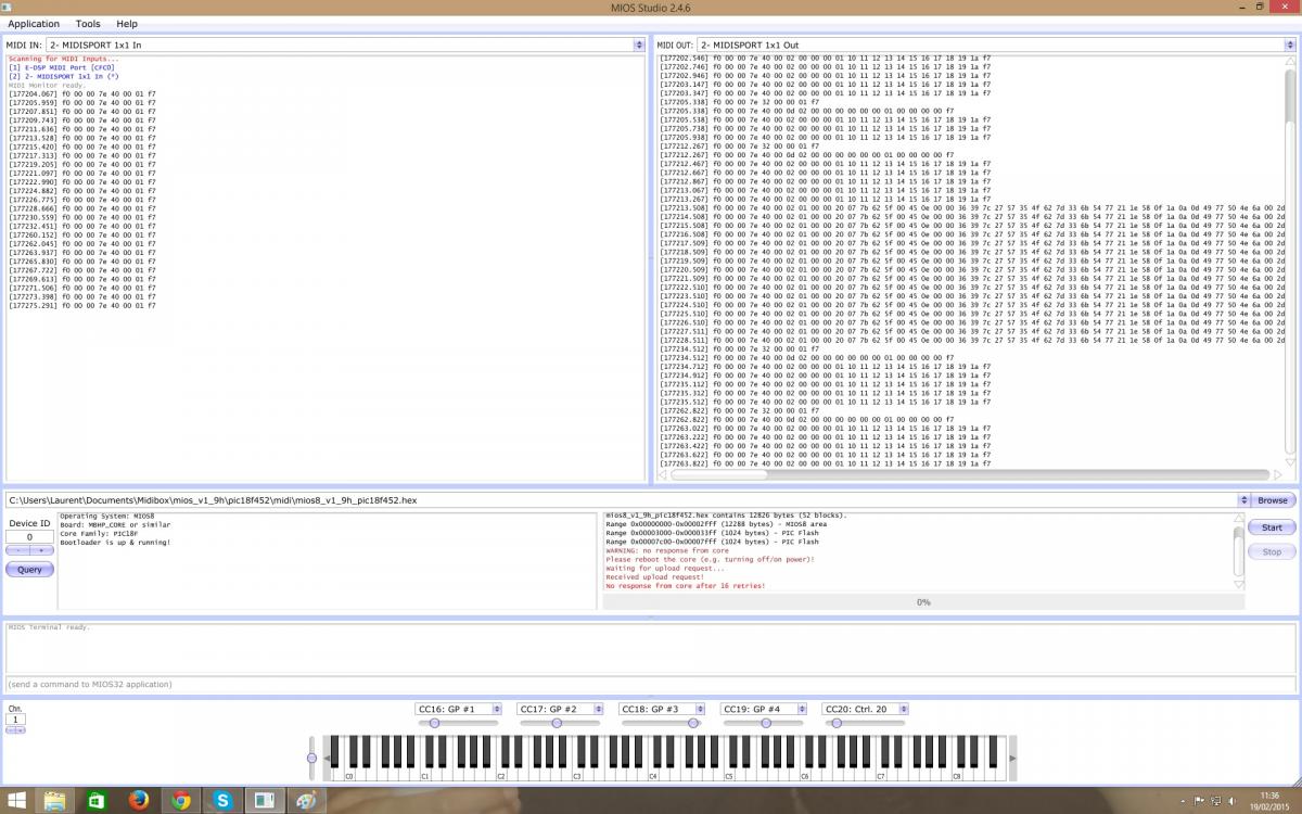
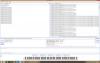
Hello all, I have a big problem to upload MIOS with MIOS Studio and it's make me crazy !!! So I have test with many midi support : - My internal E-MU 1616 - An external M-Audio MIDISPORT 1x1 and the MIDIBOX STM32F4 with the MIDI IO and the USB MIDI 4x4 driver nothing works always the same "No response from core after 16 retries!" message My core is programmed with a PICKIT3 and it's look ok It's send "[176405.191] f0 00 00 7e 40 00 01 f7" in loop that's seems ok MIOS STUDIO say "Bootloader is up & running!" that's ok but when I start the upload of the Mios program it's block The leds of the midi support blinking so it's confirmed that a midi message is send to the core I join a screen capture of the MIOS STUDIO to illustrate my problem and I hoped that someone could help me because it's very frustatring to blocked so near the goal Thanks by advance, best regards.
-
Hello Los Zelos, I have the same problem with my MF NG boards, I've you solved your problem ?! Best regards.
-
Thank you again Thorsten for your help !! I test this and repost my setup when it's ready for validation :phone: Best regards, All2u.
-
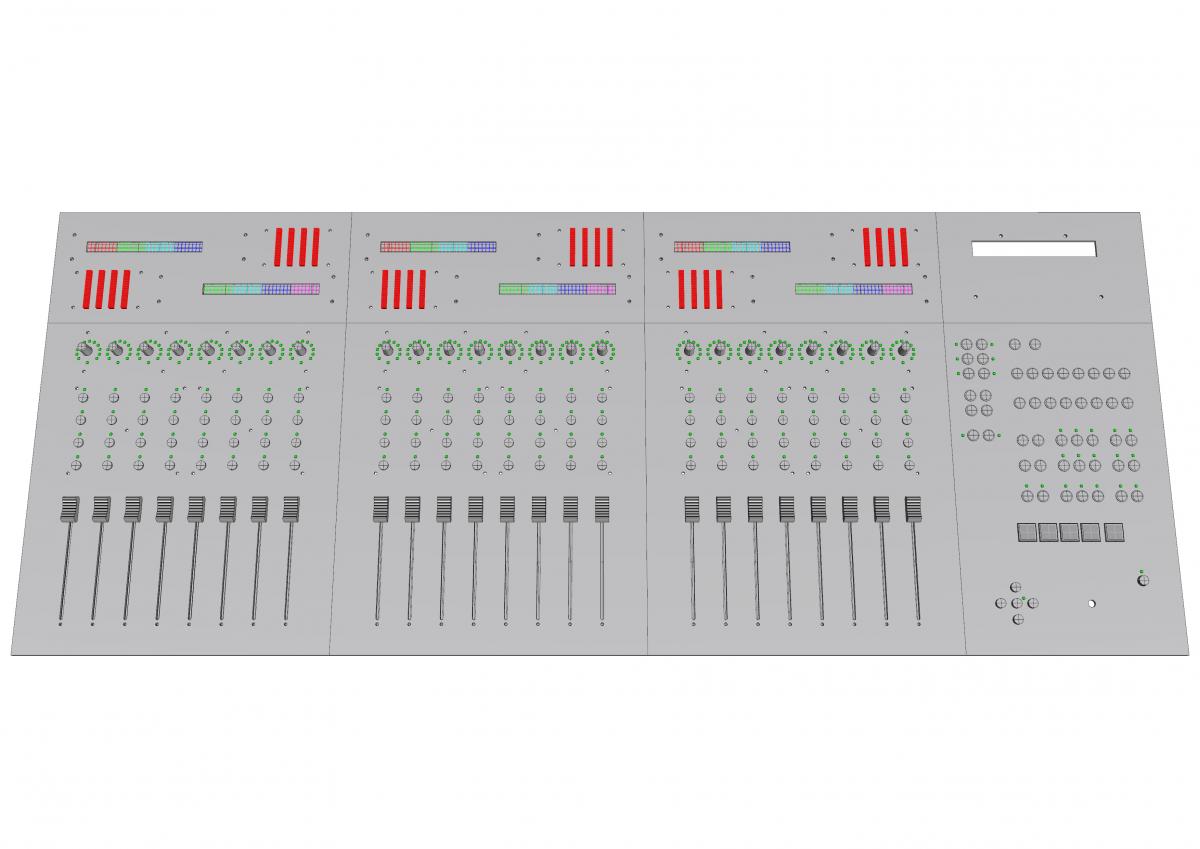
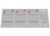
Hello all, I plan to build a 24 tracks midibox controller (See the attached image) and I have many questions about the ngc configuration file. So, for start this is my ngc file it isn't complete but this is a good point of start for me to understand how it's working : The questions are : 1 - Is the setup for buttons correct with differents ports routing ? 2 - What's the setup for the ledrings (to assignate the rings for each 24 channels) ? 3 - For the meters could I assign lc_meter_port=USB1 then USB2 and USB3 ? 4 - Why my setup returns all the time at default when I reboot ? (In MIOS STUDIO I've tape save default but nothing to do it's returns to default setup !!) So for the moments it's all, any suggestions will be welcome ! Thanks by advance, Best regards, All2u
-
Sorry it's working !!!! I don't know why but It's alive again, Anyway the problem seems to be in cubase the led digits don't react at the MTC. Anybody knows why ? Thank you, Best regards, Laurent.
-
Hello, I've already changing the configuration and it's not working !! all the digits says 8. So with common cathode it's display numbers changing with CC but on all the digits at same times. I hope I've been clear because it's frustrating... if not I could make a video for more explicit !! Thank you for your help Best regards, Laurent.
-
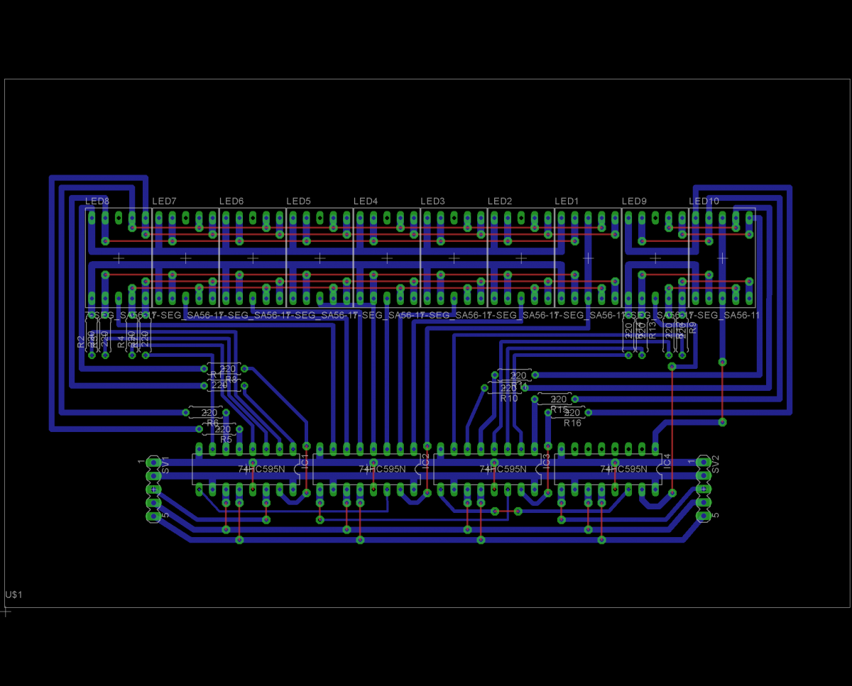
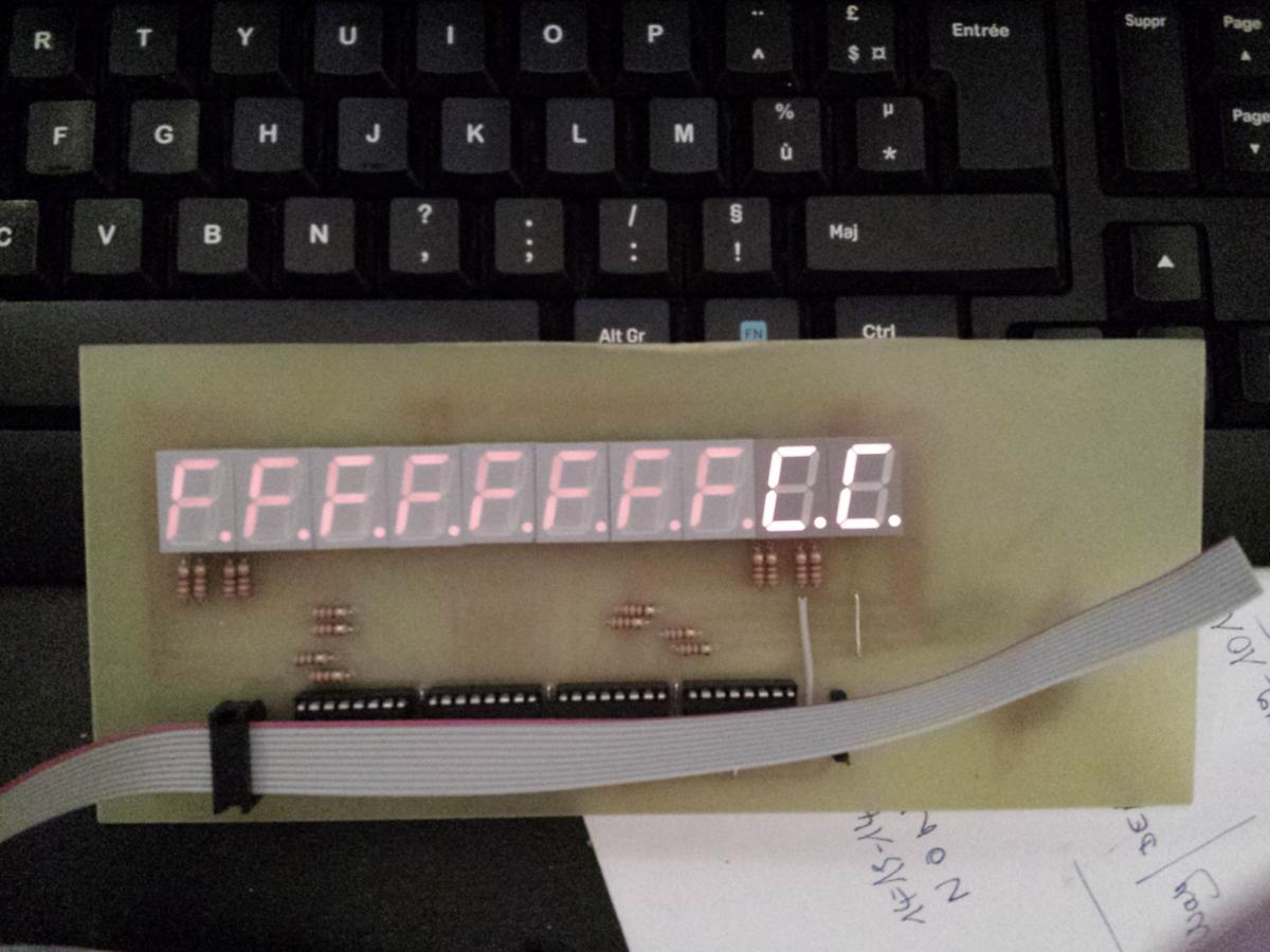
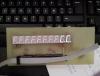
Hello there, I have made a pcb for 10 led digits but the problem is that all the led digit have the same number !! When I upload in mios the leddig2.ngc and I'm play with the cc64 to cc73 all the numbers is changing at the same time... Is someone have the same problem ? it's very boring. I join a photo of the problem and an image of my pcb design, if anyone would like the eagle file no problem. (sorry for my english I'm french) Thank you in advance Best regards.

-
nikel ça fait plaisir !! J'y pense si tu fais une midibox LC et que tu cherches des faders motorisés dis moi quoi !! A bientot et bonne continuation !
-
Olala !! abandonner !! deja !!! Alors que le meilleur reste a venir ça serait vraiment dommage !! Bon, j'ai une ou deux questions : Peux-tu faire une capture d'ecran quand tu upload avec le mios ? As-tu pensé au GM5 USB ?? ça change la vie ! si tu veux j'en ai un en rab !! Quel est ton projet ??
-
oui je passe effectivement par J11 pour connecter mon entrée midi seulement, la sortie étant fonctionnelle. je vais essayer de t'expliquer ! (sur l'image ne fait pas attention au gameport ni a tout ce qui est en rouge) MI est l'entrée midi (pin 4 ou 5 sur le schema ci-dessous) la flêche vers le bas est la masse ( pin 2 sur le schema ci-dessous) c'est tout ce que tu as a branché pour l'entrée ! et n'oublie pas de retirer l'optocoupleur et de passer R6 en 100k comme indiqué Voila, J'espere que ça t'aidera à avancer, j'ai essayé de faire au plus simple !! Bonne continuation !!
-
as tu testé ton optocoupleur ? Car chez moi je me suis passé de ce composant qui n'as jamais fonctionné !! Je passe par le port J11 et j'ai remplacé R6 par une résistance de 100 k Si tu veux des détails n'hésite pas !
-
bonsoir et bienvenue ! J'ai effectivement u ce problème et j'ai passé de longues heures à me casser la tête pour finir par me rendre compte que j'avais inversé des fils au niveau de l'entrée midi. je te conseille donc de commencer par bien vérifier si tu as bien tout branché au bon endroit Si ça ne résoud pas ton problème on essayera autre chose !! personnellement j' ai construit plusieurs core et ça n'est jamais fonctionné du premier coup donc faut tatonner :P Bon courage ! tiens nous au courant
-
My GM5 is here !! Thank you so much !!
-
salut ! J'ai fais ça avec 3dsmax et finaltoon !!
-
Me revoila après de longs mois de débogage et autres prises de tetes avec mes modules !! J'ai assez bien évolué dans la fabrication de ma LC puisque tous mes circuits sont réalisés et opérationels, reste que le circuit de alim a percé et complété. J'ai donc désormais mes 8 faders motorisés qui bougent (pas très bien pour le moment, alim pas assez puissante), mes boutons qui fonctionnent(reste encore à réalisé la deuxième moitié de la table) et mes leds qui s'allument, tout roule quoi !! J'ai également revu l'intégralité de ma face avant dont voici un aperçu rapide en 3d(manque quelques boutons encore à l'étude!) Voila c'est tout pour le moment bientot une petite video des faders et du reste surement !! Prochaine étape : fabrication de la face avant !!! pffff A bientot !
-
Très bon à savoir tout ça !! merci reboot ;D Junkyseb, est-ce tu as déja entendu parler des coffrets TEKO, ils ont une grande variété en forme et en taille!! essaye ça si tu trouve ton bonheur http://www.teko.it/Eng/SIZES/frame.htm A bientot
-
J'avais entendu parler du Lazertran mais est-ce que ça tiendra correctement sur du PVC ??! Sinon je serait chaud pour une commande groupée moxi, juste savoir le prix parce que j'ai un budget très serré en ce moment! Il me faudrait 2xA3, ça devrait suffire...
-
Pour l'impression de la face avant je pense utiliser du papier photo comme ci-dessus avec un film adhésif transparent pour éviter les taches !! Pour l'instant c'est encore à l'étude mais je n'ai rien trouvé de mieux malgrès mes recherches si vous avez d'autres idées elles sont les bienvenues...
-
Merci pour vos commentaires!!! ;D Comme promis voici les photos de mon avancement : le coffret en bois et tole : La face avant en PVC 2mm: La face avant,réalisée en fer blanc et dont les trous ne collent malheureusement pas avec les boutons : La première mise en place graphique : Voila pour l'instant ce qui m'as pris le plus clair de mon temps, la partie electronique est en attente faute de budget !!! :'( N'hésitez pas à laisser des critiques ou des conseils, je suis tout ouïe !! A bientot