syamajala
-
Posts
66 -
Joined
-
Last visited
-
Days Won
1
Content Type
Profiles
Forums
Blogs
Gallery
Everything posted by syamajala
-
The NT3881 is supposed to be HD44780 compatible. It looks like its supported by mios according to this, http://www.midibox.org/dokuwiki/doku.php?id=lcd&s[]=nt3881d I'll try the pots.
-
My lcd has a NT3881 chip on it. Is there anything special I need to do? I customized the source for my CS, and uploaded it but still haven't stuff the din and douts. I noticed once that when I played some notes on the fm the screen would flicker, but it still has black squares and blinking cursor.
-
i get a black squares on the lcd now. the one on the far left is blinking too. at least it seems to turn on with the din, dout, and lcd all connected. i still haven't stuffed the din and dout though.
-
has anyone tried using a 3d printer?
-
It is the lcd. I disconnected the din and dout, then tried to turn it on the fm again, and it still wasn't working. I disconnected the lcd and it started working. I used SIL connectors for the lcd and soldered everything else. I think I'm going to get rid of the SILs. I'm not completely sure if I hooked up the lcd correctly. I'm using an optrex C-51850NFJ-SLW-ADN. According to the manual, pins 1, 2, 3 are Vss (gnd), Vcc (supply for logic), and Vee (supply for lcd drive). I hooked up Vss to Vs on the core, Vee to Vo, and Vcc to Vd. Another thing is I'm not sure if I should use +5v or +!2v to power the lcd. The manual says the absolute maximum Vee should be is 13.5v, and the recommend range is between 4.4 and 5.2v. However, I'm not sure if I should worry about current. I built a power supply using NorthernLightX's schematic, I think the transformer I used is 4A, the 7805 is 1A , and the 7812 is 1A, but since everything needs 5v and the opl3 is the only thing I have hooked up to the 7812 should I use 12v for the lcd? I haven't done any current measurements yet.
-
I finished the CS for my fm, but it no longer turns on. The core and the opl3 module where working fine before I hooked up the lcd, din, and dout boards. So, where should I start looking? One thing I should mention, is that although I hooked up the din and dout boards, I didn't put in the shift registers yet. I thought that I would upload the proper application to the core before I put them in. Could that be the reason?
-
I have some rotary encoders that don't have any labels on them. How do I figure out the pin out to hook them up? I bought them from smashtv maybe 3 years ago and am just now finally getting around to using them. They are blue on the bottom. I can take a picture if that will help anyone with identifying them so I can find a data sheet.
-
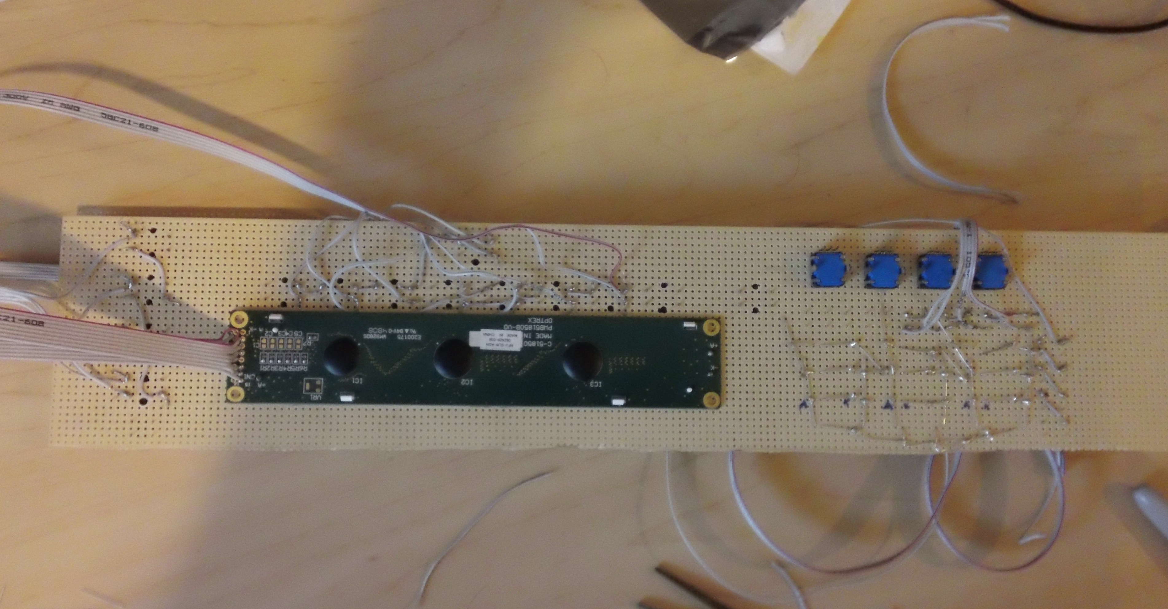
I made a mistake by putting the rotary encoders so close to one another. Its almost done now...
-
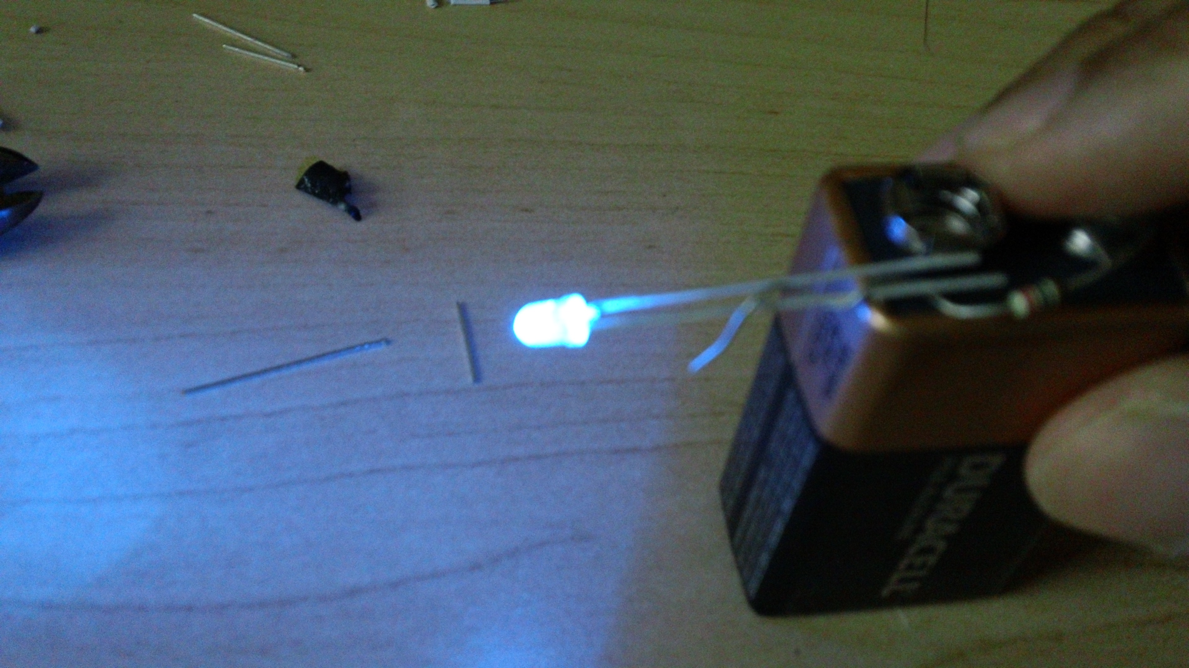
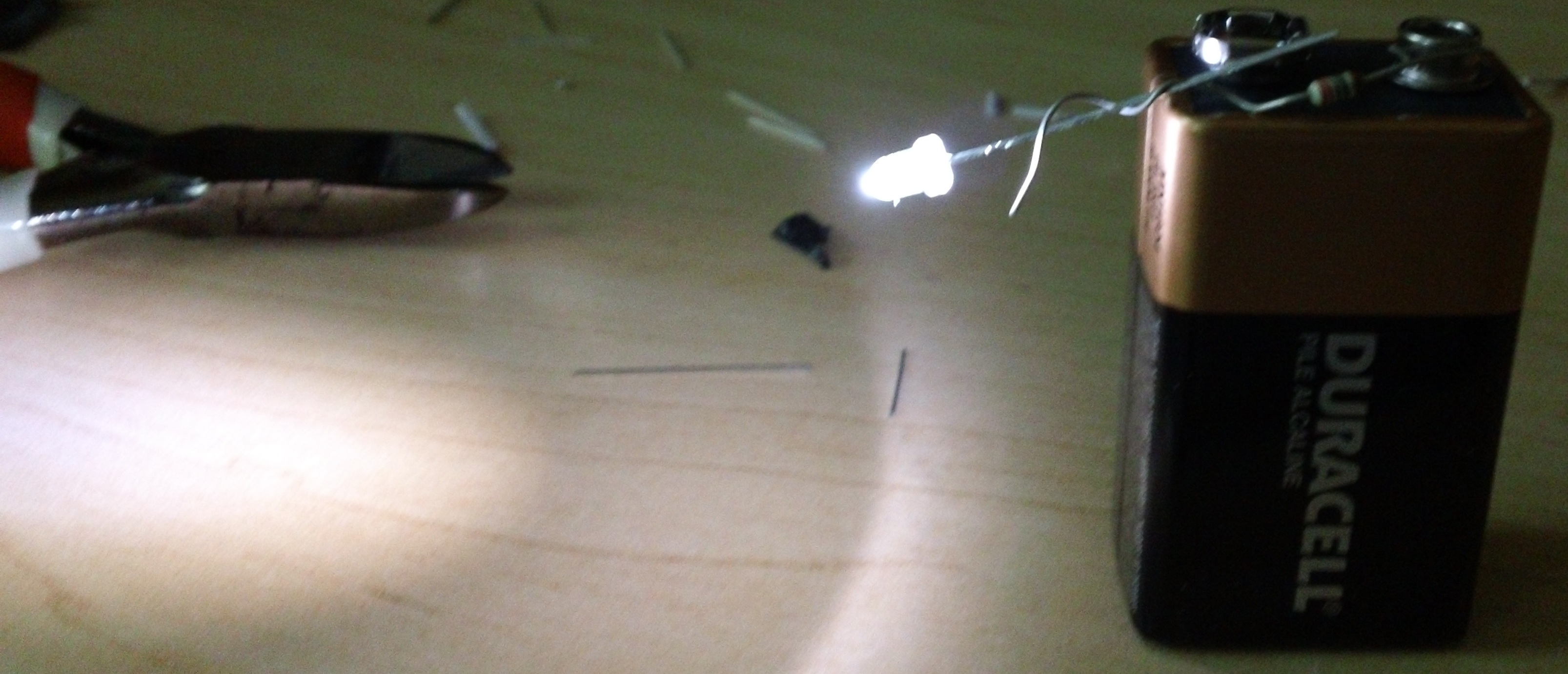
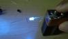
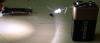
I didn't know there was a wrong voltage to test leds with. The battery is new, the resistor is 220 ohms.
-
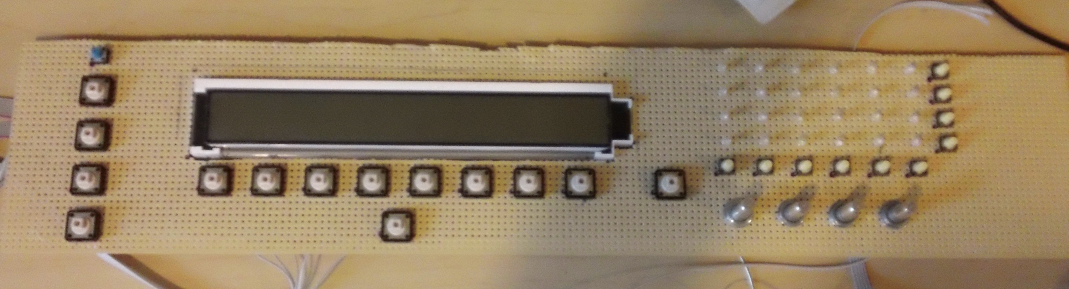
Here are some pics of my FM's control surface. Its not done yet. I'm going with a blue and white color scheme. Since the backlight for my lcd screen is blue and the text is white.


-
I've been thinking about buying a drill press for drilling holes in enclosures. I have a steel or aluminium 2u enclosure, so I was wondering what kind of drill press I should be looking for. I've seen a few benchtop drill presses on craigslist, but I'm not sure what horsepower I should be looking for to drill through this enclosure. Any tips?
-
Anyone know of an easy way to extend an ffc cable? I took apart a lcd screen to build a projector. The lcd screen still seems to work, but I need to extend a ffc cable. Its a 20pin cable. I think the pitch is .5mm.
-
My friend brought me a wallwart that he said he accidentally broke and would like to replace. I've been having trouble finding one that will work. The model number on it is mb132-060045. It is 6v dc at 450ma with a positive tip. I found some that are 6v dc at 500ma, so I was wondering if we could use one of those with a current limiting resistor. Would that work?
-
I have two old electronic casio keyboards that i don't use and was considering building a midi controller out of one of them, but i've been wondering how the keys in a keyboard work. If the keys are velocity sensitive would they be used as analog inputs for a core? If not, then I would assume they are digital inputs correct? Does the velocity sensitivity depend on the actual key or is something fancy thats done in software? I don't know if this project will actually culminate in anything useful, but its something i've been a bit curious about and have had a hard time finding info on.
-
can tx/rx are on pins 35 and 36, which also double as lcd data lines 2 and 3. They are also used for connecting to the opl3 board in the fm. So it probably wouldn't work unless things were moved around. Maybe i'll just go with iic.
-
i was digging around more on ucapps, and after reading about mbnet, i was wondering if i couldn't just use that. I realize that the pic18f452 doesn't have the ecan peripheral like the pic18f4685, but can the fm run on the pic18f4685? Because according to this http://ucapps.de/midibox_network.html mbnet is more efficient, and based on my understanding it shouldn't require additional hardware (iic modules), but may still require a 3rd core. Would this also work?
-
I ordered parts for another core, and 2 iic modules, and having started working on the cs and the case. As far the code goes, I need to learn assembly. I only know c... But to get started, the code on the core with the cs needs to be modified to send stuff to the correct IIC module, as well poll the IIC modules to see if it has received anything back from the cores right? Would it be worthwhile to use the RI# pins of the IIC modules so polling is not needed?
-
i drew a picture just to make sure we're on the same page. This is what your talking about right?
-
So, the CS would be connected to that core and then the other cores are connected to the IICs right? I was looking through the manual, and it seems there is a sysex dump option in the CFG menu. Maybe that could be made to work the way I want. Also the programming required would be in assembly right? I only know c...
-
ok, so i now have parts for 2 fm's, (2 cores, 2 opl3 boards), but only parts for 1 control surface. So, I was wondering how I would go about using the one control surface for both cores. I would probably need to make patches on 1 core and use sysex to send them to the other one right? Would i want an IIC module for that or is there some other way of doing this? Another option i have been considering is making 1 fm without a cs and getting a novation midi controller. I've been looking at the novation remote sl 37. Does anyone have any experience using something like this with a fm?
-
woot woot! My FM finally works! I used a continuity checker and compared the pins on the working core with the nonworking ones and figured out i had the polarities reversed on the jacks. Now, I need to work on the CS.
-
the old core uses the midi jacks that go directly on the pcb though.
-
also, i wasn't talking about the wiring of the pins specifically, if you look closely at the picture on the far right http://avishowtech.com/mbhp/images/MIDIJackPanelL.jpg there is a pin with a copper rivet. that goes to the enclosure of the jack. Am i supposed to connect that to ground?
-
I connected the old core and put the new pic in and it works. So, I guess i'll try connecting the jacks to ground as well. I also tried the led thing on the trouble shooting page, and the led flickers when i turn the power on, but doesn't seem to do anything after that. It will only flicker again when i turn the power off. I also tried the loop back thing in mios studio by connecting the out to the in and that seemed to work as well, so i don't think there is anything wrong with the routing in mios studio. i guess i'll try playing with the wiring of the jacks.
-
i am using the midi jacks smashtv sells. Not the ones that go on the pcb, but these http://avishowtech.com/mbhp/images/MIDIJackPanelL.jpg in that picture on the far right, am i supposed to wire that to ground as well? also, by rear view in this picture http://ucapps.de/howtodebug/mbhp_core_extract_midi_plugs.gif does it mean the rear view of the jack so i am looking at the pins on the jack or do i look at the end the midi cable would plug in to. because if its the former, i may have the polarities reversed.