
julianf
-
Posts
322 -
Joined
-
Last visited
-
Days Won
10
Content Type
Profiles
Forums
Blogs
Gallery
Posts posted by julianf
-
-
I must finish an outstanding job first, and then i will do some matt black...
-
Errrh, doesn't seem to match with the black profiles???
??
-
A quick, not especially good (camera has no more batteries for a second go!) photo of the gloss black -

Now in 'shop' -
http://thebeast.co.uk/?product=midibox-mbseq-v4-desktop-enclosure-panel-set-gloss-black
-
Ive been quiet for a while (summer has been getting in the way!) but all but one mbseq panel order are shipped, and ill have some gloss black (silver writing) panels for the group buy in my 'shop' before the weekend is out.
Next will be matt red (white writing), and then, i guess, ill make some more matt black?
The gloss black / silver writing is the same metal as i used to use on my desktop x0xb0x builds -
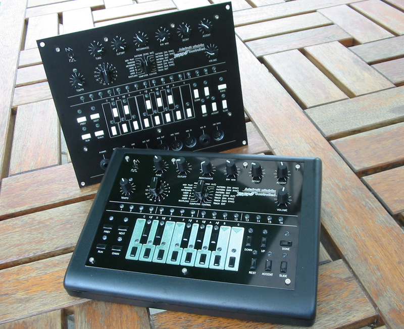
The 5u panel is matt black / white infill, the desktop is gloss black / silver.
Again, sorry for slow replies to those who have mailed me recently.
julian
-
Ive just found another graded mb6582 panel here, and put it up for sale -
http://thebeast.co.uk/?product_cat=otherpanels
Price - GBP 65 (normal price GBP 85) -
re: panels -
for my own personal build, for which i could cut the panels however i wanted, where machine time, or metal cost would be largely irrelevant, i will use the design above, as i think it is a stronger, neater panel than the original design. to re-iterate, i can cut my own panel however i choose, and i will cut it to this design (unless the hardware changes by the time i get around to it!)
-
What are the "real" measurements?
I discussed it in detail here -
134.8mm dimension in the visible y-axis(It is the y that is the hard one on these enclosures)
The x can be copied from the rear part without concern, but, from memory it was about 0.5mm larger than datahseet. (i can confirm this later)
-
hello guys ... are you talking about a 300e box ??? :getlost:
This is the case -
http://www.ucapps.de/midibox_seq/mbseq_case_measures.pdf
Do not 100% trust the datasheet (ever?) when looking at measurements though.
-
And now for some photos -
And for kristal, just to show that the panel really does not come off the case, a shot of it hanging off my claw -
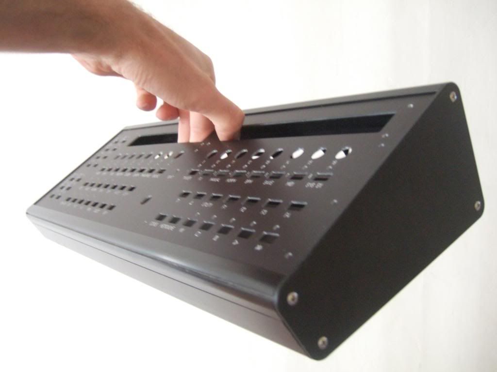
I only have one panel set finished right now (the one in the photos above) and i have it listed in my shop - http://thebeast.co.uk/?post_type=product (again, thank you xtrmnt)
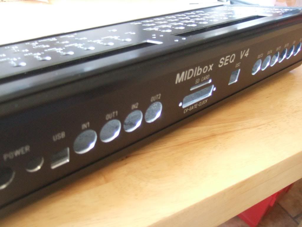
The back panel is not that clear in the photos above, but it matches the screen grab i posted previously. Ie it has the OSC port, the power switch has been changed to a common SCI part, and an additional DIN port added.
Im out all day tomorrow, but i will add three more units on Wednesday. The shop will update as / when any units sell.
-
 1
1
-
-
I don't need a front panel. Thanks Julian! :smile:
: )
(chris helped me with some woocommerce stuff, so i sent him a set of panels for the case previously)
-
In answer to you both - the attachment was simply to look at the hole positions, not how anything was to be cut at all. Its a very old photo of a panel cut years ago. All i was wanting to draw attention to were the two redundant holes.
You have given me the information i was looking for though - thank you! : )
-
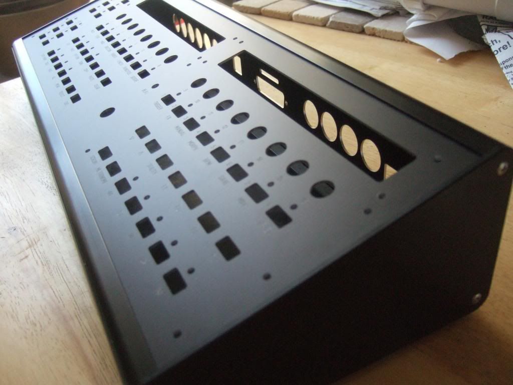
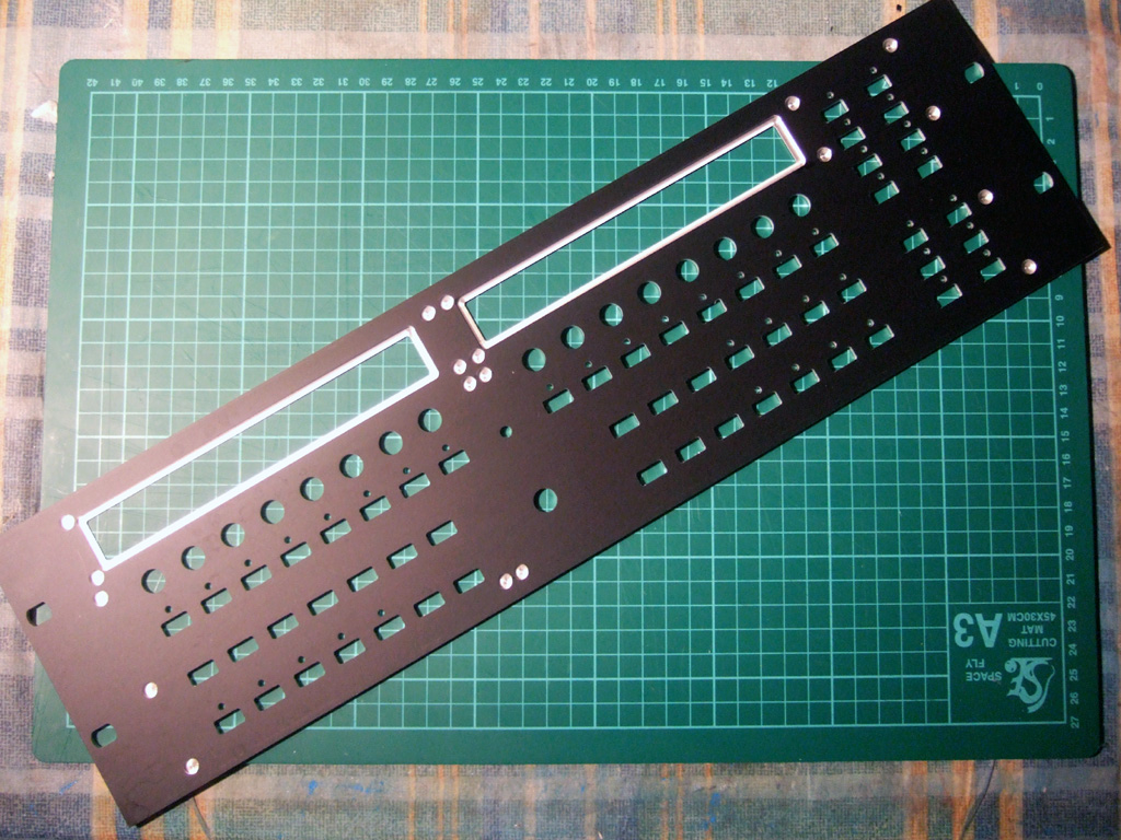
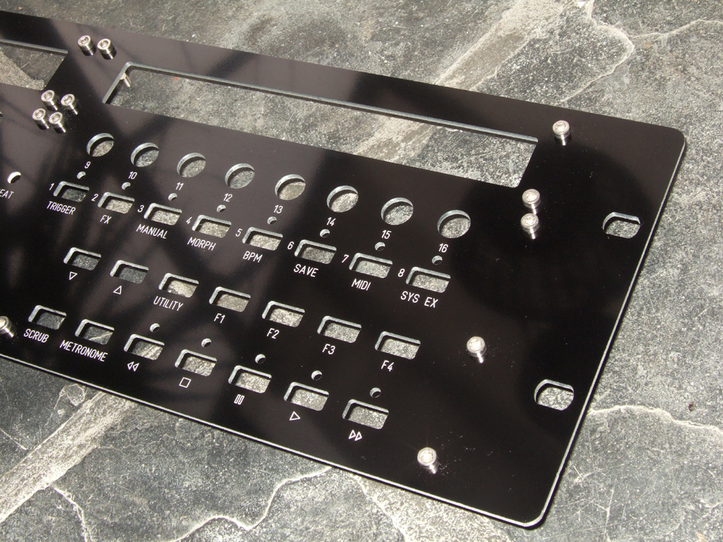
Can i have confirmation on one thing -
The red holes, in this image (click to make it bigger!) -
Should i *not* cut these for the panels?
And to be 100% clear - the photo above is the REAR of the panel, not the side you see.
(ie a mirror image of the top side)
Im sorry if this is obvious, but i just need to be 100% certain before the next stage of cutting! : )
-
Just a quick post -
I have been working on some panels for these cases. I should have a couple of sets complete by tomorrow evening (30th july) with more to follow.
-
Ive just uploaded a few parts to my 'shop' and made some minor reductions on a couple of midibox panels that have been here for some time.
direct link is here -
http://thebeast.co.uk/?post_type=product
Midibox stuff is under 'other panels'
Thank you,
Julian
-
ps.
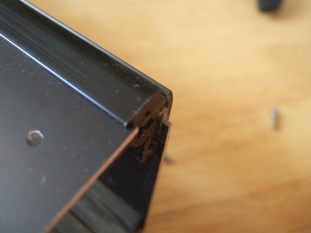
Even without locking into the ends of the case using the parts you are looking for a name of (tabs/protrusions/rails?) the panel should still be held by the top and bottom extrusions, shouldnt it? I will have to look again, but im sure the panels hold on all four edges - two fit with the extrusion, and two with the end plates.
But, again, either way, nothing falls off - really, dont worry! : )
-
What I mean: what happens if your turn the case up side down? E.g. transporting it to a gig etc?
I don't have a better word than slide or guide rail for it, I marked them red for you. I even don't have a word in German for it :smile:
Furthermore, I marked 2 recesses that aren't necessary with SmashTV's PCB.
Yep, the panels are fine. Shake the case as much as you like - nothing will fall off : )
The two holes - they were from earlier builds. The reason ive still cut them was to make the panel backward compatible, but i guess its probably time to stop now.
-
When buying a 17" panel, one wants to make sure it has slides for the closing sidepanels (see pic ) so the panel won't fall off the case. The original Wilba front panel file doesn't have this.
Is this what you were asking about the rear panel? Im still not 100% sure that i understand! : )
I have a case from one of the earlier group-buys - i took measurements from the actual case itself, rather than the datasheets, and cut both the top and the rear panels to fit the case.
Indeed, i cut a test panel, and then made further adjustments of fractions of a millimeter, so that, not only did the panel fit, it fits perfectly! : )
Assuming the cases from this group-buy are of exactly the same dimensions as the ones from the last group buy (im sure they will be - they will be cut from the same code, im sure!) then any panels that i cut for them will, again, fit perfectly.
Again, i am not 100% sure i understand, but, even if i do not understand, i can assure you that there will be no falling off the case! : )
(in short - there is nothing to worry about ; )
-
why not use counter sunk flat head screws. Those will be flush with the panel and you're still doing all the work on the front of the panel
In my personal opinion, i think counter sunk often look much worse. They are ok if you have the screw in your hand, and you gently take out more and more metal, and keep checking as you go, but, for any other job, through panel work, the screw either sits proud, or the hole is a fraction too large, and you get that silver 'halo' around the screw head.
Of course, things should be perfect, and i know there are DIN specs etc., but, in reality, ive seen so many countersunk screws with the 'halo' around them, and, to me, it looks like an error. I think the only perfect ones ive seen are ones done by hand, with the screw present to match when making the hole.
Again, it is only my opinion. For my own works, i generally always go for the stainless steel allen cap bolts. I like the look of them! : )
-
Here are two photos to illustrate the above -
First, a panel with the rear milled for the screen, and also recesses for hex-spacers (wilba originally specified threaded blinds) -
Again, this is the *rear* of the panel.
Next is a photo of a panel with no milling on the rear. The pcb is mounted with bolts from the front of the panel. This is a much stronger, simpler, cheaper way of producing the panel, but it does mean that you see the bolt heads (in this case, A2 stainless allen cap heads) -
For my own, personal, build (where machine time is not really a consideration!) i will use the latter mounting, as i think it is better, but, again, not everyone likes to see the bolt heads.
-
Here is a screen grab of the existing file -
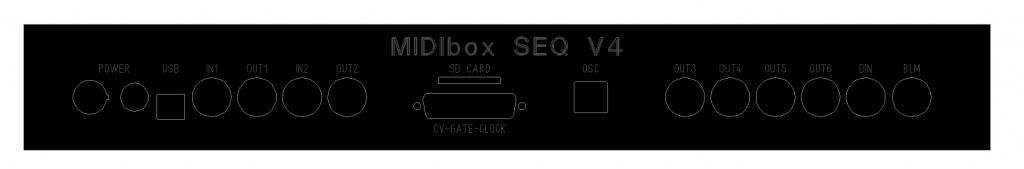
The changes from Wilba's original are limited to -
- Small adjustments in dimensions to fit the Heidenreich a little more accurately
- The addition of the extra DIN port
- The change of the power cut-outs to match more commonly available parts (the round switch is an SCI part, and the jack could be pretty much anything)
I am not familiar with the LPC17 core - if further changes are required, then the files will be edited to accommodate.
-
-
They are available, see
I am sorry - i missed that.
I'm just waiting for 3 additional participants to hop on the bulk, maybe you could help filling in the gap?I would like to keep the case in stock (as i say, people have asked over it in the past) but there is always more to spend money on than keeping slow moving stock.
I would be very happy to make up any and all short-fall on the cases (i will keep them in stock for people at a later date), if it is possible for me to generate the required revenue from machining matching panels. I would be very happy to spend the revenue from any sales (even as 1-off units) on any of your short-fall and keep them in stock for future buyers.
Even if i make no sales, i would still like some cases for stock, as above, however, then i have to redirect money especially to the purchase, which is always more difficult - so i would try and buy either way, but one way is much easier for me than the other.
-
I have just re-read your initial post again -
- Haven't contacted Heidenreich yet, in a week I know more.
I would suggest waiting to hear first about the enclosures, before going too far on other paths. I mailed Heidenreich some time back, asking for a quote on 1-off, and received no reply. This could have been due to any number of reasons, but, as this is the essential part, it may be wise to confirm its availability?
I will post a screen grab of the rear panel i most often cut for people. It is the same as Wilba's but with the power switch changed to an SCI item (due to people finding the original hard to obtain) and the addition of one extra MIDI port (with the same spacing as the other ports).
The rear panel is easy enough to customise, but most people in the past seem to be happy with this configuration. This does, however, not simplify the 3d alignment - as per Altitude's comments above.
-
are you planning on using the extrusion for the left and right sides, or for the front and back?
either would be possible. it would seem more 'natural' to use the extrusion for the front and rear edge, and then make wooden (or metal) ends (for the right and left) but that would mean machining the profile itself for the i/o at the rear.
if you used the extrusion for the right and left, then it would be much simpler to cut the front and rear, and cut the i/o into the rear as per normal. Im just not sure it would look as classy as with the wooden sides.

SEQ4 Heidenreich Case Bulk 2014 / 2015
in Bulk Orders
Posted
Completed unit looks nice!
I looked to see if the whole panel could be offset down a little, but the mount issue is on both rails, so there is no option.
If the screw was glued to the panel, and then a nut glued to the thread of the screw in the right position, then it would fit without grinding the rails, but then you are back to the weakness of glue.
As above it is simple enough to grind a small section of the rail. That section is not really used anyhow (it was to hold the captive 'nuts).
Thank you for the photos. It is always nice to have further confirmation that all is correct.