
Psykhaze
-
Posts
311 -
Joined
-
Last visited
-
Days Won
8
Content Type
Profiles
Forums
Blogs
Gallery
Posts posted by Psykhaze
-
-
Also , Force sensing Sensors from Interlink might worth the look too to plug on AIN : https://www.interlinkelectronics.com/fsr-406. Then a silicon plane on top and you have a rubbered drumpad :)
regards,
Jerome -
Hello,
Nice "hardware" informations : https://www.edrums.info/ - https://www.toontrack.com/forum/e-drum-workshop/design-2z3z-choke-capable-cymbal-by-pfozz/#p46574
Regards,
Jerome -
Please stop flooding and complaining. Take your time to understand ucapps and wiki, read things and instead of triple posting make a consistent post instead.
regards,
Jerome -
Hi Chris,
maybe something like this might help ? : https://fr.aliexpress.com/item/STM32F4discovery-STM32F407VGT6-ARM-Cortex-M4-32bit-MCU-Core-Development-Board/32828318079.html ,
it's still bigger than your purposal that i would have preffered something like https://fr.aliexpress.com/item/Minimum-system-board-STM32F103RBT6-development-board-bottom-with-adapter-plate-Combo/32761293191.html
to stay compatible with existant firmware/MCU used . But maybe still bigger that what you might expect.
Hope it helped anyway :)
regards,
Jerome -
Hi all ,
is it possible to have separated matrixes with the SRIO ? the special design i have in mind for example is having : [DIO-MATRIX]----[DINX*]----[DIO-MATRIX] modules linked together , like if for whatever routing reasons you have to handle encoders in middle of two matrixes of switches/ LEDs to stay modular for example. Any would say that the most easy would be to do [DIO-MATRIX]---[DIO-MATRIX]---[DINX*] to keep the matrix united but i wanted to know if the mentionned design might work?
Also , is having 2 AOUT+ 2 AIN on the SPI port sounds acceptable ? wouldn't be the total data to handle becoming a bit big if you try to mux Analog ins to end with a 16 outs + 128 ins ?
Thanks in advance for your answers,
kind regards,
Jerome -
Ok thanks dudes , i think i will add the 0.1µF cap on encoders , the bunch of extra resistors and "switch cap" seems then not a real use.
-
Hi Folks,
currently working on a Control Surface PCB driven by DIO i was wondering if such debouncing schems might help or if it was an overcome:
Encoder: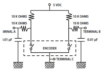
Switch:
regards,
Jerome -
i'd recommand Code::Blocks , Cross-Platform and Easy to interface with any compilers
-
@ksir has redrawn the SeqV4 Wilba CS PCB over KiCAD for his personal use and everything was like working . Process documented over http://ksir-diy.blogspot.fr/2016/07/seq-v4.html
Maybe you could kindly ask him to run a batch ?
Regards,
Jerome -
A look over the SVN always help :
http://svnmios.midibox.org/filedetails.php?repname=svn.mios32&path=%2Ftrunk%2Fapps%2Fcontrollers%2Fmidibox_ng_v1%2Fsrc%2Fscs_config.c
After a detailed read you should be able to get rid of some problems ;)
Greets,
Jerome -
Pretty =)
-
That's a way it could be done , i was sure i have seen the piece of code for this somewhere on the svn but after minutes struggling i can't manage to find it again. If i remember well he used some 93XX from NXP.
The why about the MCP23017 / MCP23S17 is that it is having configurable GPIO ( 16 pins acting like or DIN or DOUT depending on the configuration,with possible mixed design) , twice the number of a serial register > for example 2 of these to scan a 16x16 BLM buttons> Lowered number of components. And the argument of mixed I/Os might allow customs I/Os mixed designs based upon only one kind of IC.Once again,it's just a thought. It has been used widely in the arduino world.
My other point is about RGB LEDs PWM and cost/number of IC used. Can be done with many I2C/SPI chips, like Ander did with the station (Do anybody remember the chip he used or where the code is?) , or serially with WS2812-alike like you used on your sparkfun pads @latigid on . Problem with ws2812 despite the great design is the price (and sometimes size, being most of the time 5mm-wide on sizes, even on SMT).
When i purpose about MAX6960 especially , it was because it attracted me with it first purpose , being a bicolor(R/G+Y) 8x8 matrix driver , that could be extended to RGB (BLM) designs and easily chainable. (remember old MBHP Bicolor BLMs? ^^)
Some DIP (even SMD) RGB or bicolor LEDs are really cheap to get x1000 units (and size decreased compared to WS2812) and the column-row driver design attracted me because of the all in one design that could manage 16x8=128 monocolor leds at once , with PWM or 8x8 Bicolor Matrix. Just another though,that is not an -absolute- solution purposal but just one way that could be used to decrease components number, with qualities and defaults too =)
-
These scans are pretty cool , it should end in the wiki too !!
As some members mentionned , off-site doc tend unfortunately to disappear along time. -
Right, I forgot that some 74HC541 Line Drivers are on the core board already ^^
I am wondering what's the real problem with SPI?
i know that an I2C implementation would be somewhat easier moreover regarding available ports (J4A / J4B > I2C, only J19 offering SPI and should be reserved for analog) and that's almost like SRIO works.
To me Shift register are quite Ok for everything they are bound to , only the LED paradigm might need some recent thoughts because the current thing or RGB PWM.
About "pure" I/O expanders i also noticed MCP23017 / MCP23S17 from microchip (configurable 16 I/O) >MCP23017/MCP23S17 Datasheet<
Wide packaging options, Driver Source code widely available or easily portable (example https://github.com/dreamcat4/Mcp23s17)
SPI chips are for sure not as "long-term" as Shift registers but might offer recent features and practical sides (i especially think about Huge RGB config where using shift register might be harder than using an SPI thing because of big number of lines).Cross & Retro Compatibility are important for sure but for some config i guess that betting on some of these SPI things might make the design a lot easier by lowering BOMs , improving routing and component number,decreasing global price and offering Increased Control. (think about a 16x8 matrix in RGB for example) To me the only problem about SPI chips is availability in time but it might be a middle term alternative.
Nevertheless, Using PNP / MOSFETs / LED buck boost sound a good practice to me , but regarding the size of MIDIbox configurations (Excepted BLMs) it might be more a painful and somewhat not really useful thing. SR can handle their hybrid role managing Current and Control on small to medium Config , keeping the BOMs small. Look what sauraen did on the Genesis CS, using only Shift registers (+few row drivers)
But (Big/Non-Serial RGB) BLMs might require something better to handle it than a ton of shift registers. And in this case , using "power drivers" and SPI/I2C LED drivers might sound really more making sense.
Edit : some nice I2C LED drivers from NXP , known as offering better long time support than maxim :
http://www.nxp.com/products/interfaces/ic-bus-portfolio/ic-led-display-control:MC_48878
Link to LED driver SPI chips from Maxim mentionned in the Picture Conversation:
https://www.maximintegrated.com/en/products/power/display-power-control/MAX6960.html
https://www.maximintegrated.com/en/products/interface/controllers-expanders/MAX6966.html
Also notice that regarding respective bus speeds , an I2C emulation -might- be coded over a SPI I/O chip like MCP23S17
Principle : http://www.microsemi.com/document-portal/doc_view/130041-ac324-spi-to-i2c-interface-app-note
-
Smithy inna (techno)minimal style =)
-
-
Impressionnant , j'avais deja vu quelques démos mais la ça bat des records. Le mode séquenceur en faders motorisés est tout bonnement excellent!
Chapeau bas , la reactivité des faders et les fonctionnalités implémentées sont vraiment chouettes!
Gros boulot ! Mes félicitations en tous cas.
Jerome -
POW !!! - These arps :o
-
Chiptune <3
-
Always a pleasure to see #dawless music =) Bewarea bout not going off rythm too , after listening again there are (little parts) where it's sometimes tricky (but sh*t i like this battery pad ^^)
However nice work ,hope to hear more !
-
Hi folks,
Seeing that the OLED subject is kinda hot these times, i was wondering if anybody has been playin with these ones :
http://www.buydisplay.com/default/serial-spi-color-0-95-inch-oled-display-module-96x64-pixels-ssd1331
SSD derivative , with some code tweaking could be ported to MIDIbox for those interested, but color management might bring memory overloads?.
If nobody feels like coding just put it in TK's TODO :D
Bests
Jerome -
Polivoks VCF gives SID nice ruffness =) Aerial and sweet style SIDhead-feeded , hawkeye's mark. like it !
Greets,
Jerome -
Hey pretty one =)
cheers
Jerome -
Sorry for laming . I'd just wanna say something about that great nice work

What are the ribbon cable connectors called
in MIDIbox SID
Posted · Edited by Psykhaze
More generally these are called IDC or IPC connectors : https://en.wikipedia.org/wiki/Insulation-displacement_connector .Depending on the "Pitch" , aka pin spacing , you will have different connectors (male/socket/Pinheader +female IDC on wire) . Traditional pin headers used in previous MBHP design have a pitch of 2.54mm/1mm imperial, wich is also the pitch of traditional DIP (through-hole) components. Most of MBHP pinheaders connectors are 2x05 so you can run a search with something like "2x05 IPC connector 2.54" or "2x05 ipc socket 2.54"
Some common brands for connectors are Harwin,Samtec,Molex and Amphenol (at least i have some good experience with their products) But a search on Aliexpress/Ebay/Tayda might give you cheaper results
Regards,
Jerome