
vcfool
-
Posts
55 -
Joined
-
Last visited
Content Type
Profiles
Forums
Blogs
Gallery
Everything posted by vcfool
-
Hi, I am still using the old core STM32 and Wilba's frontpanel and I have a request that would make my workflow faster and easier. Would it be possible to have the Datawheel and Up/Down buttons to do different things in Step Edit mode? So when holding the Edit button I would like an extra parameter for the Up/Down buttons just like the one for the Datawheel. Then we could for example use the Up/Down buttons for selecting the Parameter Layer and the Datawheel for value, step or any other combination. Thank you very much again.
-
This exact same thing happened to me with my STM32 SEQ v4 (first version STM32, not STM32F4). I actually solved it this way: I decided to upload the previous versions to check when the bug was introduced, but I ended uploading backwards to such old versions on which I was sure this didn't happen at the time of release. I think I got back to something like "midibox_seq_v4_074" and the bug was still there! So I gave up. Uploading such previous versions and the corresponding old "hwcfg" file made my configuration parameters not valid. So when uploading back to "midibox_seq_v4_094b" I had to manually reset all my MIDI Router parameters and other settings in the "Options" page which got deleted. After doing this, the BPM LED started blinking correctly on the beat again. So I am guessing that something was messed up in the MBSEQ_GC.V4 file or somewhere else. Hope I am making myself clear and that this will help.
-
Yep, now it works. I just made a quick test and the IIC Outs work nice with v4.075pre2. Thanks again.
-
Hi, I just tried the above v4.075pre1: The Seq seems to find the IIC outs. No more "*" appears next to them and I can see the the IIC out activity on the MIDI Monitor page. But still, there is no actual data coming out of the IIC Ports physical outputs. Thanks again for the ultra-fast support!
-
Thank you so much! I knew I did something stupid that I shouldn't have done. MIDI uploading worked fine. I plugged my GM5 and upgraded to v4.074 successfully again. Nice. :smile: And now the 4x IIC_Outs are no longer recognised by the Core. :sad:
-
I think I messed up something in my SeqV4 (STM32): :sad: A few days ago I succesfully uploaded from 4.065 to 4.074. I updated both the bootloader and the application and everything seemed fine. But just tonight I noticed that none of the IIC Out ports were no longer seen by the Core. The "*" symbol appeared next to all 4 of them. I thought that before opening the machine to look for a hardware fault, I would check that it wasn't caused by the newly uploaded version 4.074 of the application. So I uploaded 4.065 again and the IIC ports came back to life. So now I have my IIC ports working fine again, but MIOS Studio is reporting an error every time I try to upload the application or the bootloader. No matter which version I try to upload it all seems to start fine, the Seq LCD's show Bootloader mode for some seconds, but then it just reboots and MIOS Studio shows the message: "Upload aborted due to error #14: Invalid SysEx command" Now I see that I probably did something silly and maybe Bootloader 1.012 + v4.065 is not a good combination. This all happened using MIOS 2.4.4 on OS X 10.8.3 So I'd really like to know if there is a way to fix this and get the USB uploads working again or will I get stuck on 4.065 forever? Thank you all very much! And someone with 4.074 and IIC Out ports installed should check if they work. :smile:
-
Hi, I upgraded from v041 to v048. Something is wrong with my Drum tracks when played from an external MIDI keyboard: The Drum sounds appear repeated several times over the whole keyboard and some MIDI notes don't trigger the right sounds. Using the Live Play mode works fine. Sequenced tracks also work nice. Just direct playing/recording from the external keyboard seems to be affected. I just tried version 42 which is the last one I downloaded (but never really tried) and the problem is also there. Maybe I am doing something wrong. I went back to v041 and all is fine again. Thanks again!
-
Great! Thanks! :)
-
Just upgraded from Beta35 to 38. I am using Wilba's CS and found that BUTTON_PAR_LAYER_A is not working for me. I can confirm that it is not a hardware problem: MIOS Studio detects that the button has been pressed/depressed but says that it's not mapped. I went back to Beta35 and the button works fine again. Thanks! :)
-
Sorry if I am misunderstanding your idea, but are you aware of the "Scroll" function? I'm not sure that I do understand the differences between the already implemented "Scroll" and your "Cycle" idea. :)
-
Nice, thanks again! Been quick trying right now and I think there is a problem with the normal Step View Edit Mode: The lower line of the LCDs is always displaying the Notes for Steps 1-16, no matter which steps are selected holding the "Step View" button. The upper line of the LCDs and the GP LEDs do show the actual values and edit seems to work, but the lower lines always show the Notes and Lengths of Steps 1-16. Also Length Parameter Layer is showing the bars on non-gated steps: Clear the Track and all the steps will show a Length bar indicator. This didn't happen on previous versions. Maybe I am just doing something wrong... :)
-
I have been thinking that such a feature would be useful too. Maybe just adding an "Advance Step Parameter" like the one found on most Tracker style sequencers: Set it to "0" not to advance any step when inserting a note, set it to "4" and advance in quarter notes intervals... etc...
-
This is already implemented: -Go to MIDI -> Transposer and Arp. -Select 1 Bus and choose the right Port/Chn/Range. -On "Mode" select "Play". Not sure I completely understand you... There is a 3rd MIDI In/Out on the Core for the BLM now. But you can use it as a normal MIDI port. I have 2 keyboards and 1 sequencer connected to the MIDI INs of the MB-SEQ v4. Using all 3 Core inputs without any problem. Hope this helps.
-
Nice! My 2 cents: Would the extra resistors for the LEDs fit on the PCB? Maybe somebody wants to use them, so they may be a good addition. At least adding only a soldering pad next to pins 6 and 10 of each PIC, without resistors, so one can add the resistors and LEDs if needed. Just a thought... Then, looking at your PCB vs the schematics, I see you have connected pin 6 of the PICs to J2 (SV6 on your PCB). As far as I see, Pin 6 should be the "Power ON" LED, and pin 7 is the one that should go to J2. Am I wrong? :)
-
AOUT NG : only half expected voltage in bipolar
vcfool replied to julienvoirin's topic in Testing/Troubleshooting
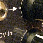
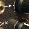
Well, so I have the same situation here. I have an AOUT_NG inside a MB-SEQ v4. I have been using Unipolar mode without any problems since I finished it some months ago. I have been following this topic and just now I tried the Bipolar mode. So far I have only tried CV1: On the Mixer Map I assigned a CC to the AOUT CV1 output and calibrated P9 to have 0V at a CC value of 064. And I have the same problem: the output range is only -2,7V to +2,6V. -
I get the behavior you mention when I got the "Synch to Measure" enabled under the track's "Divider" page. Maybe your drum track has this enabled and your non-drum tacks have not. Just a thought because I still don't really fully understand the Synch to Measure feature. :)
-
MBHP_ETH, MBHP_SDCARD, SSM2044, SSM2164 PCB Bulk Order
vcfool replied to seppoman's topic in Bulk Orders
Got mine today. Thank you very much! -
Nice, thank you! I've been trying this tonight for a while. Can't wait for a "real" one. :)
-
Great. Nice project! I have been using 4066 to trigger some of my bend devices. The 4066 controlled from analogue sources: Gates and Triggers from analogue synths or MIDI-CV converters. I'd be interested on building and trying one of this. Are you using a custom MIOS application to control the VSS-200?
-
Ah ok, now I get it. I think I know what Echopraxia means because I have noticed it too. I will try to explain: When you enter to the Trigger Assign page, (sometimes) the page will not be displayed correctly. You get the Trigger Layer Select page instead. If you then press (and release) Trigger Layer C button the Trigger Assign page will show. Pressing the Trigger Layer C button on a Drum track will do nothing. You have to switch to a Note track first. But once the button has been pressed, you can go back to the Drum track and it will also show the Trigger Assign page correctly. Hope I made myself clear. Thanks again.
-
This is great. Thank you very much! Is there any special reason for the CC events on Note tracks to be sent on every Step?
-
To start with the classics, I attached 2 .mid files created with ReCycle. The forum didn't allow me to upload .mid files so I added them both to a .zip. MIDIbreaks.zip AmenBrother.mid -> 4 Bars - 61 Slices (C1/C6) - 138.000 BPM ShackUp.mid -----> 4 Bars - 45 Slices (C1/G#4) - 113.325 BPM BPM is only relevant when playing the same sliced sample. I can attach the .rcy files if needed. I guess at this point these breaks are kind of public domain ;) Many thanks again.
-
Hi, I was going to throw exactly the same 2 cents about this. :) Importing MIDI files from ReCycle would be great. I have been doing it manually for now. These are simple one-track monophonic files but require quite precise timing (no quantize). I guess this would involve somehow the use of one DELAY Parameter Layer and correct Divider/Length values for the SEQ target Track. I am not in need of importing MIDI files containing several polyphonic tracks. Whenever I had to import MIDI files from one machine to another (Cubase created files to an MPC for example) it always involved quite a work on my part. And that was fine for me. Because I really needed to adapt, cut, slice... the "linear" Cubase song, to several tracks/parts to play live. So logically this is a work that can not be done automatically by a program. So, for me, it would be more than enough to import one-track MIDI files to a single SEQ V4 track, one at a time. Thanks again. We were discussing about the Record function on the chat some days ago, and got to this conclusion: The Recording Port is the one selected on Trans/Arpg but then the Channel assigned to the Trans/Arpg is not getting recorded. Use the same Port but a different Channel. Hope this helps. :)
-
I have tested these extra buttons. The table in my previous post seems to be correct. Now to find the LED. :) Thanks! EDIT: I found the extra J3 LED --> SR 17 Pin 0. If I am not wrong, I also noticed that there are another 3 free matrix positions: SR 19 Pin 0, SR 20 Pin 3, SR 21 Pin 0. These do not have jumpers on the board and I have not checked how hard it will be to add these LEDs.
-
A quick question about the PCB: Is there a schematic/diagram showing how the LED/Buttons SR matrix is connected? I am trying to find out the SR/Pins of the extra LED and Buttons to assign them on the MBSEQ_HW.V4 file. If I understood correctly: -There's one unused LED on J3. What SR/Pin is it using? -The extra buttons on U6, out of the matrix: I see that the Datawheel button goes to U6 pin 12 and the GP encoder buttons to pin 11. I also noticed that the other side of U6, pins 3-6, are free. That would make 6 extra assignable buttons. Can somebody please confirm that I got this correct: U6 Pin 11 is SR 6 Pin 0 on the HW file (GP encoder Buttons) U6 Pin 12 is SR 6 Pin 1 on the HW file (Datawheel Button) U6 Pin 3 is SR 6 Pin 4 on the HW file U6 Pin 4 is SR 6 Pin 5 on the HW file U6 Pin 5 is SR 6 Pin 6 on the HW file U6 Pin 6 is SR 6 Pin 7 on the HW file Many thanks again.