

Shuriken
-
Posts
973 -
Joined
-
Last visited
-
Days Won
11
Content Type
Profiles
Forums
Blogs
Gallery
Posts posted by Shuriken
-
-
Because
a. I need +5, +9, +12 and -12 volt rails so I would need 4 wallwarts with your solution.
b. Wallwarts are uncool, more than 1 wallwart is seriously uncool (IMHO). 4 wallwarts is not only insanely uncool, but also extremely impractical.
c. What's the fun in using wallwarts? I like it better if something is custom and/or expirimental. Besides, if it turns out switching PSUs aren't evil anymore per sé, lots more Midiboxers could benefit from that info, so I plan on ordering one in the very near future. Might even finish my 6582 project that way.
And you're exactly right to do so. (IMHO again)
Cheers, Alex.
Display sells the t40 one for something like 34 euro. Couldn't find a local supplier for the t30.
-
A couple of weekends have passed. But only today i had a chance to look into it.
Currently figuring out how to hook this thing up. Firstly trying to do 8bit parallel.
The tft board connector looks like this:

The datasheet says these pins need to be connected for 8bit operation:
- nCS (Chip Select Signal)
- RS (Register Select Signal)
- nWR (Write Strobe Signal)
- nRD (Read Data)
- DB[17:9]
The unused DB[8:0] pins must be tied to either Vcc or AGND.
The driver also mentions a nRstPin and a Lcd_LightPin. So i am assuming nRESET and LE EN need to be hookup as well.
Update:- nCS should be connected to DGND if not used.(Low: the ILI9320 is selected and accessible)
- RS can be tied to RS (duh :tongue:)
- nWR to R/W?
- nRD dont use?
- nRESET i assume should be either high or left floating.
- EN should probably be high, so the backlight will be on (always).
-
Silly me, i thought that unregulated implied an AC adapter.
-
If it has a polarity switch i think it's safe to say its regulated.
-
So many questions and so little answers :ike:
My first and probably last question for you is.....WHY?
You say less sensitive to falling. I don't see how 5 stacked PCB of 400x100mm can be less sensitive then 3 tiny IC.
More silly questions, soak the whole thing in water.....You must have been high when you wrote this topic :pinch:
-
Please have a look at the 78xx datasheet at page 24 figure 13.
As you can see there, the application of the transistor is not current limiting. If the current surpasses 1A the transistor will take over. This will increase the current output to a max of 3 to 5A depending on the transistor used. As i said the design is not short circuit protected. So i should adapt it to resemble figure 15. at page 24 of datasheet.
My intention is to use 2 transformers. 1 for 5V and 1 for 9/12V line. The 5volt line is most sensitive. Hence the more intricate SCR design. I intend to include a simpler (less sensitive) zener diode based scr design on the 9V/12V line.
-
This is a good idea, and is very similar to my design. But current limiting / crowbar and fuse is even more important with pass transistor.
I have looked at tip31c as the limit transistor. Its 10A. Havent done the math yet, so ill have to do some calcus to see what the actual needs are.
This is what i have come up with so far:

This design should be sufficient for 5A on 5V+ line.
The TIP2955 is 15A. And the packaging is a bit bigger then the TIP31. I haven't really specced the thyristor yet, just picked one from Eagle lib.
Edit: Meh, i need to add a short circuit protection as well.
-
Hi
As it turned out i had too little time to work on the schem this saturday, so i will do some work tonight and monday evening. I recon i will have a schem ready then for you to see.
I have thought of a couple of new things to add, ie led indicators for normal op and protection.
Ill see if theres a simple way to do it. Afterwards i would need some serious evaluation of the schem from people who knows this stuff, so if anyone feel like they can verify the design and suggest changes, speak up.
Ok, well i am working on my schem atm. Now wondering if instead of just using a 78S05 it would be a good idea to combine it with a transistor something like a tip2955. That way it would have a little more room to breath. And better power dispensation. Also struggling to add the MC3423 to my eagle library. :pinch:
-
I am curious what you have come up with. So looking forward to seeing your schem.
-
I think he means this one:
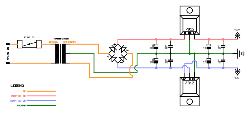
If you adapt this to 2 separate windings then you need to add the diodes again.
edit by nILS: Added a link to the picture's source ;) This design is from the wiki, where you can find some explanation as well. Sadly I ran outta time to brush up the other designs as well. It's back on my ToDo list now.
-
Someone correct me if i am wrong. But incase of a latchup. The parasitic structure (eq to thyristor) can change the polarity. So the GND is changed to a -DC and the +DC is changed to GND.
For the other diode have a look at this datasheet and scroll to page 11.
-
Gotcha. Just haven't seen that design before. Functionally, I'm not exactly sure what happens :) If the regulator fails and outputs 10V, how does the diode on the regulator help exactly? The crowbar circuits I have looked at online (and that have been discussed a bit on this thread) are based upon a voltage max that triggers the crowbar - how does this design differ (since I don't see a trigger)?
As i said, i have to look into a crowbar design. So that's not included into the current schematic. So there is no OVP or OVC protection atm. Just protection for the regulator and for latchup.
-
The diodes around the regulators are there for protection of the regulator incase of input short. The diodes on the output are (old skool) there for the protection of the phenomenom called latchup. As the sid chips are old style CMOS chips they are vunerable to this.
This design is much like Roland's design for the Juno 60. Which holds a lot of 4000 series cmos chips.
When the C64 PSU fails the 5V regulator will put out something like 10V. Since you have 30 euro chips behind it, a 1 euro circuit can make the difference. So i figure you spend a few bucks to safe you from spending a lot of bucks makes sense.
The crowbar circuit is there for when the regulator fails. If i look at the datasheet of the mc3423 it can also help with current limiting.
-
I am also still looking to build a psu. I made a preliminary design:

The pic is kinda dated. As i wont be using a 78S09 but a 7809. Have to look into a crowbar design as well. It seems the zener option doesn't work so well as it might get trigger by a little peak at startup. The SCR option is better. It seems there are a couple of IC options out there. Someone pointed me towards the Motorola MC3423. However this seems to be no longer made. However i just noticed reichelt has it on stock still.
-
Yes I already reached the same conclusion :( There are other boards available that allow the LCD to use SPI but it looks like for some reason the manufacturer left that off, probably because the SPI for the SD card is also shared with the Touchscreen controller......
It doesn't even look like the other configuration pins are available anywhere on the board to force SPI mode.
The other problem is that because of the shortage of I/O on the CORE32, J15 goes via the 74HC595 so reading registers/memory 'from' the LCD is also out of the question which does limit certain things, for example I was hoping to be able to use the LCD controllers buffer memory to save having a screen buffer on the STM32. The downside with this is that anything above 2-3 bit colour is pretty much out of the question.
I haven't quite got the display connected yet (hopefully this weekend) !
Cheers
Phil
Ah, i didn't think of that. I was indeed hoping to use the buffer on the controller. I haven't hooked it up either. Might do on the weekend though.
-
It seems SPI is out of the question. As first of all jumper wise i can only choose 8 or 16 bit. And besides it looks like the sdcard uses the spi interface already.
-
Shipping to either nILS or me would be pretty much the same, as we are both based in Europe. Might be a good idea to wait a bit and see if there are any US based takers.
-
I wouldn't mind helping you out. But it wouldn't be that effective if i live on the other side of the globe. So what nILS said :ahappy:
-
LCD's have arrived today, bit busy so I won't be able to do anything tonight with them. They have an SDCard slot on the back which is quite interesting.....
Cheers
Phil
I received mine as well. I knew about the sd-card. I wonder which way to hook it up is fastest: 8-bit,16-bit or SPI. Well, guess it's trail and error.
-
When it's time. There'll be an announcement on the forum, no worries, you won't miss it.
Can't wait....i am sure it will be a worthy replacement for my half finished MBFM.
-
i've collected 15 SIDs from C64/128 already, however i was wondering to see more and more people selling 6581R4AR on ebay ... so i thought there must be something on stock somewhere around ...
It's probably more like the 8580 was in high demand. And supplies are pretty much running dry. So people turn to the 6581 now.
-
As for the 5V regulator I'd suggest a 7805K in TO-3.
That's still only 1A. The 78S05 can do 2A.
You shouldn't need to regulate the 9 volt output. On the original C64 power supply, 9VAC is provided directly from the transformer.
I have also been pondering building a power supply, starting with a hammond trafo with dual 9V windings. One winding would go directly to the 9V input, the other would be regulated to 5VDC using a standard linear circuit built around a 78S05.
FWIW I used to have 3 working C64 power supplies, and now I have one. Two of them popped while powering up my MB-6582 (with 8x 6582). So a new, beefier, serviceable power supply seems like just the ticket.
I don't know whether to simply build a C64 power supply, or go a step further and put in a housing alongside Seppo's modules (AOUT_NG, SSM2044, VCA), and maybe an audio mixer, plus the required power for all that. The whole thing could connect to the MB-6582 via the DB25 expansion port, which would really tidy things up!
That would be the case if i had a 7809 inside the MB6582. I figured why put an additional heatsource inside the box?
-
As i am still in the process of making my own. I am curious to know what kind of Power Regulators you are planning to use?
I was thinking of using 78S05 and 7809.
-
And i am sure you are wrong on the SIDs as well. If you check the Sammich build guide or http://www.ucapps.de/mbhp_sid.html the SIDS use both 9V and 5V or 12V and 5V.
I am desinging my own psu aswell. Since people have problems with the C64 PSU i figured 1A on the 9V and 2A on the 5V would be on the safe side.
Ersatz Yamaha DX7mk2 interface
in MIDIbox HUIs
Posted
I don't see why not. You just need to lookup the midi implementation chart. A midibox 64 would do the trick.